2017 MERCEDES-BENZ GLE43AMG SUV ECU
[x] Cancel search: ECUPage 331 of 366
Important safety notes
GWARNING
Eac htire, includin gth espar e(if provided),
should be checke dat least once amonth
when cold and inflated to th epressur erec -
ommended by th evehicl emanufacturer on
th eTir eand Loading Information placard on
th edriver' sdoor B-pillar or th etire pressur e
label on th einside of th efuel filler flap .If your
vehicl ehas tires of adifferen tsiz ethan th e
siz eindicated on th eTir eand Loading Infor -
mation placard or th etire pressur elabel, you
should determine th eproper tire pressur efor
those tires .
As an added safet yfeature, your vehicl ehas
been equipped wit h atire pressur emonitoring
system (TPMS) that illuminate s alow tire pres-
sur etelltale when on eor mor eof your tires
are significantly underinflated. Accordingly,
when th elow tire pressur etelltale illuminates,
you should stop and chec kyour tires as soo n
as possible ,and inflat ethem to th eproper
pressure. Drivin gon asignificantly underin-
flated tire causes th etire to overheat and can
lead to tire failure. Underinflation also
reduce sfuel efficiency and tire tread life ,and
may affec tth evehicle's handlin gand stop-
pin gability.
Pleas enote that th eTPM Sis no t asubstitut e
for proper tire maintenance ,a
nd it is th edriv -
er' sresponsibilit yto maintai ncorrec ttire
pressure, eve nif underinflation has no t
reached th elevel to trigge rillumination of th e
TPM Slow tire pressur etelltale.
US Aonly:
Your vehicl ehas also been equipped wit h a
TPM Smalfunction indicator to indicat eif th e
system is no toperating properly. The TPM S
malfunction indicator is combined wit hth e
low tire pressur etelltale. When th esystem
detects amalfunction ,th ewarning lamp will
flas hfor approximately aminute and then
remain continuously illuminated. This
sequenc ewill be repeated every time th evehi-
cle is started as lon gas th emalfunction
exists.
When th emalfunction indicator is illuminated,
th esystem may no tbe able to detec tor signal
low tire pressur eas intended. TPM Smalfunc -
tion smay occur for avariet yof reasons,
includin gth emounting of incompatible
replacemen tor alternate tires or wheels on
th evehicl ethat preven tth eTPM Sfrom func-
tioning properly. Always chec kth eTPM Smal-
function telltale after replacing on eor mor e
tires or wheels on your vehicl eto ensur ethat
th ereplacemen tor alternate tires and wheels
allow th eTPM Sto continue to function prop-
erly.
It is th edriver' sresponsibilit yto set th etire
pressur eto that recommended for cold tires
whic his suitable for th eoperating situation
(
Ypage 324). Not ethat th ecorrec ttire pressur e
for th ecurren toperating situation must first be
taught-in to th etire pressur emonitor. If there is
a substantial loss of pressure, th ewarning
threshold for th ewarning message is aligned to
th ereferenc evalue staught-in .Restart th etire
pressur emonitor after adjusting th epressur eof
th ecold tires (
Ypage 330). The curren tpres-
sures are saved as ne wreferenc evalues. As a
result , awarning message will appear if th etire
pressur e
d
rops significantly.
The tire pressur emonitor does no twarn you of
an incorrectl yset tire pressure. Observ eth e
note son th erecommended tire pressur e
(
Ypage 324).
The tire pressur emonitor is no table to warn you
of asudde nloss of pressure, e.g. if th etire is
penetrated by aforeign object. In th eevent of a
sudde nloss of pressure, brin gth evehicl eto a
halt by braking carefully. Avoid abrup tsteering
movements.
The tire pressur emonitor has ayellow warning
lamp in th einstrumen tcluste rfor indicating
pressur eloss or amalfunction .Whether th e
warning lamp flashes or lights up indicates
whether atire pressur eis to olow or th etire
pressur emonitor is malfunctioning :
Rif thewarning lamp is lit continuously, th etire
pressur eon on eor mor etires is significantly
to olow. The tire pressur emonitor is no tmal-
functioning .
Rif thewarning lamp flashes for aroun d a
minute and then remain slit constantly, th e
tire pressur emonitor is malfunctioning .
Tire pressure329
Wheels and tires
Z
Page 333 of 366
You can find more tire pressure values for
various operating conditions in the tire pres-
sure table inside the fuel filler flap
(
Ypage 324).
XMake sure that the tire pressure is correct on
all four wheels.
XMake sure that the SmartKey is in position2
in the ignition lock.
XPress the =or; button on the steering
wheel to select the Serv.menu.
XPress the9or: button to select
Tire Pressure.
XPress the abutton.
The multifunction display shows the current
tire pressure for the individual tires or the
Tire pressure will be displayed
after driving a few minutesmessage.
XPress the :button.
The UseCurrentPressuresasNewRef‐erenceValuesmessage appears in the mul-
tifunction display.
If you wish to confirm the restart:
XPress the abutton.
The TirePress.MonitorRestartedmes-
sage appears in the multifunction display.
After driving for a few minutes, the system
checks whether the current tire pressures are
within the specified range. The new tire pres-
sures are then accepted as reference values
and monitored.
If you wish to cancel the restart:
XPress the %button.
The tire pressure values stored at the last
restart will continue to be monitored.
Radio type approval for the tire pres-
sure monitor
CountryRadio type approval number
USAFCC ID: MRXMW2433A
FCC ID: MRXGG4
FCC ID: MRXMC34MA4
CanadaIC: 2546A-MW2433A
IC: 2546A-GG4
IC: 2546A-MC34MA4
Loading the vehicle
Instruction labels for tires and loads
GWARNING
Overloaded tires can overheat, causing a
blowout. Overloaded tires can also impair the steering and driving characteristics and lead
to brake failure. There is a risk of accident.
Observe the load rating of the tires. The load
rating must be at least half of the GAWR of
your vehicle. Never overload the tires by
exceeding the maximum load.
Two instruction labels on your vehicle show the maximum possible load.
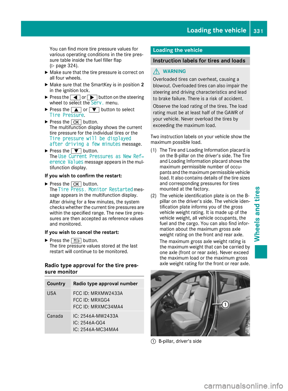
(1) The Tire and Loading Information placard is on the B-pillar on the driver's side. The Tire
and Loading Information placard shows the
maximum permissible number of occu-
pants and the maximum permissible vehicle
load. It also contains details of the tire sizes
and corresponding pressures for tires
mounted at the factory.
(2) The vehicle identification plate is on the B- pillar on the driver's side. The vehicle iden-
tification plate informs you of the gross
vehicle weight rating. It is made up of the
vehicle weight, all vehicle occupants, the
fuel and the cargo. You can also find infor-
mation about the maximum gross axle
weight rating on the front and rear axle.
The maximum gross axle weight rating is
the maximum weight that can be carried by
one axle (front or rear axle). Never exceed
the maximum load or the maximum gross
axle weight rating for the front or rear axle.
:B-pillar, driver's side
Loading the vehicle331
Wheels and tires
Z
Page 342 of 366
tem and optional equipment if these are instal-
led in the vehicle, but does not include passen-
gers or luggage.
Maximum load rating
The maximum tire load is the maximum permis-
sible weight in kilograms or lbs for which a tire is approved.
Maximum permissible tire pressure
Maximum permissible tire pressure for one tire.
Maximum load on one tire
Maximum load on one tire. This is calculated by
dividing the maximum axle load of one axle by
two.
PSI (pounds per square inch)
A standard unit of measure for tire pressure.
Aspect ratio
Relationship between tire height and tire width
in percent.
Tire pressure
This is pressure inside the tire applying an out-
ward force to each square inch of the tire's sur-
face. The tire pressure is specified in pounds per
square inch (psi), in kilopascal (kPa) or in bar.
The tire pressure should only be corrected whenthe tires are cold.
Cold tire pressure
The tires are cold:
Rif the vehicle has been parked with the tires
out of direct sunlight for at least three hours
and
Rif the vehicle has not been driven further than
1 mile (1.6 km)
Tread
The part of the tire that comes into contact with
the road.
Bead
The tire bead ensures that the tire sits securely
on the wheel. There are several steel wires in the
bead to prevent the tire from coming loose from
the wheel rim.
Sidewall
The part of the tire between the tread and the
bead.
Weight of optional extras
The combined weight of those optional extras
that weigh more than the replaced standard
parts and more than 2.3 kg (5 lbs). These
optional extras, such as high-performance
brakes, level control, a roof rack or a high-per-
formance battery, are not included in the curb
weight and the weight of the accessories.
TIN (Tire Identification Number)
This is a unique identifier which can be used by
a tire manufacturer to identify tires, for example
for a product recall, and thus identify the pur-
chasers. The TIN is made up of the manufactur- er's identity code, tire size, tire type code and
the manufacturing date.
Load bearing index
The load bearing index (also load index) is a code
that contains the maximum load bearing capa-
city of a tire.
Traction
Traction is the result of friction between the tires
and the road surface.
TWR (Tongue Weight Rating)
The TWR specifies the maximum permissible
weight that the ball coupling of the trailer tow
hitch can support.
Treadwear indicators
Narrow bars (tread wear bars) that are distrib-
uted over the tire tread. If the tire tread is level
with the bars, the wear limit of áin (1.6 mm)
has been reached.
Occupant distribution
The distribution of occupants in a vehicle at their
designated seating positions.
Total load limit
Nominal load and luggage load plus 68 kg
(150 lbs) multiplied by the number of seats in
the vehicle.
340All about wheels an d tires
Wheels and tires
Page 344 of 366

XVehicles with KEYLESS-GO:open the driv-
er's door.
The on-board electronics now have status 0.
This is the same as the SmartKey having been
removed.
XVehicles with KEYLESS-GO: remove the
Start/Stop button from the ignition lock
(
Ypage 125).
XMake sure that the engine cannot be started
via your smartphone (Ypage 127).
XIf included in the vehicle equipment, remove
the tire-change tool kit from the vehicle.
XSafeguard the vehicle against rolling away.
iApart from certain country-specific varia-
tions, vehicles are not equipped with a tire-
change tool kit. For information on which
tools are required to perform a wheel change
on your vehicle, consult an authorized
Mercedes-Benz Center.
Necessary tire-changing tools can include, for example:
RJack
RWheel chock
RLug wrench
Securing the vehicle to prevent it from
rolling away
If your vehicle is equipped with a wheel chock, itcan be found in the tire-change tool kit
(
Ypage 306).
The folding wheel chock is an additional safety
measure to prevent the vehicle from rolling
away, for example when changing a wheel.
XFold both plates upwards :.
XFold out lower plate;.
XGuide the lugs on the lower plate fully into the
openings in base plate =.
XPlace chocks or other suitable items under
the front and rear of the wheel that is diago-
nally opposite the wheel you wish to change.
Raising the vehicle
GWARNING
If you do not position the jack correctly at the
appropriate jacking point of the vehicle, the
jack could tip over with the vehicle raised.
There is a risk of injury.
Only position the jack at the appropriate jack-
ing point of the vehicle. The base of the jack
must be positioned vertically, directly under
the jacking point of the vehicle.
!The jack is designed exclusively for jacking
up the vehicle at the jacking points. Other-
wise, your vehicle could be damaged.
Observe the following when raising the vehi-
cle:
RTo raise the vehicle, only use the vehicle-spe-
cific jack that has been tested and approved
by Mercedes-Benz. If used incorrectly, the
jack could tip over with the vehicle raised.
RThe jack is designed only to raise and hold the
vehicle for a short time while a wheel is being
changed. It must not be used for performing
maintenance work under the vehicle.
RAvoid changing the wheel on uphill and down- hill slopes.
RBefore raising the vehicle, secure it from roll-
ing away by applying the parking brake and
inserting wheel chocks. Do not disengage the
parking brake while the vehicle is raised.
RThe jack must be placed on a firm, flat and
non-slip surface. On a loose surface, a large,
flat, load-bearing underlay must be use
d. On a
342Changing a wheel
Wheels and tires
Page 346 of 366
XUnscrew the uppermost wheel bolt com-
pletely.
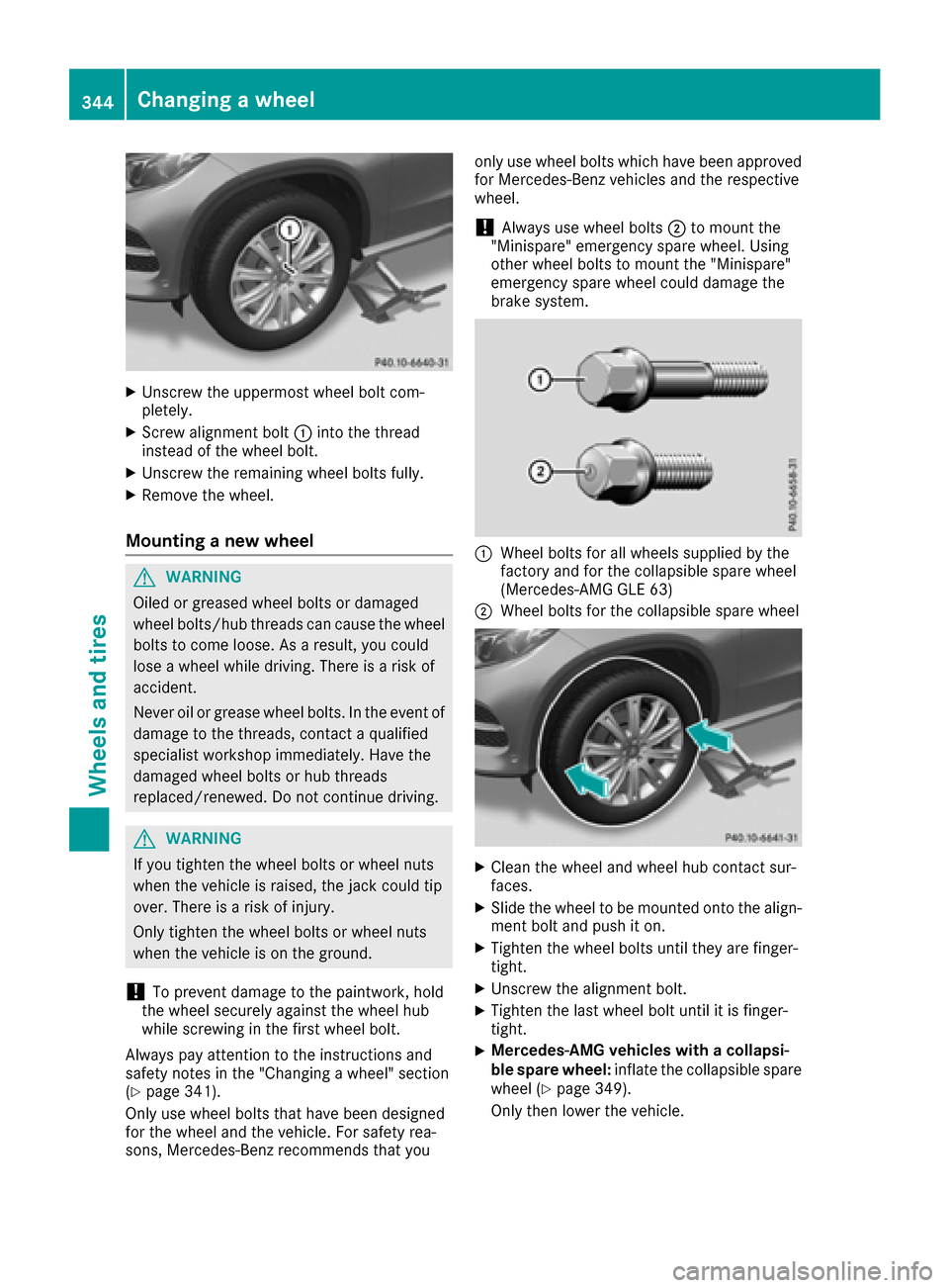
XScrew alignment bolt:into the thread
instead of the wheel bolt.
XUnscrew the remaining wheel bolts fully.
XRemove the wheel.
Mounting a new wheel
GWARNING
Oiled or greased wheel bolts or damaged
wheel bolts/hub threads can cause the wheel bolts to come loose. As a result, you could
lose a wheel while driving. There is a risk of
accident.
Never oil or grease wheel bolts. In the event of
damage to the threads, contact a qualified
specialist workshop immediately. Have the
damaged wheel bolts or hub threads
replaced/renewed. Do not continue driving.
GWARNING
If you tighten the wheel bolts or wheel nuts
when the vehicle is raised, the jack could tip
over. There is a risk of injury.
Only tighten the wheel bolts or wheel nuts
when the vehicle is on the ground.
!To prevent damage to the paintwork, hold
the wheel securely against the wheel hub
while screwing in the first wheel bolt.
Always pay attention to the instructions and
safety notes in the "Changing a wheel" section
(
Ypage 341).
Only use wheel bolts that have been designed
for the wheel and the vehicle. For safety rea-
sons, Mercedes-Benz recommends that you only use wheel bolts which have been approved
for Mercedes-Benz vehicles and the respective
wheel.
!Always use wheel bolts
;to mount the
"Minispare" emergency spare wheel. Using
other wheel bolts to mount the "Minispare"
emergency spare wheel could damage the
brake system.
:Wheel bolts for all wheels supplied by the
factory and for the collapsible spare wheel
(Mercedes-AMG GLE 63)
;Wheel bolts for the collapsible spare wheel
XClean the wheel and wheel hub contact sur-
faces.
XSlide the wheel to be mounted onto the align-
ment bolt and push it on.
XTighten the wheel bolts until they are finger-
tight.
XUnscrew the alignment bolt.
XTighten the last wheel bolt until it is finger-
tight.
XMercedes-AMG vehicles with a collapsi-
ble spare wheel: inflate the collapsible spare
wheel (
Ypage 349).
Only then lower the vehicle.
344Changing a wheel
Wheels and tires
Page 349 of 366
tion reliably. Only restart the tire pressure loss
warning system or tire pressure monitor when
the defective wheel has been replaced with a
new wheel.
Vehicles with tire pressure monitor:after
mounting an emergency spare wheel, the sys-
tem may still display the tire pressure of the
removed wheel for a few minutes. The value dis-
played for the mounted emergency spare wheel
is not the same as the current tire pressure of
the emergency spare wheel.
Removing/stowing the emergency
spare wheel
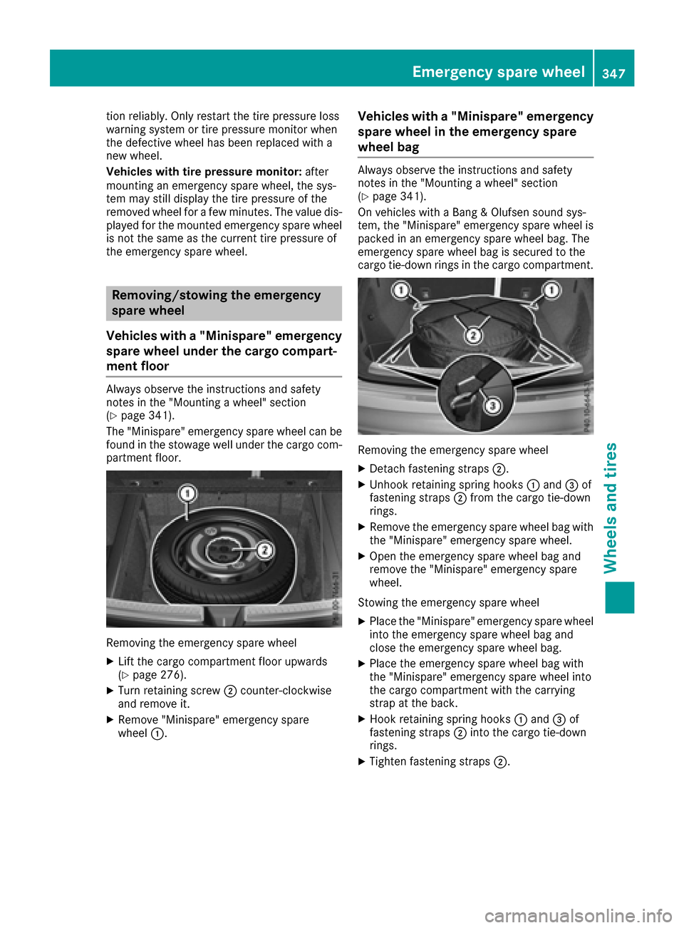
Vehicles with a "Minispare" emergency
spare wheel under the cargo compart-
ment floor
Always observe the instructions and safety
notes in the "Mounting a wheel" section
(
Ypage 341).
The "Minispare" emergency spare wheel can be
found in the stowage well under the cargo com-
partment floor.
Removing the emergency spare wheel
XLift the cargo compartment floor upwards
(Ypage 276).
XTurn retaining screw ;counter-clockwise
and remove it.
XRemove "Minispare" emergency spare
wheel :.
Vehicles with a "Minispare" emergency
spare wheel in the emergency spare
wheel bag
Always observe the instructions and safety
notes in the "Mounting a wheel" section
(
Ypage 341).
On vehicles with a Bang & Olufsen sound sys-
tem, the "Minispare" emergency spare wheel is packed in an emergency spare wheel bag. The
emergency spare wheel bag is secured to the
cargo tie-down rings in the cargo compartment.
Removing the emergency spare wheel
XDetach fastening straps ;.
XUnhook retaining spring hooks :and =of
fastening straps ;from the cargo tie-down
rings.
XRemove the emergency spare wheel bag with
the "Minispare" emergency spare wheel.
XOpen the emergency spare wheel bag and
remove the "Minispare" emergency spare
wheel.
Stowing the emergency spare wheel
XPlace the "Minispare" emergency spare wheel
into the emergency spare wheel bag and
close the emergency spare wheel bag.
XPlace the emergency spare wheel bag with
the "Minispare" emergency spare wheel into
the cargo compartment with the carrying
strap at the back.
XHook retaining spring hooks :and =of
fastening straps ;into the cargo tie-down
rings.
XTighten fastening straps ;.
Emergency sparewheel347
Wheels an d tires
Z
Page 350 of 366

Mercedes-AMG vehicles with a collaps-
ible spare wheel under the cargo com-
partment floor
!Only place the collapsible spare wheel in the
vehicle when it is dry. Otherwise, moisture
may get into the vehicle.
Always observe the instructions and safety
notes in the "Mounting a wheel" section
(
Ypage 341).
The collapsible spare wheel can be found in the
stowage well under the cargo compartment
floor.
Removing the emergency spare wheel
XLift the cargo compartment floor upwards
(Ypage 276).
XUnscrew retaining screw ;counter-clock-
wise.
XRemove collapsible spare wheel :from the
spare wheel well.
Inflating the collapsible spare wheel
(
Ypage 349).
Take the following steps to stow a used collaps- ible spare wheel. Otherwise, it will not fit into the
spare wheel well. Mercedes-Benz recommends
that you have this work performed at a qualified
specialist workshop, e.g. at an authorized
Mercedes-Benz Center.
Stowing the emergency spare wheel
XUnscrew the valve cap from the valve.
XIf possible, unscrew the valve insert from the
valve and release the air.
iFully deflating the tires can take a few
minutes.
XScrew the valve insert back into the valve.
XScrew the valve cap back on.
XLay collapsible spare wheel :in the emer-
gency spare wheel well.
XScrew in retaining screw ;clockwise in the
collapsible emergency wheel to the stop.
XSwing the cargo compartment floor down
(Ypage 276).
Mercedes-AMG vehicles with a collaps-
ible spare wheel in the emergency
spare wheel bag
Always observe the instructions and safety
notes in the "Mounting a wheel" section
(
Ypage 341).
On Mercedes-AMG vehicles with a Bang & Oluf-
sen sound system, the collapsible spare wheel is packed in an emergency spare wheel bag. The
emergency spare wheel bag is secured to the
cargo tie-down rings in the cargo compartment.
Removing the emergency spare wheel
XUnhook retaining spring hooks :of fasten-
ing strap ;from the cargo tie-down rings.
XRemove the emergency spare wheel bag with
the emergency collapsible spare wheel.
XOpen the bag and remove the emergency col-
lapsible spare wheel.
Inflating the collapsible spare wheel
(
Ypage 349).
Stowing the emergency spare wheel
XPlace the collapsible spare wheel into the
emergency spare wheel bag and close the
emergency spare wheel bag.
XPlace the emergency spare wheel bag with
the collapsible spare wheel into the cargo
compartment with the carrying strap at the
back.
XHook retaining spring hooks :of fastening
strap ;into the cargo tie-down rings.
XTighten fastening strap ;.
348Emergency spare wheel
Wheels and tires