2017 MERCEDES-BENZ GLA SUV tailgate
[x] Cancel search: tailgatePage 204 of 369
Activating/deactivating the reversing
camera X
To activate: make sure that the key is in
position 2in the ignition lock.
X Make sure that the Activation by R gear
Activation by R gear
function is selected in the multimedia system; see the Digital Owner's Manual.
X Engage reverse gear.
The area behind the vehicle is shown with
guide lines in the multimedia system display.
The image from the reversing camera is avail-
able throughout the manoeuvring process.
X To switch the function mode for vehicles
with trailer tow hitch: using the controller,
select symbol :for the "Reverse parking"
function or symbol ;for "Coupling up a
trailer".
The symbol of the selected function is high-
lighted.
To deactivate: the reversing camera deacti-
vates if you shift the transmission to jor after
driving forwards a short distance.
Messages in the multimedia system dis-
play The reversing camera may show a distorted view
of obstacles, show them incorrectly or not at all. Obstacles are not shown by the reversing cam-
era in the following locations:
R very close to the rear bumper
R under the rear bumper
R in the area immediately above the recessed
tailgate handle
! Objects not at ground level may appear to
be further away than they actually are, e.g.:
R the bumper of a parked vehicle
R the drawbar of a trailer R
the ball coupling of a trailer tow hitch
R the rear section of an HGV
R a slanted post
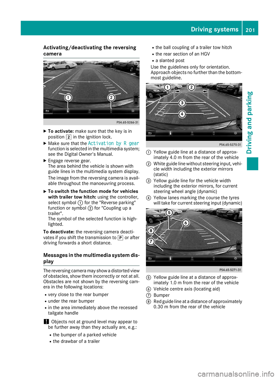
Use the guidelines only for orientation.
Approach objects no further than the bottom-
most guideline. :
Yellow guide line at a distance of approx-
imately 4.0 m from the rear of the vehicle
; White guide line without steering input, vehi-
cle width including the exterior mirrors
(static)
= Yellow guide line for the vehicle width
including the exterior mirrors, for current
steering wheel angle (dynamic)
? Yellow lanes marking the course the tyres
will take for current steering input (dynamic) A
Yellow guide line at a distance of approx-
imately 1.0 m from the rear of the vehicle
B Vehicle centre axis (locating aid)
C Bumper
D Red guide line at a distance of approximately
0.30 m from the rear of the vehicle Driving systems
201Driving and parking Z
Page 208 of 369
R
under the front bumper
R very close to the front bumper
R very close to the rear bumper
R under the rear bumper
R in the area immediately above the recessed
handle on the boot lid
R very close to the exterior mirrors
You are responsible for safety at all times and
must always pay attention to your immediate
surroundings when parking and manoeuvring.
This applies to the areas behind, in front of and
beside the vehicle. You could otherwise endan-
ger yourself and others.
The 360° camera will not function or will func-
tion only to a limited extent:
R if the doors are open
R if the exterior mirrors are folded in
R if the tailgate is open
R in heavy rain, snow or fog
R at night or in very dark places
R if the cameras are exposed to very bright light
R if the area is lit by fluorescent lamps or LED
lighting (the display may flicker)
R if there is a sudden change in temperature,
e.g. when driving into a heated garage in win- ter
R if the camera lenses are dirty or covered
R if the vehicle components in which the cam-
eras are fitted are damaged: In this event,
have the camera position and setting checked at a qualified specialist workshop
Do not use the 360° camera under such cir-
cumstances. You could otherwise injure others
or damage objects when parking the vehicle.
Activation conditions The 360° camera image can be displayed if:
R your vehicle is equipped with a 360° camera
R COMAND Online is switched on; see the sep-
arate COMAND Online operating instructions
R the 360° camera 360° camera function is activated Activating the 360° camera using the
SYS button X
Press the Wbutton for longer than 2 sec-
onds; see the separate COMAND Online oper-
ating instructions.
The following appears depending on whether
gear hork is selected:
R full-screen view with image from the front
camera
R full-screen view with image from the revers-
ing camera
Activating the 360° camera using
COMAND Online X
Press the Wbutton, see the separate
COMAND Online operating Instructions.
X Select System System by turning cVdthe COMAND
controller and press Wto confirm.
X Select 360°
360°camera
camera and press Wto confirm.
The following appears depending on whether
gear hork is selected:
R a split screen with top view and the image
from the front camera or
R a split screen with top view and the image
from the rear view camera
For further information on the COMAND con-
troller; see the separate COMAND Online oper-
ating instructions.
Switching on the 360° camera using
reverse gear You can show images from the 360° camera
automatically by engaging reverse gear.
X Make sure that the key is in position 2in the
ignition lock.
X Make sure that the Activation by R gear Activation by R gear
setting is active in COMAND Online, see the
separate COMAND Online operating instruc-
tions.
X To show the 360° camera image: engage
reverse gear.
The area behind the vehicle is shown in the
COMAND display in split-screen mode:
R vehicle with guide lines
R top view of the vehicle Driving systems
205Driving and parking Z
Page 264 of 369
Display messages
Possible causes/consequences and
M
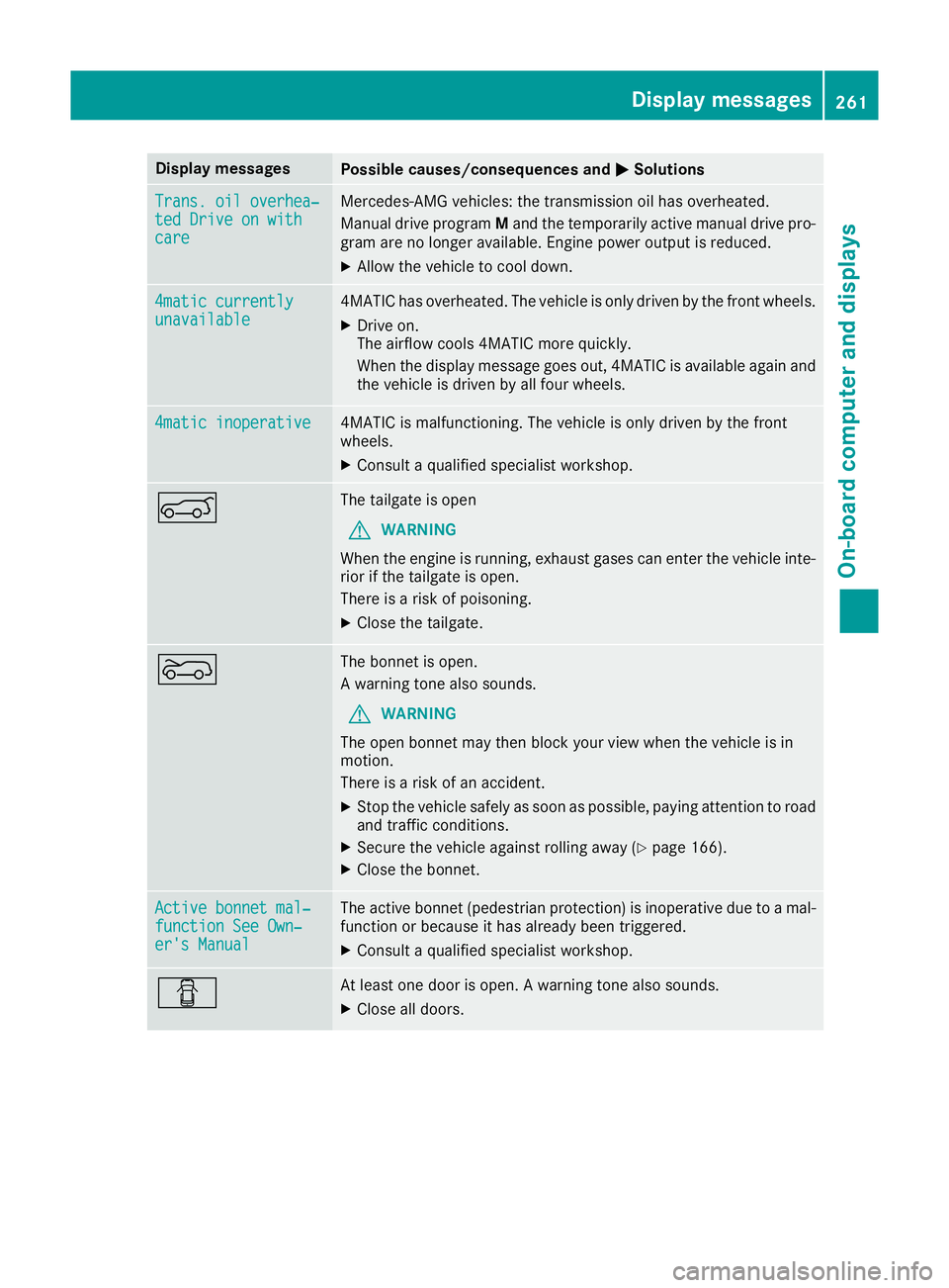
MSolutions Trans. oil overhea‐
Trans. oil overhea‐
ted Drive on with ted Drive on with
care care Mercedes-AMG vehicles: the transmission oil has overheated.
Manual drive program Mand the temporarily active manual drive pro-
gram are no longer available. Engine power output is reduced.
X Allow the vehicle to cool down. 4matic currently
4matic currently
unavailable unavailable 4MATIC has overheated. The vehicle is only driven by the front wheels.
X Drive on.
The airflow cools 4MATIC more quickly.
When the display message goes out, 4MATIC is available again and
the vehicle is driven by all four wheels. 4matic inoperative 4matic inoperative 4MATIC is malfunctioning. The vehicle is only driven by the front
wheels.
X Consult a qualified specialist workshop. A The tailgate is open
G WARNING
When the engine is running, exhaust gases can enter the vehicle inte- rior if the tailgate is open.
There is a risk of poisoning.
X Close the tailgate. ? The bonnet is open.
A warning tone also sounds.
G WARNING
The open bonnet may then block your view when the vehicle is in
motion.
There is a risk of an accident.
X Stop the vehicle safely as soon as possible, paying attention to road
and traffic conditions.
X Secure the vehicle against rolling away (Y page 166).
X Close the bonnet. Active bonnet mal‐ Active bonnet mal‐
function See Own‐ function See Own‐
er's Manual er's Manual The active bonnet (pedestrian protection) is inoperative due to a mal-
function or because it has already been triggered.
X Consult a qualified specialist workshop. C At least one door is open. A warning tone also sounds.
X Close all doors. Display
messages
261On-board computer and displays Z
Page 291 of 369

Loading guidelines
G
WARNING
If objects, luggage or loads are not secured or not secured sufficiently, they could slip, tip
over or be flung around and thereby hit vehicle
occupants. There is a risk of injury, especially when braking or abruptly changing directions.
Always store objects so that they cannot be
flung around. Secure objects, luggage or
loads against slipping or tipping before the
journey. G
WARNING
Combustion engines emit poisonous exhaust
gases such as carbon monoxide. If the tailgate is open when the engine is running, particu-
larly if the vehicle is moving, exhaust fumes
could enter the passenger compartment.
There is a risk of poisoning.
Turn off the engine before opening the tail-
gate. Never drive with the tailgate open. G
WARNING
The exhaust tail pipe and tail pipe trim can
become very hot. If you come into contact
with these parts of the vehicle, you could burn
yourself. There is a risk of injury.
Always be particularly careful around the
exhaust tail pipe and the tail pipe trim. Allow
these components to cool down before touch-
ing them.
The handling characteristics of a laden vehicle
are dependent on the distribution of the load
within the vehicle.
Observe the following notes on loading and
transporting a load:
R never exceed the maximum permissible gross
vehicle weight or the permissible axle loads
for the vehicle (including occupants).
R the luggage compartment is the preferred
place to store objects.
R position heavy loads as far forwards as pos-
sible and as low down in the luggage com-
partment as possible. R
the load must not protrude above the upper
edge of the seat backrests.
R always place the load against the rear or front
seat backrests. Make sure that the seat
backrests are securely locked into place.
R always place the load behind unoccupied
seats if possible.
R use the lashing eyelets and the luggage nets
to transport loads and luggage.
R only use lashing eyelets and fastening com-
ponents that are suitable for the weight and
size of the load.
R the maximum load capacity of the stowage
well under the luggage compartment floor is
25 kg.
R secure the load with sufficiently strong and
wear-resistant lashing material. Pad sharp
edges for protection.
! Do not position the load on one part of the
folding luggage compartment floor only. The
maximum load capacity of the folding luggage compartment floor is 100 kg. Spread the
weight evenly to avoid damaging the luggage
compartment floor. Place a solid board under the load if necessary. Please note that the
load on the luggage compartment floor will be increased when the load is lashed down. Stowage areas
Stowage compartments
Important safety notes G
WARNING
If you transport objects in the vehicle interior and these are not adequately secured, they
could slip or be flung around and thereby
strike vehicle occupants. In addition, cup
holders, open stowage spaces and mobile
phone brackets may not always be able to
hold the objects placed in them in the event of an accident. There is a risk of injury, particu-
larly in the event of sharp braking or sudden
changes of direction. 288
Stowage areasStowing and features
Page 297 of 369
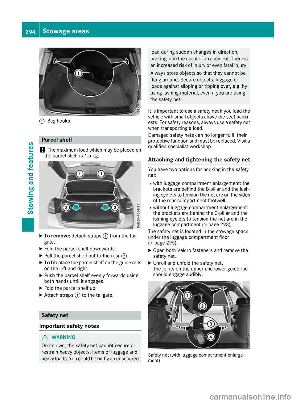
:
Bag hooks Parcel shelf
! The maximum load which may be placed on
the parcel shelf is 1.5 kg. X
To remove: detach straps :from the tail-
gate.
X Fold the parcel shelf downwards.
X Pull the parcel shelf out to the rear ;.
X To fit: place the parcel shelf on the guide rails
on the left and right.
X Push the parcel shelf evenly forwards using
both hands until it engages.
X Fold the parcel shelf up.
X Attach straps :to the tailgate. Safety net
Important safety notes G
WARNING
On its own, the safety net cannot secure or
restrain heavy objects, items of luggage and
heavy loads. You could be hit by an unsecured load during sudden changes in direction,
braking or in the event of an accident. There is
an increased risk of injury or even fatal injury.
Always store objects so that they cannot be
flung around. Secure objects, luggage or
loads against slipping or tipping over, e.g. by
using lashing material, even if you are using
the safety net.
It is important to use a safety net if you load the
vehicle with small objects above the seat backr- ests. For safety reasons, always use a safety netwhen transporting a load.
Damaged safety nets can no longer fulfil their
protective function and must be replaced. Visit a
qualified specialist workshop.
Attaching and tightening the safety net You have two options for hooking in the safety
net:
R with luggage compartment enlargement: the
brackets are behind the B‑ pillar and the lash-
ing eyelets to tension the net are on the sides of the rear-compartment footwell.
R without luggage compartment enlargement:
the brackets are behind the C-pillar and the
lashing eyelets to tension the net are in the
luggage compartment (Y page 293).
The safety net is located in the stowage space
under the luggage compartment floor
(Y page 295).
X Open both Velcro fasteners and remove the
safety net.
X Unroll and unfold the safety net.
The joints on the upper and lower guide rod
should engage audibly. Safety net (with luggage compartment enlarge-
ment) 294
Stowage areasStowing and features
Page 298 of 369
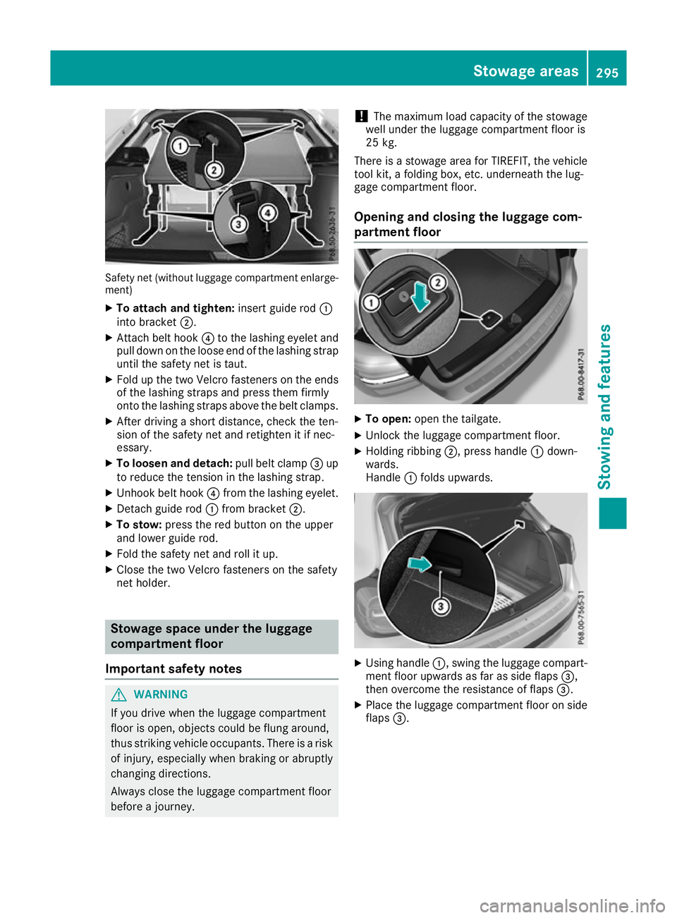
Safety net (without luggage compartment enlarge-
ment)
X To attach and tighten: insert guide rod:
into bracket ;.
X Attach belt hook ?to the lashing eyelet and
pull down on the loose end of the lashing strap until the safety net is taut.
X Fold up the two Velcro fasteners on the ends
of the lashing straps and press them firmly
onto the lashing straps above the belt clamps.
X After driving a short distance, check the ten-
sion of the safety net and retighten it if nec-
essary.
X To loosen and detach: pull belt clamp=up
to reduce the tension in the lashing strap.
X Unhook belt hook ?from the lashing eyelet.
X Detach guide rod :from bracket ;.
X To stow: press the red button on the upper
and lower guide rod.
X Fold the safety net and roll it up.
X Close the two Velcro fasteners on the safety
net holder. Stowage space under the luggage
compartment floor
Important safety notes G
WARNING
If you drive when the luggage compartment
floor is open, objects could be flung around,
thus striking vehicle occupants. There is a risk of injury, especially when braking or abruptly
changing directions.
Always close the luggage compartment floor
before a journey. !
The maximum load capacity of the stowage
well under the luggage compartment floor is
25 kg.
There is a stowage area for TIREFIT, the vehicle tool kit, a folding box, etc. underneath the lug-
gage compartment floor.
Opening and closing the luggage com-
partment floor X
To open: open the tailgate.
X Unlock the luggage compartment floor.
X Holding ribbing ;, press handle :down-
wards.
Handle :folds upwards. X
Using handle :, swing the luggage compart-
ment floor upwards as far as side flaps =,
then overcome the resistance of flaps =.
X Place the luggage compartment floor on side
flaps =. Stowage areas
295Stowing and features Z
Page 299 of 369
Roof carrier
Important safety notes G
WARNING
When a load is transported on the roof, the
vehicle's centre of gravity rises and the han-
dling changes. If you exceed the maximum
roof load, the handling as well as steering and braking characteristics are severely affected.
There is a risk of an accident.
Always observe the maximum roof load and
adapt your driving style.
! Mercedes-Benz recommends that you only
use roof carriers that have been tested and
approved for Mercedes-Benz vehicles. This
helps to prevent damage to the vehicle.
Position the load on the roof carrier in such a way that the vehicle will not sustain damage
even when it is in motion.
Ensure that, depending on the vehicle's
equipment, you can raise the panorama slid-
ing sunroof fully and open the tailgate fully
when the roof carrier is fitted.
You will find information on the maximum roof
load in the "Technical data" section
(Y page 358).
An incorrectly secured roof carrier or roof load
may become detached from the vehicle. You
must therefore ensure that you observe the roof
carrier manufacturer's installation instructions.
Attaching the roof carrier X
Secure the roof carrier to the roof rails. In
doing so, observe the manufacturer's instal-
lation instructions. Features
Cup holders
Important safety notes G
WARNING
The cup holder cannot secure a drinks con-
tainer in place during a journey. If you use a
cup holder during a journey, the drinks con- tainer could be flung around and liquid could
be spilt. Vehicle occupants could come into
contact with the liquid and, in particular, be
scalded by hot liquid. You could be distracted
from the traffic situation and lose control of
the vehicle. There is a risk of an accident and
injury.
Only use the cup holder when the vehicle is
stationary. Only place containers of a suitable size in the cup holder. Seal the container, in
particular when it contains hot liquid. G
WARNING
If you transport objects in the vehicle interior and these are not adequately secured, they
could slip or be flung around and thereby
strike vehicle occupants. In addition, cup
holders, open stowage spaces and mobile
phone brackets may not always be able to
hold the objects placed in them in the event of an accident. There is a risk of injury, particu-
larly in the event of sharp braking or sudden
changes of direction.
R Always stow objects in such a way that they
cannot be tossed about in these or similar
situations.
R Always make sure that objects do not proj-
ect from stowage spaces, luggage nets or
stowage nets.
R Ensure that closable stowage spaces are
shut before beginning your journey.
R Always stow and secure heavy, hard, poin-
ted, sharp-edged, fragile or outsize objects
in the load compartment.
! Only use the cup holders for containers of
the right size and which have lids. The drinks
could otherwise spill.
Observe the loading guidelines (Y page 288).
The stowage compartments in the doors provide
space for bottles:
R front: capacity up to 1.0 l
R rear: capacity up to 0.5 l 296
FeaturesStowing and features
Page 319 of 369
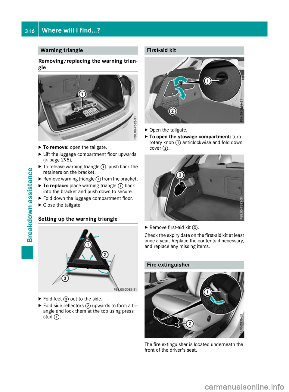
Warning triangle
Removing/replacing the warning trian-
gle X
To remove: open the tailgate.
X Lift the luggage compartment floor upwards
(Y page 295).
X To release warning triangle :, push back the
retainers on the bracket.
X Remove warning triangle :from the bracket.
X To replace: place warning triangle :back
into the bracket and push down to secure.
X Fold down the luggage compartment floor.
X Close the tailgate.
Setting up the warning triangle X
Fold feet =out to the side.
X Fold side reflectors ;upwards to form a tri-
angle and lock them at the top using press
stud :. First-aid kit
X
Open the tailgate.
X To open the stowage compartment: turn
rotary knob :anticlockwise and fold down
cover ;. X
Remove first-aid kit =.
Check the expiry date on the first-aid kit at least once a year. Replace the contents if necessary,and replace any missing items. Fire extinguisher
The fire extinguisher is located underneath the
front of the driver's seat. 316
Where will I find...?Breakdown assistance