2017 MERCEDES-BENZ G-Class door lock
[x] Cancel search: door lockPage 208 of 286
XTo lock:insert the mechanical key into the
lock (Ypage 64) and turn it 90° clockwise to
position 2.
XTo unlock: insert the mechanical key into the
lock (Ypage 64 )and turn it 90° counter-
clockwise to position 1.
The glove bo xcan onlybel ocked and unlocked
using the mechanical key.
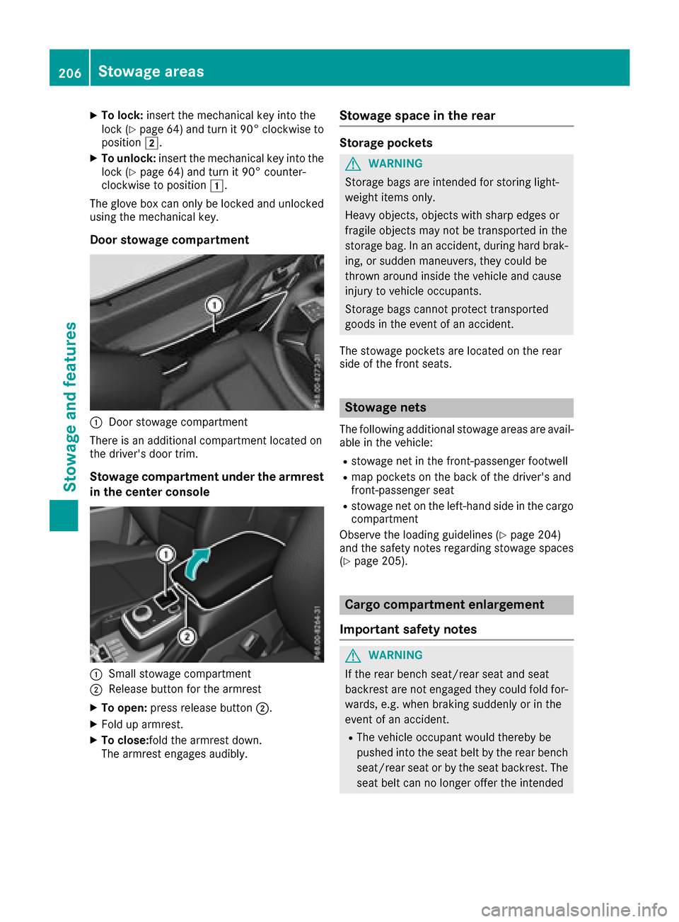
Door stowage compartment
:Door stowag ecompartment
There is an additional compartment locate don
the driver's door trim.
Stowage compartmen tundert he armrest
in the centerc onsole
:Small stowagecompartment
;Releas ebutton for the armrest
XTo open: press release button ;.
XFolduparmrest.
XTo close:foldt he armrestdown.
The armreste ngages audibly.
Stowage spaceint he rear
Storage pockets
GWARNING
Storage bags are intende dfor storing light-
weight items only.
Heavy objects, objects with sharp edges or
fragile objects mayn ot be transported in the
storag ebag.Inana ccident, during hard brak-
ing ,ors uddenmaneuvers,t hey could be
thrown around insid ethe vehicl eand cause
injury to vehicl eoccupants.
Storage bags canno tprotect transported
goods in the event of an accident.
The stowag epockets are locate donthe rear
side of the front seats.
Stowage nets
The following additional stowag eareas are avail-
able in the vehicle:
Rstowag enet in the front-passenger footwell
Rmapp ockets on the back of the driver'sa nd
front-passenger seat
Rstowag enet on the left-hand side in the cargo
compartment
Observe the loading guideline s(
Ypage 204)
and the safety notes regarding stowag espaces
(
Ypage 205).
Carg ocom partmen tenlargement
Important safety notes
GWARNING
If the rearb ench seat/rea rseata nd seat
backres tare not engaged they could foldf or-
wards ,e.g.w henb raking suddenl yorinthe
event of an accident.
RThe vehicl eoccupant woul dthereb ybe
pushedi nto the sea tbeltbyt he rearb ench
seat/rea rseatorb ythe sea tbackrest. The
sea tbeltc an no longer offert he intended
206Stowage areas
Stowageand featur es
Page 215 of 286
The cigarettelighter socket can be also used
(Ypage 212). This is the case even if the Smart-
Key has been removed from the ignition lock.
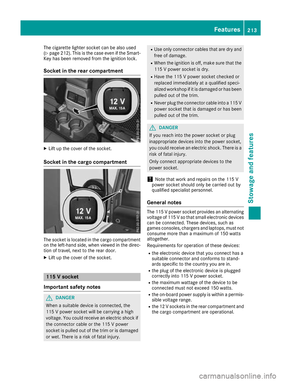
Socket in the rear compartment
XLift up the cover of the socket.
Socket in the cargo compartment
The socket is located in the cargo compartment
on the left-hand side, when viewed in the direc-
tion of travel, next to the rear door.
XLift up the cover of the socket.
115 Vsocket
Important safety notes
GDANGER
When asuitable device is connected, the
115 Vpower socket will be carrying ahigh
voltage. You could receive an electric shock if the connector cable or the 115 Vpower
socket is pulled out of the trim or is damaged
or wet. There is arisk of fatal injury.
RUse only connector cables that are dry and
free of damage.
RWhen the ignition is off, make sure that the
115 Vpower socket is dry.
RHave the 115 Vpower socket checked or
replaced immediately at aqualified speci-
alized workshop if it is damaged or has been
pulled out of the trim.
RNever plug the connector cable into a115 V
power socket that is damaged or has been
pulled out of the trim.
GDANGER
If you reach into the power socket or plug
inappropriate devices into the power socket,
you could receive an electric shock.T here is a
risk of fatal injury.
Only connect appropriate devices to the
power socket.
!Note that work and repairs on the 115 V
power socket should only be carried out by
qualified specialist personnel.
General notes
The 115 Vpower socket provides an alternating
voltage of 115 Vsothat small electronic devices
can be connected. These devices, such as
games consoles, chargers and laptops, must not consume more than amaximum of 150 watts
altogether.
Requirements for operation of these devices:
Rthe electronic device that you connect has a
suitable connector and conforms to stand-
ards specific to the country you are in.
Rthe plug of the electronic device is plugged
correctly into 115 Vpower socket.
Rthe maximum wattage of the device to be
connected must not exceed 150 watts.
Rthe on-board power supply is within apermis-
sible voltage range.
Rthe 12 Vsocketsint he rear compartment and
the cargo compartment are operational.
Features213
Stowage and features
Z
Page 222 of 286
Mercedes-BenzCustomer Assistanc eCenter
at 1-800-FOR-MERCedes (1-800-367-6372)
or 1-866-990-9007
You will be asked for your password.
The next time you are inside the vehicle and you
switch on the ignition, the Doors Locked
Remotelymessage appears in the multifunction
display.
Alternatively, the vehicle can be locked via:
Rthe Internet, under the "Owners Online" sec-
tion
Rtelephone applications (e.g. for iPhone®,
Android™)
To do this, you will need your identification num-
ber and password.
Stolen vehicle recovery service
If your vehicle has been stolen:
XNotify the police.
The police will issue anumbered incident
report.
XThis number will be forwarded to the
Mercedes-BenzC ustomer Assistanc eCenter
together with your PIN.
The Mercedes-BenzC ustomer Assistance
Center then tries to locate the system. The
Mercedes-BenzC ustomer Assistanc eCenter
contacts you and the local law enforcement
agency if the vehicle is located.
However, only the law enforcement agency is
informed of the location of the vehicle.
If the anti-theft alarm system is activated for
longer than 30 seconds, the Mercedes-Benz
Customer Assistanc eCenter is automatically
notified.
Vehicle Health Check
With the Vehicle Health Check, the Customer
Assistanc eCenter can provide improved sup-
port for problems with your vehicle. During an
existing call, vehicle data is transferred to the
Customer Assistanc eCenter.
The customer service representative can use
the received data to decide what kind of assis-
tance is required. You are then, for example,
guided to the nearest Mercedes-BenzS ervice
Center or arecovery vehicle is called.
If vehicle data need to be transferred during an
Info call or aRoadside Assistanc ecall, this is
initiated by the Customer Assistanc eCenter. You will see the
Roadside Assistance Con‐
nectedmessage in the display.Ift he Vehicle
Health Check can be started, the RequestforVehicle Diagnostics Received Startvehicle diagnostics?message appears in
the display.
XPress the Yesbutton to confirm the message.
XWhen the Vehicle Diagnostics PleaseStart Ignitionmessage appears: turn the
SmartKey to position 2in the ignition lock
(
Ypage 104).
XIf the Please follow the instructionsreceivedbyphoneandmoveyourvehi‐cle to asafe position.message
appears: please follow the instructions
received by phone and move your vehicle to a
safe position.
The message in the display disappears.
The vehicle operating state check begins. You
will see the Vehicle Diagnostics Active
message.
If you select Cancel
,the Vehicle Health
Check is canceled completely.
When the check is complete, the Sending
vehicle diagnostics data. (Voice con‐nection may be interrupted duringdatatransfer)message appears. The vehicle
data can now be sent.
XPress the OKbutton to confirm the message.
The voice connection with the Customer
Assistanc eCenter is terminated.
You will see the Vehicle diagnosis:
Transferring data...message.
The vehicle data is sent to the Customer
Assistanc eCenter.
Depending on what the customer service rep-
resentative agreed with you, the voice connec-
tion is re-established after the transfer is com-
plete. If necessary, you will be contacted at a
later time by another means, e.g. by e-mail or
phone.
Another function of the Vehicle Health Check is
the transfer of service data to the Customer
Assistanc eCenter. If aservice is due, the display
shows amessage to this effect together with
information about any special offers at your
workshop.
This information can also be called up under
"Owners Online" at http://www.mbusa.com.
Information on the data stored in the vehicle
(
Ypage 28).
220Features
Stowage and features
Page 224 of 286

Alternatively,you can cal lthe following tele-
phone assistance services:
RUSA: Mercedes-Benz Customer Assistance
Center at 1-800-FOR-MERCedes
RCanada: Customer Service at
1-800-387-0100
RHomeLink®hotline 1-800-355-3515( free of
charge)
Mor einformatio nonHomeLink
®and/or com-
patible products is also availabl eonline at
http://www.homelink.com.
Notesont he declaratio nofconformity
(
Ypage 127).
USA: FCC ID: CB2HMIHL4
Canada: IC:2 79B-HMIHL4
USA only:
Thi sd evice complies with Part 15 of the FCC
Rules. Operatio niss ubject to the following two
conditions:
1. Thi sdevice mayn ot cause harmfuli nterfer-
ence ,and
2. thisd evice must accept any interference
received, including interference thatm aycause
undesired operation.
Any unauthorized modification to thisd evice
could voidt he user'sauthority to operate the
equipment.
Canad aonly:
Thi sd evice complies with RSS-210 of Industry
Canada. Operatio niss ubject to the following
two conditions:
1. Thi sdevice mayn ot cause harmfuli nterfer-
ence ,and
2. thisd evice must accept any interference
received, including interference thatm aycause
undesired operation.
Any unauthorized modification to thisd evice
could voidt he user'sauthority to operate the
equipment.
Important safety notes
GWARNING
Whe nyou operate or programt he garage door
with the integrated garage door opener, per-
sons in the range of movement of the garage
door can become trappe dorstruck by the
garage door. There is ariskofi njury.
Whenusing the integrated garage door
opener, always make sure thatn obodyis
withint he range of movement of the garage
door.
GWARNING
Combustion engine semitp oiso nousexhaust
gases such as carbo nmonoxide. Inhaling
thes eexhaus tgases lead stopoisoning. There
is ar iskoff atalinjury.T herefore neve rleave
the engine running in enclose dspaces with-
outs ufficient ventilation.
Programming
Programming
Pa ya ttentio ntothe "Important safety notes"
(Ypage 222).
Garage door remote control Ais not included
with the integrated garage door opener.
XDelete the memory of the integrated remote
control(Ypage 224) before programming it
for the first time.
XTurn the SmartKeytop osition 2
(Ypage 104 )inthe ignition lock.
XSelect one of buttons ;to? to us etoc on-
trol the garage door drive.
XTo start programmin gmode: press and
hol done of buttons ;to? on the integrated
garage door opener.
The garage door opene risnow in program-
ming mode. After ashort time ,indicator
lamp :will start flashing. It flashesa pprox-
imatelyo nce persecond.
Indicato rlam p: flashesi mmediatelyt he
first time thatt he transmitterbutton is pro-
grammed. If thist ransmitterbutton has
already been programmed, indicator lamp :
222Features
Stowageand featur es
Page 225 of 286
will only start flashing atarateofo nceas ec-
ond after 20 second shave elapsed.
XContinue to hold th etransmitter button.
XTo progra mtheremote control: point
transmitter button Bof remote control A
towards th etransmitter buttons on th erear-
view mirror at adistanc eof2to12in(5t o
30 cm).
XKeep transmitte rbutto nB on remote control
A presse duntilindicator lamp :start sto
flas hrapid ly.
When indicator lamp :flashes rapidly: pro-
grammin gisfinished.
XReleaset ransmitte rbuttons ;,=or? on
th ei ntegrate dremotec ontroland transmitter
button Bon remotec ontrolA.
If indicator lamp :does no tflas hrapidly and
goes out after approximately 20 seconds:
repeat th eprogrammin gproces sfor th ecor-
respondin gbutto nont herear-view mirror.
When doingso, var ythe dist ancebetween
remotec ontrolA and th erear-view mirror.
The required distancebetween remotec on-
trol Aand th eintegrate dgarag edoor opener
depends on thegarag edoor drivesystem.
Several attempt smightben ecessary. You
should test every positio nfor at least
20 seconds before trying another position.
If th eg arag edoor system work swithar olling
code, you must synchronize th eremotec ontrol
integrate dintherear-
view mirror
withthe
garag edoor system receive rafter program-
ming.
You can fin dfurther informatio nonthisint he
operatin ginstructionsoft hegarag edoor sys-
tem.
Synchronizing th erolling code
Pay attentio ntothe"Im portan tsafety notes"
(Ypage 222).
If th eg arag edoor system uses arolling code,
you willalso have to synchronize th egarage
door system withthe integrate dgarag edoor
opener inther ear-view mirror .Todothisy ou will
need to use th eprogrammin gbutto nont hedoor
driv econtro lpanel. The programmin gbutton
may belocate dindifferent places dependin gon
th em anufacturer. It isusually locate donthe
door driveunit on th egarag eceilin g.
Fam iliarize yourself withthe garag edoor drive
operatin ginstructions, e.g .unde r"Program-
min gaddit ional remotec ontrols",before carry-
ing out th efollowings teps. Your vehicle must
be within reac hofthegarage
door or gateo pener drive. Makes ure that nei-
ther your vehicle no rany persons/object sare
presentw ithin th esweep of th edoor or gate.
Observ ethe safety note swhen performin gthe
rolling code synchronization (
Ypage 222).
XTurn th eSmartKey to position 2
(Ypage 104) in th eignition lock.
XGet out of th evehicle.
XPress th eprogrammin gbutto nont hedoor
driveu n
it.
You no whave 30 seconds to initiat ethe next
step.
XGet int othe vehicle.
XPress previously programmed button ;,=
or ? on th eintegrate dgarag edoor opener
repeatedly until thedoor closes.
The rolling code synchronization is then com- plete.
Notes on programmin gthe remote con-
trol
Canadian radio frequency lawsrequire a"break"
(or interruption)oft hetransmission signals
after broadcastin gfor afew seconds. Therefore,
these signals may no tlast longe nough for the
integrate dremotec ontroltorecognize th esig-
nal durin gprogramming. Comparable with
Canadian law,American garag edoor openers
also have abuilt -in "interruption".
Procee dasfollows:
Rif you livein Canada.
Rifyou have difficulties programmin gthe
garag edoor opener (regardless of wherey ou
live )when usingt heprogrammin gsteps.
XPress and hold oneofb uttons;to? on the
integrate dgarag edoor opener until th einte-
grated remotec ontrolissuccessfully set up.
XSimultaneouslyp ress transmitterbutton B
on remotec ontrolA and hold for two sec-
onds. Then let go for 2seconds, press again
and hold for 2seconds.
XRepeat th issequenc eontransmitte rbutton
B on remotec ontrolA until th efrequency
signal isestablished.
XIf th esetup procedure is successful ,indicator
lamp :flashes once slowlya nd goes out
after afew seconds.
If indicator lamp :does no tflas hs lowlya nd
then go out:r epeat theprogrammin gprocess
for th ecorres ponding butto nontherear-view
Features223
Stowage and features
Z
Page 226 of 286
mirror. When doing so, vary the distance
betweenremote control Aand the rear-view
mirror.
The required distance betweenr emote con-
trol Aand the integrated garage door opener
depends on the garage door drive system.
Several attempts might be necessary .You
should test every position for at least
20 seconds before trying another position.
The required distance betweenr emote control
A and the integrated garage door opener
depends on the garage door drive system. Sev-
eral attempts might be necessary .You should
test every position for at least 25 seconds
before trying another position.
Problems when programming
If you have problems when programming the
integrated remote control, please note the fol-
lowing:
RCheck the transmitter frequency used by
garage door drive remote control Aand
whetheritiss upported. The transmitter fre-
quency can usuall ybefound on the back of
remote control Afor the garage door drive.
The integrated remote control is compatible
with devicest hat have units which operate in
the frequency range of 280 to 390 MHz.
RReplace the batterie sinremote control A.
This increase sthe probability of remote con-
trol Asending astrong and precise signal to
the integrated remote control on the rear-
view mirror.
RWhen programming, hold remote control A
at varying distances and angle sfrom the
transmitter button that you are programming.
Try various anglesatad istance between2and
12 inches (5to 30 cm) or at the same angle
but at varying distances.
RIf another remote control Ais available for
the same garage door drive, repeatt he same
programming steps with this remote control
A.B efore performing these steps, make sure
that new batterie shave been installed in
garage door drive remote control A.
RNote that some remote controls only transmit
foralimited amount of time (the indicator
lamp on the remote control goes out). Press
button Bon remote control Aagain before
transmission ends.
RAlign the antenna cabl eofthe garage door
opener unit. This can improve signal trans-
mission.
Opening/closing the garage door
Once programmed, the integrated remote con-
trol willa ssume the function of the garage door
system's remote control. Please als oread the
operating instructions for the garage door sys-
tem.
XTurn the SmartKey to position in the ignition
lock 2(Ypage 104).
XPress one of buttons ;to? on the integra-
ted remote control in the rear-vie wmirror that
is programmed to operate the garage door.
Garage door system with fixed code: indicator
lamp :lights up continuously.
Garage door system with rolling code: indica-
tor lamp :flashes brieflya nd then lights up
for approximatelyt wo seconds. This is repea-
ted for up to 20 seconds.
The transmitter willt ransmitasignal for as
long as the transmitter button is being
pressed. The transmission willbeh alted after
am aximumof20s econds and indicator
lamp :willf lash.Press the transmitter but-
ton again if necessary.
XPress button ;,=or? again if necessary.
Clearing the memory
Make sure that you clear the memory of the
integrated garage door opener before selling the
vehicle.
XTurn the SmartKey to position 2
(Ypage 104) in the ignitionl ock.
XPress and hold transmitter buttons ;and ?
for approximately20s econds until indicator
lamp :flashes rapidly.
The memory of the integrated garage door
opener in the rear-vie wmirror is cleared.
224Features
Stowage and features
Page 240 of 286
Where willIfind...?
Warning triangle
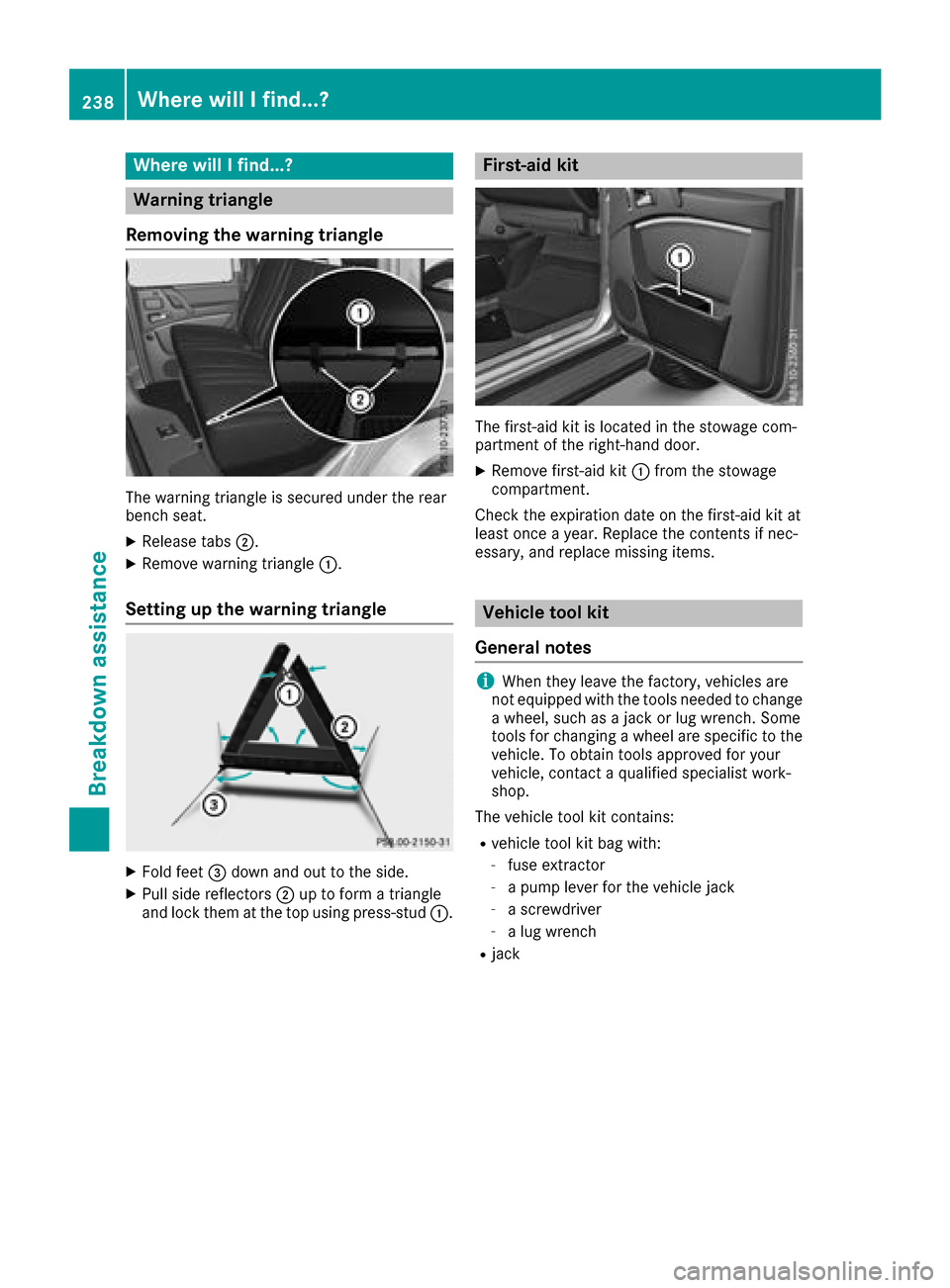
Removing the warning triangle
The warning triangl eissecure dunder the rear
bench seat.
XReleas etabs ;.
XRemove warning triangle :.
Setting up the warning triangle
XFold feet=downa nd out to the side.
XPullside reflectors ;up to form atriangle
and lock them at the top using press-stud :.
First-aid kit
The first-aidkit is located in the stowage com-
partment of the right-hand door.
XRemove first-ai dkit: from the stowage
compartment.
Check the expiration date on the first-ai dkit at
least once ayear. Replace the contents if nec-
essary, and replace missing items.
Vehicle tool kit
General notes
iWhen they leave the factory,v ehicles are
not equipped with the tools neededtoc hange
aw heel, such as ajack or lug wrench. Some
tools for changing awheel are specific to the
vehicle. To obtai ntools approved for your
vehicle, contact aqualified specialist work-
shop.
The vehiclet ool kit contains:
Rvehicletool kit bag with:
-fuse extractor
-apump leverf or the vehiclej ack
-ascrewdriver
-alug wrench
Rjack
238Where will Ifind...?
Breakdown assistance
Page 243 of 286
XClose thedriver' sdoor.
XPlacet hewarning triang leas uitable dist ance
away (Ypage 238). Observ elegal require-
ments.
Battery (vehicle)
Important safety notes
Spe cial tools and expertk nowledg eare required
when working on th ebattery, e.g .removal and
installation. You should therefor ehave all work
involving th ebattery carried out at aqualified
specialist workshop.
GWARNING
Workc arried out incorrect lyon th ebattery
can lead, for example ,toashort circuit and
thus damag ethe veh icle electronics .This can
lead to function restrictionsa pplyingto
safety-relevan tsystems ,e.g th elighting sys-
tem, th eABS (anti-lockb raking system) or the
ESP
®(Electron ic Stabilit yProgram). The oper-
atin gsafety of your veh iclemay berestricted.
You could lose control of th evehicle ,for
example:
Rwhen braking
Rin thee vent of abrupt steering maneuvers
and/or when th evehicle 's speedisn ot
adapted to th eroad conditions
Thereisar iskofana cciden t.
In thee vent of ashort circuit or asimilar inci-
dent, contact aqualified specialist workshop
immediately. Do no tdrivea ny further. You
should have all work involving th ebattery car-
ried out at aqualified specialist workshop.
For further informatio nabout AB Sand ESP
®,
see (Ypage 57) and (Ypage 59).
GWAR NING
Electrostat icbuild-up can lead to th ecreation
of sparks ,whichc ouldignite th ehighly explo-
siveg ases of abattery. Thereisar iskofa n
explos ion.
Before handlin gthe battery, touch th evehicle
body to remove any existing electrostatic
build- up. The highly flammable gas mixtur
eforms when
chargin gthe battery as wellas when jump-start-
ing.
Always mak esure that neither you no rthe bat-
tery is electrostatic allycharge d.Ab uild-up of
electrostatic charge can becaused, for exam-
ple:
Rby wearin gclothing made from synthetic
fibe rs
Rdue to friction between clothing and seats
Rif you push or pull th ebattery across th ecar-
pet or other synthetic materials
Rif you rub th ebattery withac loth
GWARNING
During th echargin gprocess, abattery produ-
ces hydrogen gas. If ashort circuit occur sor
sparks are created, th ehydrogen gas can
ignite .Thereisar iskofane xplosion.
RMakes ure that th epositiv etermi nal of a
connected battery does no tcom eintoc on-
tac twithv ehicle parts.
RNever placem etal objectsortoolson abat-
tery.
RIt is important that you observ ethe descri-
bed order of th ebattery terminal swhen
connecting and disconnecting abattery.
RWhen jump-starting, mak esure that the
battery poles withidentical polarity are
connected.
RIt is particularly important to observ ethe
describe dorder when connecting and dis-
connecting th ejumper cables.
RNever connect or disconnect th ebattery
terminal swhile th eengineisr unning.
GWARNING
Battery acid iscaustic .Thereisar iskofi njury.
Avoid contact withskin, eyes or clothing .Do
no tinhale any battery gases.Don otlean over
th eb attery. Keep ch ildren away from batter-
ies. Wash away battery acid immediately with
plenty of clean wate rand seek medical atten-
tion.
Battery (vehicle)241
Breakdown assistance
Z