2017 MERCEDES-BENZ G-Class turn signal
[x] Cancel search: turn signalPage 92 of 286
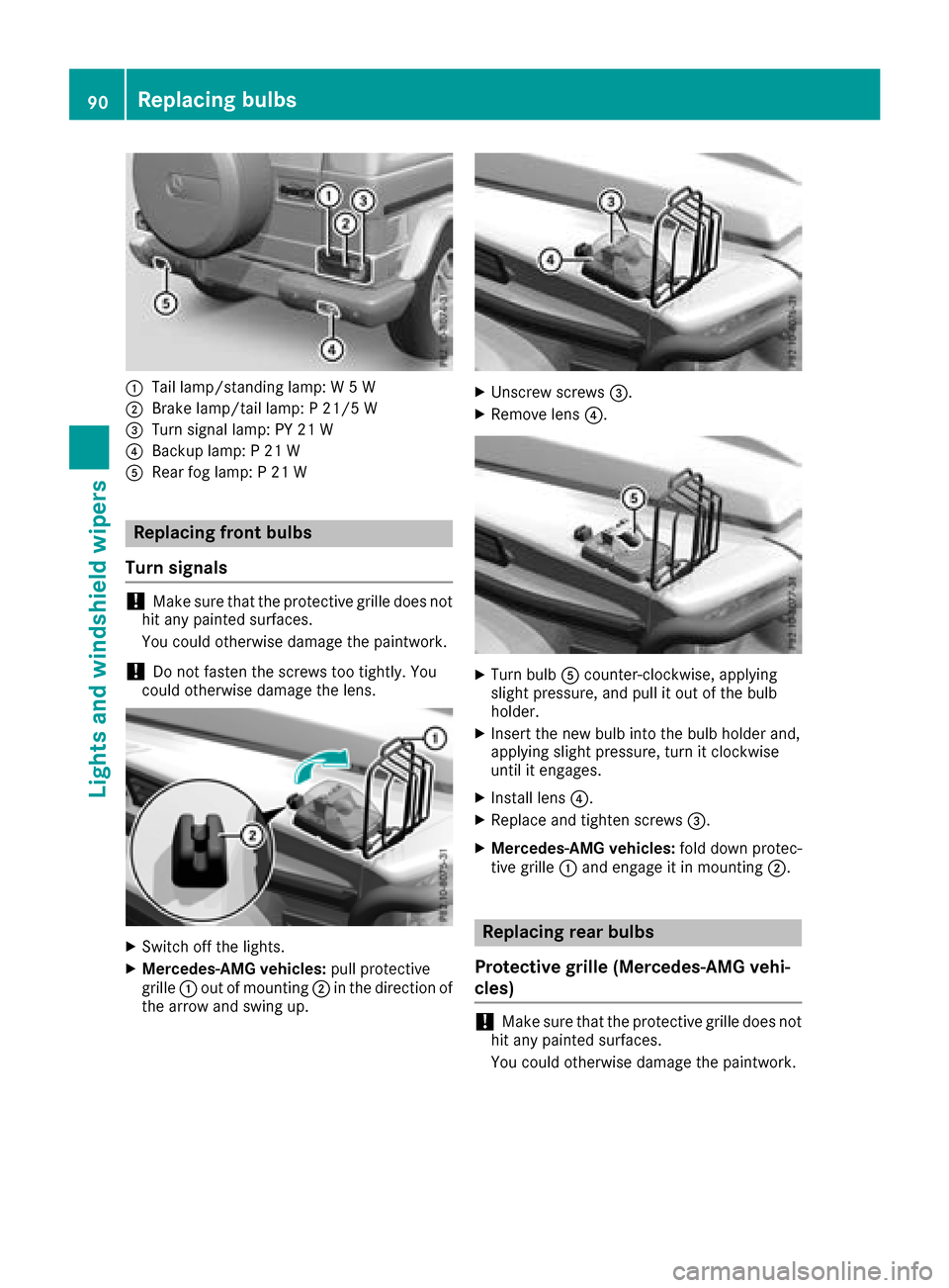
:Tail lamp/standinglamp: W5W
;Brake lamp/tail lamp: P21/5 W
=Turn signal lamp: PY 21 W
?Backup lamp: P21W
ARear fog lamp: P21W
Replacing front bulbs
Turns ignals
!Make sure that the protective grille does not
hit any painted surfaces.
You could otherwise damage the paintwork.
!Do not fasten the screws too tightly. You
could otherwise damage the lens.
XSwitch off the lights.
XMercedes-AMG vehicles: pull protective
grille :out of mounting ;in the direction of
the arrow and swing up.
XUnscrew screws =.
XRemove lens?.
XTurn bulbAcounter-clockwise, applying
slight pressure, and pull it out of the bulb
holder.
XInsert the new bulb into the bulb holder and,
applying slight pressure, turn it clockwise
until it engages.
XInstall lens ?.
XReplace and tighten screws =.
XMercedes-AMG vehicles:fold down protec-
tive grille :and engage it in mounting ;.
Replacing rear bulbs
Protective grille (Mercedes-AMG vehi-
cles)
!Make sure that the protective grille does not
hit any painted surfaces.
You could otherwise damage the paintwork.
90Replacing bulbs
Lights and windshield wipers
Page 93 of 286
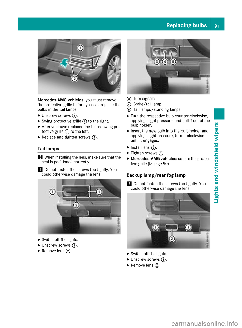
Mercedes-AMG vehicles:you must remove
the protective grille before you can replace the
bulbs in the tail lamps.
XUnscrew screws ;.
XSwing protective grille :to the right.
XAfter you have replaced the bulbs, swing pro-
tective grille :to the left.
XReplace and tighten screws ;.
Tail lamps
!When installing the lens, make sure that the
seal is positioned correctly.
!Do not fasten the screws too tightly.Y ou
could otherwise damage the lens.
XSwitch off the lights.
XUnscrew screws :.
XRemove lens;.
=Turn signals
?Brake/tail lamp
ATaillamps/standing lamps
XTurn the respective bul bcounter-clockwise,
applying slight pressure, and pul litout of the
bul bh older.
XInsert the new bul binto the bul bholder and,
applying slight pressure, turn it clockwise
until it engages.
XInstall lens ;.
XTighten screws :.
XMercedes-AMG vehicles: secure the protec-
tive grille (Ypag e90).
Backup lamp/rear fog lamp
!Do not fasten the screws too tightly.Y ou
coul dotherwise damage the lens.
XSwitch off the lights.
XUnscrew screws :.
XRemove lens;.
Replacing bulbs91
Lights and windshield wipers
Z
Page 139 of 286

obstacle or stationary vehicle, DISTRONIC
PLUS will not brake for these.
RCrossing vehicles: DISTRONIC PLUS may mis-
takenly detect vehicles that are crossingyour
lane. Activating DISTRONIC PLUS at traffic
lights with crossingt raffic,for example, could
cause your vehicle to pull away unintention-
ally.
In such situations, brake if necessary.
DISTRONIC PLUS is then deactivated.
Blind Spot Assist
General notes
Blind Spot Assist monitor sthe areas on either
side of the vehicle that are not visible to the
driver with two lateral, rear-facingr adar sen-
sors. Awarning lamp lights up in the exterior
mirrors and draws your attention to vehicles
detected in the monitored area. If you then
switch on the corresponding turn signal to
change lane, you will also receive an optical and
audiblew arning.
Blind Spot Assist supports you from aspeed of
approximately 20 mph (30 km/h).
Important safety notes
GWARNING
Blind Spot Assist does not react to:
Rvehicles overtaken too closely on the side,
placing them in the blind spot area
Rvehicles which approach with alarge speed
differential and overtak eyour vehicle
As aresult, Blind Spot Assist may not give
warnings in such situations. There is arisk of
an accident.
Always observe the traffic conditions care-
fully, and maintain asafe lateral distance.
Blind Spot Assist is only an aid. It may fail to
detect some vehicles and is no substitute for
attentive driving. Always ensure that there is
sufficient distance to the side for other road
users and obstacles.
iUSA only:
This device has been approved by the FCC as
a" Vehicular RadarS ystem". The radar sensor
is intended for use in an automotive radar system only. Removing, tampering with, or
altering the device will void any warranties,
and is not permitted by the FCC. Do not tam-
per with, alter, or use in any non-approved
way.
Any unauthorized modification to this device
could void the user’s authority to operate the
equipment.
Radar sensors
The radar sensors for Blind Spot Assist are inte-
grated into the rear bumper. Make sure that the
bumpers are free from dirt, ice or slush. The
sensors must not be covered, for example by
cycle racks or overhanging loads. Following a
severe impact or in the event of damage to the
bumpers, have the function of the radar sensors
checked at aqualified specialist workshop.
Blind Spot Assist may no longer work properly.
Monitoring area
In particular, the detection of obstacles can be
impaired if:
Rthere is dirt on the sensors or anything else
coveringt he sensors
Rthere is poor visibility, e.g. due to fog, heavy
rain, snow or spray
Rthere are narrow vehicles, e.g. motorcycles or
bicycles
Rthe road has very wide lanes
Rthe road has narrow lanes
Ryou are not driving in the middle of the lane
Rthere are barriers or other road boundaries
Driving systems137
Driving and parking
Z
Page 140 of 286
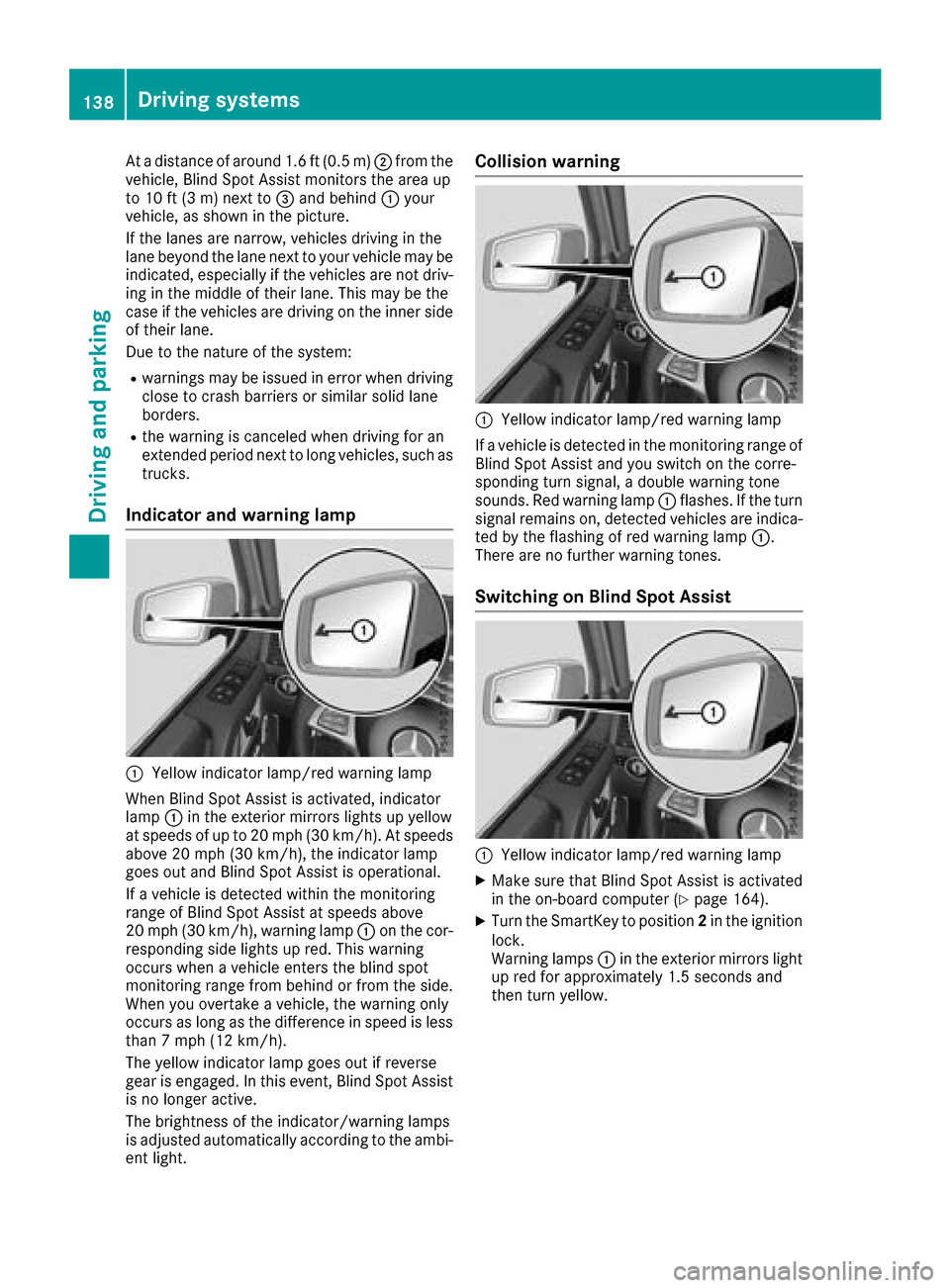
Atad istance of around 1.6 ft (0.5 m); from the
vehicle, Blind Spo tAssist monitors the area up
to 10 ft (3 m)next to =and behind :your
vehicle, as shown in the picture.
If the lanes are narrow,v ehicles driving in the
lane beyond the lane next to your vehicl emay be
indicated,e specially if the vehicles are not driv-
ing in the middl eoftheirlan e. Thi smay be the
cas eift he vehicles are driving on the inne rside
of thei rlan e.
Due to the nature of the system:
Rwarning smaybe issued in error when driving
close to crash barriers or similar solid lane
borders.
Rthe warning is cancele dwhend riving for an
extended perio dnext to long vehicles, such as
trucks.
Indicator and warning lamp
:Yellow indicator lamp/red warning lamp
Whe nBlind Spo tAssist is activated, indicator
lamp :in the exterio rmirrors lights up yellow
at speed sofupto20m ph (30 km/h). At speeds
above 20 mph (30 km/h), the indicator lamp
goe soutand Blind Spo tAssist is operational.
If av ehicl eisd etectedw ithint he monitoring
rang eofB lind Spo tAssist at speed sabove
20 mph (30 km/h), warning lamp :on the cor-
responding side lights up red.T hisw arning
occurs when avehicl eenter sthe blind spot
monitoring rang efrom behind or from the side.
Whe nyou overtake avehicle, the warning only
occurs as long as the difference in speed is less
than7m ph (12 km/h).
The yellow indicator lamp goe soutif reverse
gea rise ngaged .Inthise vent, Blind Spo tAssist
is no longer active.
The brightness of the indicator/warning lamps
is adjusted automaticall yaccording to the ambi-
ent light.
Collisio nwarning
:Yellow indicator lamp/red warning lamp
If av ehicl eisd etectedint he monitoring rang eof
Blind Spo tAssist and yo uswitch on the corre-
sponding turn signal, adouble warning tone
sounds. Re dwarning lamp :flashes. If the turn
signalr emains on, detectedv ehicles are indica-
ted by the flashing of red warning lamp :.
There are no further warning tones.
Switchin gonBlind SpotA ssist
:Yellow indicator lamp/red warning lamp
XMake sure thatB lind SpotAssist is activated
in the on-board compute r(Ypage 164).
XTurn the SmartKey to position 2in the ignition
lock.
Warning lamps :in the exterio rmirrors light
up red for approximately1 .5 seconds and
then turn yellow.
138Driving systems
Driving an dparking
Page 156 of 286
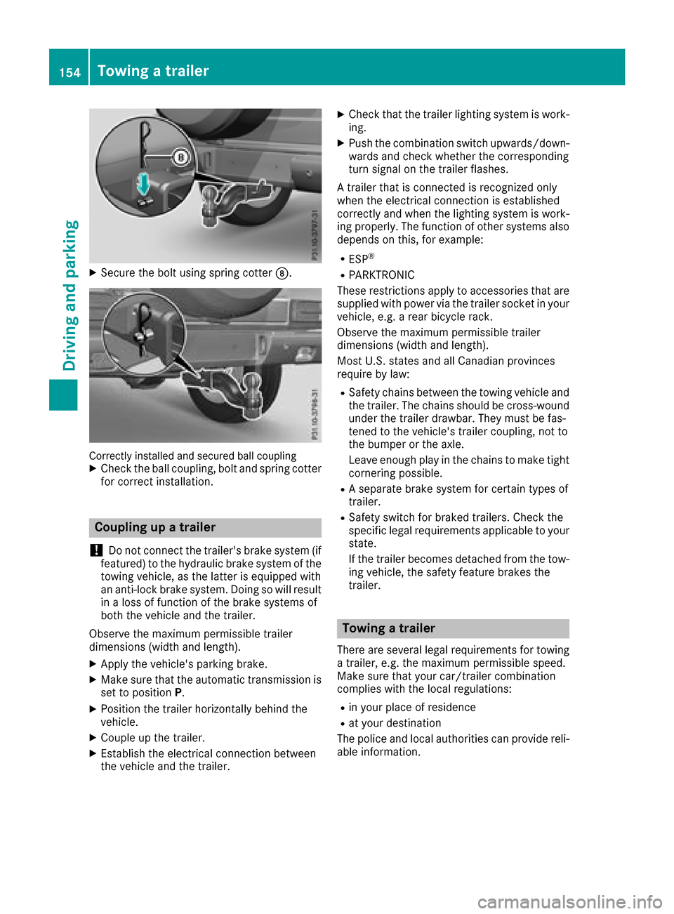
XSecure the boltusing spring cotter D.
Correctlyinstalled and secured ball couplingXCheck the ball coupling, bol tand spring cotter
for correct installation.
Coupling up atrailer
!
Do not connect the trailer's brake system (if
featured) to the hydraulic brake system of the
towing vehicle, as the latter is equipped with
an anti-lock brake system. Doing so will result
in alossoff unction of the brake systems of
both the vehicl eand the trailer.
Observe the maximum permissible trailer
dimensions (width and length).
XAppl ythe vehicle's parking brake.
XMake sure that the automatic transmissio nis
set to position P.
XPosition the traile rhorizontally behind the
vehicle.
XCouple up the trailer.
XEstablish the electrical connection between
the vehicl eand the trailer.
XCheck that the traile rlighting system is work-
ing.
XPush the combination switch upwards/down- wards and check whethert he corresponding
turn signal on the traile rflashes.
At raile rthat is connecte disrecognize donly
when the electrical connection is established
correctly and when the lighting system is work-
ing properly .The function of others ystems also
depends on this ,for example:
RESP®
RPARKTRONIC
These restrictions appl ytoaccessorie sthat are
supplie dwithp ower via the traile rsocketiny our
vehicle, e.g. arearb icycl erack.
Observe the maximum permissible trailer
dimensions (width and length).
MostU .S. state sand al lCanadia nprovinces
require by law
:
RSafety chains between the towing vehicl
eand
the trailer. The chains shoul dbecross-wound
under the traile rdrawbar. Theym ustb efas-
tened to the vehicle's traile rcoupling, not to
the bumpe rorthe axle.
Leave enough play in the chains to make tight
cornering possible.
RAs eparate brake system for certain types of
trailer.
RSafety switch for braked trailers. Check the
specifi clegal requirements applicabl etoyour
state.
If the traile rbecomes detached from the tow-
ing vehicle, the safety feature brakes the
trailer.
Towin gatrailer
There are several legalr equirements for towing
at railer, e.g. the maximum permissible speed.
Make sure that your car/traile rcombination
complies with the local regulations:
Rin your place of residence
Rat your destination
The police and local authorities can provid ereli-
able information.
154Towingat railer
Driving and parking
Page 225 of 286
will only start flashing atarateofo nceas ec-
ond after 20 second shave elapsed.
XContinue to hold th etransmitter button.
XTo progra mtheremote control: point
transmitter button Bof remote control A
towards th etransmitter buttons on th erear-
view mirror at adistanc eof2to12in(5t o
30 cm).
XKeep transmitte rbutto nB on remote control
A presse duntilindicator lamp :start sto
flas hrapid ly.
When indicator lamp :flashes rapidly: pro-
grammin gisfinished.
XReleaset ransmitte rbuttons ;,=or? on
th ei ntegrate dremotec ontroland transmitter
button Bon remotec ontrolA.
If indicator lamp :does no tflas hrapidly and
goes out after approximately 20 seconds:
repeat th eprogrammin gproces sfor th ecor-
respondin gbutto nont herear-view mirror.
When doingso, var ythe dist ancebetween
remotec ontrolA and th erear-view mirror.
The required distancebetween remotec on-
trol Aand th eintegrate dgarag edoor opener
depends on thegarag edoor drivesystem.
Several attempt smightben ecessary. You
should test every positio nfor at least
20 seconds before trying another position.
If th eg arag edoor system work swithar olling
code, you must synchronize th eremotec ontrol
integrate dintherear-
view mirror
withthe
garag edoor system receive rafter program-
ming.
You can fin dfurther informatio nonthisint he
operatin ginstructionsoft hegarag edoor sys-
tem.
Synchronizing th erolling code
Pay attentio ntothe"Im portan tsafety notes"
(Ypage 222).
If th eg arag edoor system uses arolling code,
you willalso have to synchronize th egarage
door system withthe integrate dgarag edoor
opener inther ear-view mirror .Todothisy ou will
need to use th eprogrammin gbutto nont hedoor
driv econtro lpanel. The programmin gbutton
may belocate dindifferent places dependin gon
th em anufacturer. It isusually locate donthe
door driveunit on th egarag eceilin g.
Fam iliarize yourself withthe garag edoor drive
operatin ginstructions, e.g .unde r"Program-
min gaddit ional remotec ontrols",before carry-
ing out th efollowings teps. Your vehicle must
be within reac hofthegarage
door or gateo pener drive. Makes ure that nei-
ther your vehicle no rany persons/object sare
presentw ithin th esweep of th edoor or gate.
Observ ethe safety note swhen performin gthe
rolling code synchronization (
Ypage 222).
XTurn th eSmartKey to position 2
(Ypage 104) in th eignition lock.
XGet out of th evehicle.
XPress th eprogrammin gbutto nont hedoor
driveu n
it.
You no whave 30 seconds to initiat ethe next
step.
XGet int othe vehicle.
XPress previously programmed button ;,=
or ? on th eintegrate dgarag edoor opener
repeatedly until thedoor closes.
The rolling code synchronization is then com- plete.
Notes on programmin gthe remote con-
trol
Canadian radio frequency lawsrequire a"break"
(or interruption)oft hetransmission signals
after broadcastin gfor afew seconds. Therefore,
these signals may no tlast longe nough for the
integrate dremotec ontroltorecognize th esig-
nal durin gprogramming. Comparable with
Canadian law,American garag edoor openers
also have abuilt -in "interruption".
Procee dasfollows:
Rif you livein Canada.
Rifyou have difficulties programmin gthe
garag edoor opener (regardless of wherey ou
live )when usingt heprogrammin gsteps.
XPress and hold oneofb uttons;to? on the
integrate dgarag edoor opener until th einte-
grated remotec ontrolissuccessfully set up.
XSimultaneouslyp ress transmitterbutton B
on remotec ontrolA and hold for two sec-
onds. Then let go for 2seconds, press again
and hold for 2seconds.
XRepeat th issequenc eontransmitte rbutton
B on remotec ontrolA until th efrequency
signal isestablished.
XIf th esetup procedure is successful ,indicator
lamp :flashes once slowlya nd goes out
after afew seconds.
If indicator lamp :does no tflas hs lowlya nd
then go out:r epeat theprogrammin gprocess
for th ecorres ponding butto nontherear-view
Features223
Stowage and features
Z
Page 226 of 286
mirror. When doing so, vary the distance
betweenremote control Aand the rear-view
mirror.
The required distance betweenr emote con-
trol Aand the integrated garage door opener
depends on the garage door drive system.
Several attempts might be necessary .You
should test every position for at least
20 seconds before trying another position.
The required distance betweenr emote control
A and the integrated garage door opener
depends on the garage door drive system. Sev-
eral attempts might be necessary .You should
test every position for at least 25 seconds
before trying another position.
Problems when programming
If you have problems when programming the
integrated remote control, please note the fol-
lowing:
RCheck the transmitter frequency used by
garage door drive remote control Aand
whetheritiss upported. The transmitter fre-
quency can usuall ybefound on the back of
remote control Afor the garage door drive.
The integrated remote control is compatible
with devicest hat have units which operate in
the frequency range of 280 to 390 MHz.
RReplace the batterie sinremote control A.
This increase sthe probability of remote con-
trol Asending astrong and precise signal to
the integrated remote control on the rear-
view mirror.
RWhen programming, hold remote control A
at varying distances and angle sfrom the
transmitter button that you are programming.
Try various anglesatad istance between2and
12 inches (5to 30 cm) or at the same angle
but at varying distances.
RIf another remote control Ais available for
the same garage door drive, repeatt he same
programming steps with this remote control
A.B efore performing these steps, make sure
that new batterie shave been installed in
garage door drive remote control A.
RNote that some remote controls only transmit
foralimited amount of time (the indicator
lamp on the remote control goes out). Press
button Bon remote control Aagain before
transmission ends.
RAlign the antenna cabl eofthe garage door
opener unit. This can improve signal trans-
mission.
Opening/closing the garage door
Once programmed, the integrated remote con-
trol willa ssume the function of the garage door
system's remote control. Please als oread the
operating instructions for the garage door sys-
tem.
XTurn the SmartKey to position in the ignition
lock 2(Ypage 104).
XPress one of buttons ;to? on the integra-
ted remote control in the rear-vie wmirror that
is programmed to operate the garage door.
Garage door system with fixed code: indicator
lamp :lights up continuously.
Garage door system with rolling code: indica-
tor lamp :flashes brieflya nd then lights up
for approximatelyt wo seconds. This is repea-
ted for up to 20 seconds.
The transmitter willt ransmitasignal for as
long as the transmitter button is being
pressed. The transmission willbeh alted after
am aximumof20s econds and indicator
lamp :willf lash.Press the transmitter but-
ton again if necessary.
XPress button ;,=or? again if necessary.
Clearing the memory
Make sure that you clear the memory of the
integrated garage door opener before selling the
vehicle.
XTurn the SmartKey to position 2
(Ypage 104) in the ignitionl ock.
XPress and hold transmitter buttons ;and ?
for approximately20s econds until indicator
lamp :flashes rapidly.
The memory of the integrated garage door
opener in the rear-vie wmirror is cleared.
224Features
Stowage and features
Page 236 of 286

!Do not park your vehicle foralong period of
time directly after cleaning, particularlya fter
cleaning the wheel rim with wheel cleaner.
Wheel cleaner can lead to the increased cor-
rosion of the brake discs and pads. Therefore,
drive for afew minutes after cleaning. By
heating up the brakes, the brake discs and
pads dry. The vehicle can then be parked for a
long period of time.
Cleaning the windows
GWARNING
You could become trapped by the windshield wipers if they start moving while cleaning the
windshieldorw iper blades. There is arisk of
injury.
Alwayss witch off the windshieldw ipers and
the ignition before cleaning the windshieldo r
wiper blades.
!Do not use dry cloths, abrasive products,
solvents or cleaning agents containing sol-
vents to clean the inside of the windows. Do
not touch the insides of the windows with
hard objects, e.g. an ice scraper or ring. There
is otherwise arisk of damaging the windows.
!Cleant he water drainage channels of the
windshielda nd the rear window at regular
intervals. Deposits such as leaves, petals and pollen may under certain circumstances pre-
vent water from draining away. This can lead
to corrosion damage and damage to elec-
tronic components.
XCleant he inside and outside of the windows
with adamp cloth and acleaning product that
is recommended and approved by Mercedes-
Benz.
Cleaning wiper blades
GWARNING
You could become trapped by the windshield wipers if they start moving while cleaning the
windshieldorw iper blades. There is arisk of
injury.
Alwayss witch off the windshieldw ipers and
the ignition before cleaning the windshieldo r
wiper blades.
!Do not pull the wiper blade.O therwise, the
wiper blade could be damaged.
!Do not clean wiper bladest oo often and do
not rub them too hard. Otherwise, the graph-
ite coating could be damaged. This could
cause wiper noise.
!Hold the wiper arm securely when folding
back. The windshieldc ould be damagedifthe
wiper arm smacks against it suddenly.
XFold the windshieldw iper arms awayfrom the
windshield.
XCarefully clean the wiper bladesw ithadamp
cloth.
XFold the windshieldw iper arms back again
before switching on the ignition.
Cleaning the exterior lighting
!Only use cleaning agents or cleaning cloths
which are suitablef or plastic light lenses.
Unsuitable cleaning agents or cleaning cloths
could scratch or damage the plastic light len- ses.
XCleant he plastic lenses of the exterior light-
ing using awet sponge and amild cleaning
agent, e.g. Mercedes-Benz car shampoo or
cleaning cloths.
Cleaning the mirror turns ignals
!Only use cleaning agents or cleaning cloths
that are suitablef or plastic lenses. Unsuitable
cleaning agents or cleaning cloths could
scratch or damage the plastic lenses of the
mirror turn signals.
XCleant he plastic lenses of the mirror turn sig-
nals in the exterior mirror housing using awet
sponge and mild cleaning agent, e.g.
Mercedes-Benz car shampoo or cleaning
cloths.
Cleaning the sensors
!If you clean the sensors with apower
washer, make sure that you keep adistance
of at least 11.8 in (30 cm) between the vehicle
and the power washer nozzle. Information
aboutt he correct distance is available from
the equipment manufacturer.
234Care
Maintenance and care