2017 MERCEDES-BENZ E-CLASS ESTATE ECU
[x] Cancel search: ECUPage 260 of 585
#
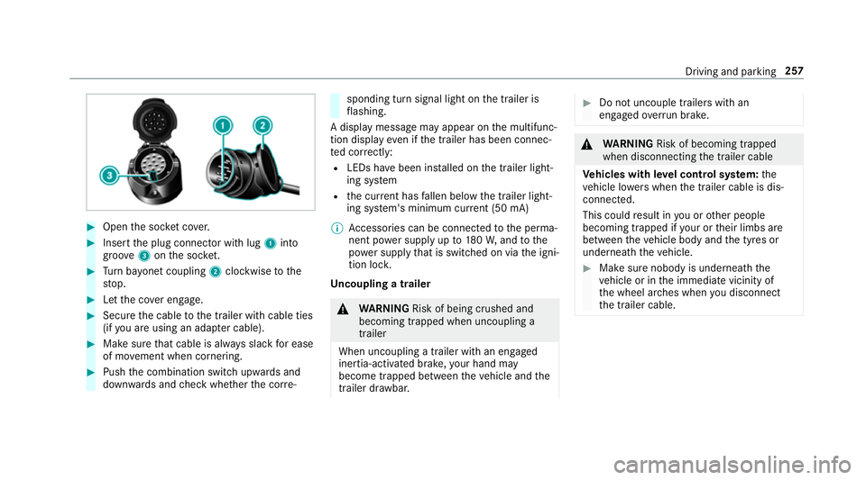
Open thes ocketc ove r. #
Inser tthe plug connector wit hlug 1 into
groo ve3 onthes ocket. #
Turn bayone tc oupling 2clockwise tothe
st op. #
Letthe co vere ngage. #
Secur ethe cable tothet railer wit hcable ties
(if youa reusin gana dapterc able). #
Mak esuret hat cabl eisalway ss lac kfor ease
of mo vement when cornering. #
Push thec ombination switc hupwards and
down wardsa nd checkw hether thec orre‐ sponding tur
nsignal light on thet railer is
fl ashing.
Ad ispla ymessag emayappear on them ultifunc‐
tion displa yevenift he trailer has been connec‐
te dc orrectly:
R LEDs ha vebeen ins talled on thet railer light‐
ing sy stem
R thec urrent ha sfallen belo wthe trailer light‐
ing sy stem's minimum cur rent (50 mA)
% Accessorie scan be connected tothep erma‐
nentp owersupp lyup to180W,a ndtothe
po we rsupp lythat is swit ched on via thei gni‐
tion loc k.
Un coupling atrailer &
WARNING Risk of being crushed and
becoming trapped whe nuncoupling a
trailer
Whe nuncoupling atrailer with an engaged
ine rtia-activated brake, your han dmay
become trapped between thev ehicle and the
traile rdrawbar. #
Do no tuncouple trailer swithan
engaged overrunb rake. &
WARNING Risk of becoming trapped
whe ndisconnecting thet railer cable
Ve hicles with le velc ontrol sy stem: the
ve hicle lo werswhen thet railer cable is dis‐
connected.
This could result in youoro ther people
becoming trapped if your or their limbs are
between thev ehicle body and thet yres or
underneat hthe vehicle. #
Mak esuren obody is underneat hthe
ve hicle or in thei mmediat evicinity of
th ew heel ar ches when youd isconnect
th et railer cable. Driving and parking
257
Page 261 of 585
*
NO
TEDama getother ear bumper from
ins talling adap terc ables or adapte rplugs The
following parts could be damaged when
re tracting theb all nec kfullye lectrically:
R bumper
R adap terc able
R adapte rplug #
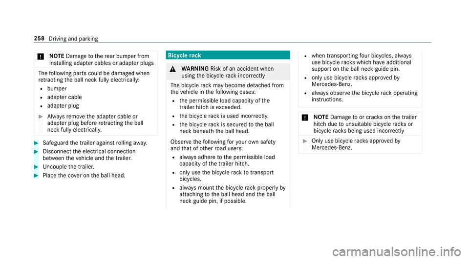
Alw aysr emo vethea dap terc ableor
adapte rplugb efor eretra cting theb all
nec kfullye lectrically. #
Safeguar dthe trailer agains trolling away. #
Disconnect thee lectrical connection
between thev ehicle and thet railer. #
Uncoupl ethe trailer. #
Place thec over on theb all head. Bicycle
rack &
WARNING Risk of an accident when
using theb icycle rack incor rectly
The bicycle rack ma ybecome de tach ed from
th ev ehicle in thef ollowing cases:
R thep ermissible load capacity of the
traile rhitch isexceeded.
R theb icycle rack is used incor rectl y.
R theb icycle rack is secured totheb all
nec kbeneat hthe ball head.
Obser vethef ollowing fory our owns afety
and that of other road users:
R alwaysa dher etot he permissible load
capacity of thet railer hitch.
R onlyusetheb icycle rack totranspo rt
bicycles.
R alwaysm ount theb icycle rack properly by
attachin gtothe ball head and theb all
nec kguide pin, if possible. R
when transporting four bic ycles, alw ays
use bic ycle rack sw hichh ave additional
suppo rton theb all nec kguide pin.
R onlyuse bicycle rack sa ppr ove dby
Mercedes-Benz.
R alwayso bser vetheb icycle rack operating
instructions. *
NO
TEDama getoor crac kson thet railer
hitc hduetounsuitable bic ycle rack sor
bicycle rack sb eing used incor rectly #
Onlyusebicycle rack sa ppr ove dby
Mercedes-Benz. 258
Driving and parking
Page 262 of 585
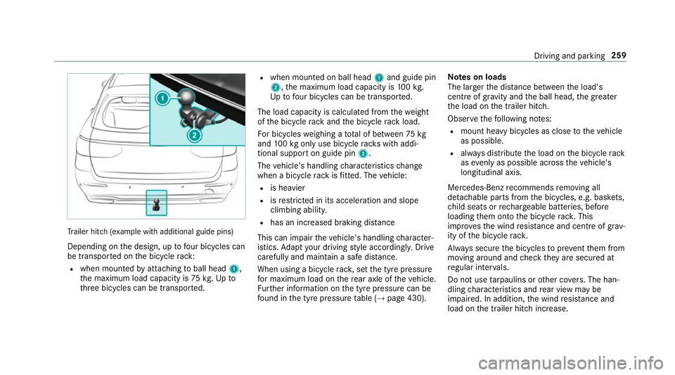
Tr
ailer hit ch(examp le withadditional guide pins)
Depending on thed esign, up tofour bic ycles can
be transpor tedont he bicycle rack:
R when moun tedbya ttachin gtoball head 1,
th em aximum load capacity is 75kg.Upto
th re eb icycles can be transpor ted. R
when mounted on ball head 1and guide pin
2,t he maximum load capacity is 100k g.
Up tofour bic ycles can be transpo rted.
The load capacity is calculated from thew eight
of theb icycle rack and theb icycle rack load.
Fo rb icycles weighin gatotal of between 75kg
and 100k gonlyu se bicycle rack sw itha ddi‐
tional suppor tonguide pin 2.
The vehicle's handling characteristic schange
when abicycle rack isfitted .The vehicle:
R is heavier
R isrestricted in its accele ratio na nd slope
climbing ability.
R hasani ncrease dbraking di stance
This can impair thev ehicle's handling character‐
istics. Adapty our driving stylea ccordingly .Drive
carefully and maintain asafed ista nce.
Whe nusing abicyc le rack ,set thet yrep ressure
fo rm aximu mloadont herear axle of thev ehicle.
Fu rther information on thet yrep ressur ecan be
fo und in thet yrep ressur etable (→ page430). Note
sonl oads
The larger thed ista nce betwee nthe load's
centre of gravity and theb all head, theg reater
th el oad on thet railer hitch.
Obser vethef ollowing no tes:
R mount heavy bicycles as close tothev ehicle
as possible.
R alwaysd istribut ethe load on theb icycle rack
as evenl yasp ossible across thev ehicle's
longitudinal axis.
Mercedes-Ben zrecommends removing all
de tac hable parts from theb icycles, e.g. bask ets,
ch ild seats or rech arge able bat teries, before
loading them ont othe bicycle rack .T his
impr ovesthe wind resis tance and centr eofgrav‐
ity of theb icycle rack.
Alw ayss ecur ethe bicycles topreve ntthem from
moving around and checkt heya resecured at
re gular inter vals.
Do no tuse tarp aulins or other co vers.T he han‐
dling characteristic sand rear vie wmaybe
impaired. In addition ,the wind resis tance and
load on thet railer hitc hincrease. Driving and parking
259
Page 266 of 585
#
Onlyoperat ethis equipment when the
traf fics ituation permits. #
Ifyo uc anno tbes ureoft his,stop the
ve hicle whils tpaying attention toroad
and traf ficc onditions and ope rate the
equipment wit hthe vehicle stationar y. Yo
um usto bse rvet he legal requirements fort he
countr yinwhich youa recur rentl yd riving when
operating theo n-boar dcomputer.
% The on-boar dcomputer displa ysappear on
th em ultifunction displa y(→pag e264). The on-boar
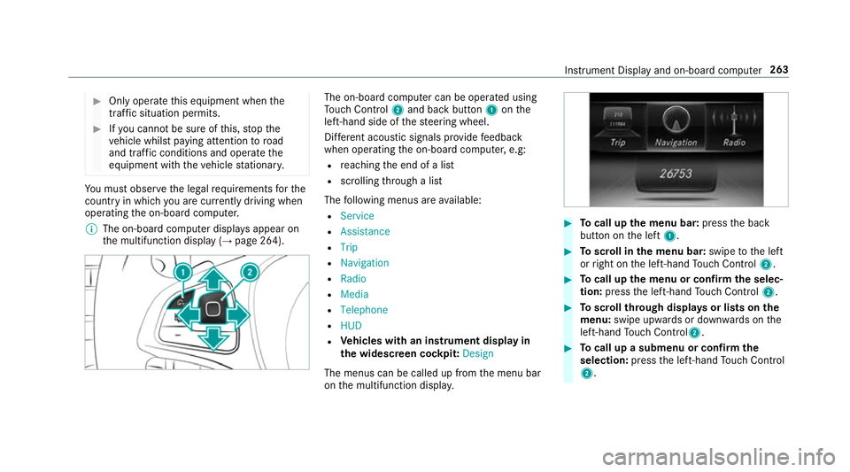
dcomputer can be operated using
To uc hC ontrol 2and bac kbutton 1onthe
left-hand side of thes teering wheel.
Dif fere nt acoustic signals pr ovide feedback
when operating theo n-boar dcomputer ,e.g:
R reachin gthe end of alist
R scrolling thro ugh alist
The following menus ar eavailable:
R Service
R Assistance
R Trip
R Navigation
R Radio
R Media
R Telephone
R HUD
R Vehicles with an instrument displa yin
th ew idescreen cockpit: Design
The menus can be called up from them enu bar
on them ultifunction displa y. #
Tocall up them enu bar: presstheb ack
button on thel eft 1. #
Toscroll in them enu bar: swipetothel eft
or right on thel eft-hand Touc hC ontrol 2. #
Tocall up them enu or confir mthe selec‐
tion: press thel eft-hand Touc hC ontrol 2. #
Toscroll through displa ysor lists on the
menu: swipe upwards or down wardsont he
left-hand Touc hC ontrol2. #
Tocall up asubmen uorconfirmthe
selection: pressthel eft-hand Touc hC ontrol
2. In
stru ment Displa yand on-boar dcomputer 263
Page 270 of 585
When
gliding mode is activ e(→pag e179),
Gliding mode is displayedi nstead of thec ur‐
re nt fue lconsu mption.
Ar ecuperation displa yisalsoavailable for
cer tain engines. If ther eiso nlyas mall
amount of fuel lef tinthe fuel tank ,the dis‐
pla yshows avehicle being refuelled ins tead
of ther ange.
R ECOd ispl ay ( →pag e174 )
R Trip computer Froms tart and Fromr eset
R Digital speedom eter
% Ve
hicles with an Instrument Displa yin
th eW idescreen Cockpit: thed igital speed‐
ome tero nly appear sintheClassic andSport
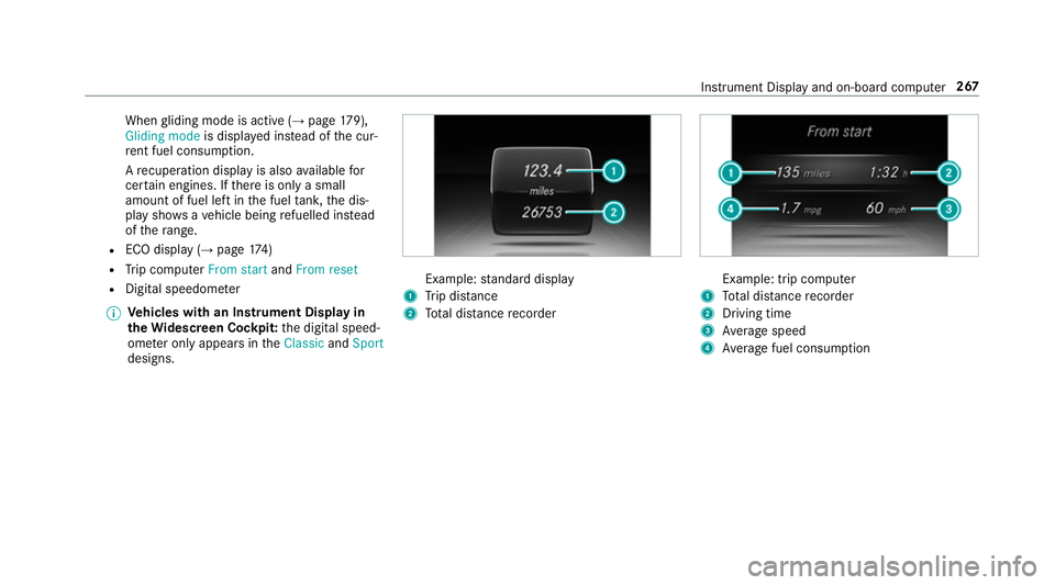
designs. Example:
standar ddisplay
1 Trip dis tance
2 Totald ista nce recorder Example: trip compu
ter
1 Totald ista nce recorder
2 Driving time
3 Averag espeed
4 Averag efuel consum ption Instrumen
tDispla yand on-boar dcomputer 267
Page 301 of 585
Ac
tivating/deactivatin gBluetooth ®
Requ irement:
R Apple CarPlay™ is no tactive.
Multimedia sy stem:
, System .
ö Connectivity #
Activate Oor deacti vate ª Bluetoo th®
.
If Android Autois active, apromp tappear sask‐
ing whe ther Blue tooth®
should be deactivated. #
Select Yes.
Android Autois closed and Blue tooth®
is
deactivated. Wi
-Fi Wi
-Fic on nectio noverview
Yo uc an use Wi-Fi toestablish aconnection with
aW i-Finetwo rkand toaccess theI nterne tor
ot her networ kdevices.
The following connection option sareavailable:
R Wi-Fi connection The
Wi-Fi connectio ntoaWi-Fi-capable
device ,e.g.t he cus tomer's mobil ephone or
at able tPCise stablished.
R multimedia sy stem as aWi-Fihotspot
Using this function ,atable tPCorn otebook
can be connected, fore xamp le.
To establish aconnection ,you can use thef ol‐
lowing me thods:
R WPS PIN
The connection toas ecur eWi-Finetwo rkis
mad eviaaP IN.
R WPS PBC
The connectio ntoasecureWi-Finetwo rkis
mad ebyp ressing abutton (push button).
R security key
The connection toas ecur eWi-Finetwo rkis
mad eviaas ecu rity key. Setting up
Wi-Fi
Requ irement:
R The device tobe connec teds upports one of
th et hree means of connection described
(→ pag e298).
Multimedia sy stem:
, System .
ö Connectivity
Ac tivating/deactivatin gWi-Fi #
Switch Wi-FionO or off ª.
If Wi-Fi is deacti vatedª,communicatio nvia
Wi -Fi toall devices is inter rupte d. This also
means that ac onnectio ntothe HERMES
communication module canno tbeestab‐
lished. Then function ssuchasd ynamic route
guidance wit hLiveT raffic In form ation ar enot
av ailable.
Connecting them ultimedia sy stem wit ha
device via Wi-Fi
Thi sfunction is available if aHERME Scommuni‐
cation modul eisnotins talled. 298
Multimedia sy stem
Page 302 of 585
The type of connection es
tablished mus tbe
selected on them ultimedia sy stem and on the
device tobe connec ted.
% The connection procedur emaydiffer
dependin gonthe device. Followt he instruc‐
tions that ar eshown in thed ispla y.Fu rther
information (see them anufacturer's operat‐
ing instructions). #
Select Internet settings . #
Select Search for Wi-Fi networks.
Using aWPS PIN: #
Highlight aWi-Finetwo rkinthel ist. #
Select ¥Connec tusing WPS PIN input.
The multimedia sy stem generates an eight-
digi tPIN. #
Enter this PIN on thed evice tobe connec ted. #
Confir mthe entr y.
Using abutton:
Re quirements:
R This function is onl yavailable in aWi-Fifre‐
qu ency of 2.4 GHz. #
Highlight aWi-Finetwo rkinthel ist. #
Select ¥Connec tvia WPS PBC. #
Select "Connec tvia WPS PBC" in theo ptions
on thed evice tobe connec ted. #
Press theW PS button on thed evice tobe
connec ted. #
Select Continue inthem ultimedia sy stem.
Using asecurity key: #
Highlight aWi-Finetwo rkinthel ist. #
Select ¥Connec tusing securit ykey. #
Have thes ecurity keyd ispla yedont he device
to be connec ted( see them anufacturer's
operating instructions). #
Ente rthis security keyo nthe multimedia sys‐
te m. #
Confir mthe entr ywith¡.
% All devices suppor tasecurity keyasa
mean sofconnection.
Device ha salread ybeen connec ted: #
Toautomaticall yconnect: highlight aWi-Fi
networ kinthe list. #
Activate ¥ Connect automatically O. #
Toconnect: highlightaWi-Finetwo rkinthe
list. #
Select ¥Connect.
The connection is es tablished again. These
function sarepossible when thed evice has
already been connected totheW i-Finetwo rk.
Setting up awifih otspot
Multimedia sy stem:
, System .
ö Connectivity
Configuring them ultimedia sy stem as awifi
hotsp ot
The type of connection es tablished depends on
th ed evice tobe connec ted. The function must
be suppor tedbyt he multimedia sy stem and by
th ed evice tobe connec ted. The type of connec‐
tion es tablished mus tbeselected on them ulti‐
media sy stem and on thed evice tobe connec‐
te d. #
Select Set up hotspot. #
Highlight Connectdevice to vehicle hotspot. Multimedia sy
stem 299
Page 303 of 585
Genera
tingaW PS PIN #
Select ¥Connect using WPS PIN genera-
tion. #
Enter theP IN shown in them ultimedia sys‐
te md ispla yont he device tobe connec ted
and con firm.
Connecting usin gaWPS PIN #
Select ¥Connect usin gWPS PIN input. #
Select Enter WPS PIN. #
Entert he PIN that is shown on thee xternal
device's displa yonthe multimedia sy stem. #
Select Continue.
Connecting using abutton
Re quirements:
R This function is onl yavailable in aWi-Fifre‐
qu ency of 2.4 GHz. #
Select ¥Connec tvia WPS PBC. #
Press theW PS button on thed evice tobe
connec tedors electConnect. #
Select Continue inthem ultimedia sy stem. Connecting using
asecurity key #
Select Connect device to vehicl ehotspot .
As ecu rity keyisd isplayed. #
Select thev ehicle from thed evice tobe con‐
nec ted. The vehicle is displa yedw itht he
SSID MB Hotspot XXXXX. #
Enter thes ecurity keyw hichiss hown in the
multimedia sy stem displa yonthe device to
be connec ted. #
Confir mthe entr y.
Connecting usin gNFC #
Select Establish aconnectio nvia NFC. #
Activat eNFC on them obile device (see the
manufacturer's operating instructions). #
Bring them obile device int othe NFC area of
th ev ehicle (→ page340). #
Select Done.
The mobile device is no wconnected tothe
multimedia sy stem hotspo tvia NFC.
To generat eanewsecurity key: #
Select Set up hotspot . #
Select Generate security key .
Ac onnection will be es tablished wit hthe
newly created security key. #
Tosave asecurity key:select Save.
When anew security keyiss aved, all existing
Wi -Fi connections ar ethen disconnected. If
th eW i-Ficonnections ar ebeing re-es tab‐
lished, then ew security keym ustbee ntered. Managin
gCOMAND Touc hd evices Re
quirements:
R The COMAND Touc ha pp is ins talled on the
ex tern al devic e(e.g. table tors martphone).
R Wi-Fi is acti vated( →pag e298) and them ul‐
timedia sy stem is confi gured asawifih ot‐
spo t(→ pag e299).
Multimedia sy stem:
, System .
COMAND Touch
Connecting anew device #
Select Authorise anew device. #
Select Connec tnew device. 300
Multimedia sy stem