2017 FORD SUPER DUTY change wheel
[x] Cancel search: change wheelPage 275 of 636
Step 5: Enter Measurements Using the
Information Display
Using the recorded measurements, enter
the required data into the system. Follow
the on screen prompts to enter each of the
measurements taken in step 4. Use the
up/down arrows to increase or decrease
the numbers as needed. Press OK to
confirm each measurement. The screen
prompts you to add the next
measurement. Once you add your last
measurement, the information display
shows you all of your entered
measurements. You can choose to confirm
or change the measurements.
Step 6: Confirming the Sticker Location
Check the Rear View Camera display to
see if the sticker is identified by the system
and marked with a red circle.
Confirm that the red circle is correctly
located over the sticker image in the
display. The on screen prompt will ask you
to confirm this.
Note:
If the system cannot locate the
sticker try cleaning the camera lens, and
also make sure the sticker is within the zone
as indicated in step 3.
The information display shows a
confirmation message when you
successfully confirm the target.
Calibrating the System
To complete setup, drive your vehicle
straight forward between 4 mph (6 km/h)
and 24 mph (39 km/h) as directed by the
information display.
Note: Keep the steering wheel straight
during the calibration process. If the steering
wheel is in a turned position, then the
calibration pauses. The information display
prompts you to drive straight forward to
complete the calibration. The information display shows a message
during calibration and after calibration is
complete
Note:
For best results, we do not
recommend that you calibrate the system
at night.
Using Trailer Reverse Guidance
1. Shift into reverse (R) if you are not already in reverse. Press the rear
camera button to expand the menu.
2. Press the trailer icon .
3. Select your trailer on your information display.
4. While in TRG mode, you can see the camera view on the side where your
trailer is moving, or both sides when
the trailer is straight behind you. When
the views change with the trailer
direction, it's called Auto Mode. For
example, If you turn the trailer to the
right, then you see the right side of your
vehicle and trailer. You can switch this
view manually at any time by using the
arrow keys. To return to Auto Mode,
press the Auto button.
Note: Auto Mode is your default setting.
Use the view that helps you the most while
backing up your vehicle and trailer. Normal rear view camera view.
Use this feature when you want
to see your trailer hitch or what
is directly behind your vehicle. Straight back-up mode. Use this
feature when you want to keep
your trailer completely in line
with your truck. In this mode, a steering
wheel graphic shows you which way to turn
your steering wheel to keep your trailer
straight.
272
Super Duty (TFE) Canada/United States of America, enUSA, First Printing TowingE224483 E224484
Page 276 of 636
Note:
It may be helpful to shift your vehicle
into drive (D), pull forward and straighten
out the vehicle and trailer before engaging
Straight Backup Mode.
Left and right arrows let you see other
views regardless of your trailer angle. Use
them to switch views manually.
Note: If you're using a Fifth Wheel or
Gooseneck trailer, or you haven't set up the
Trailer Reverse Guidance System yet, Auto
View is not available.
To change your view, use the arrows. You
can see the following views:
• Full driver
• Partial driver
• 50/50
• Partial passenger
• Full passenger Zoom. Use this feature to zoom
in on any view.
Return. Ths feature takes you
back to the 360-degree camera
system and out of the Trailer
Reverse Guidance feature. Auto. Ths feature returns you to
automatic view mode.
In addition to multiple view options, your
touchscreen adds some features to give
you more information.
After using the set up for a conventional
trailer, for example, the display always
shows you a small, top-view
representation of your truck and trailer.
This representation shows two,
different-colored lines: A black line shows
you where your trailer is in relation to your
vehicle. A white line gives you a projection
of where your trailer will go based on your
current steering wheel position Note:
When you move the steering wheel,
the white line indicates where the trailer will
go based on your steering wheel input.
When you turn your steering wheel to the
left, the trailer moves to the right; when you
turn your steering wheel to the right, the
trailer moves to the left.
When you turn the wheel, the small
representation shows you two zones to
warn you of a possible jackknife condition.
The view shows you your truck and trailer
position and provides visual feedback to
help you avoid jackknifing entirely.
The yellow zone warns you of a potential
jackknife position. When you enter into this
zone, it's best to put your vehicle back into
drive (D) and pull forward. Moving forward
helps put the truck and trailer back into an
in-line position.
The RED zone indicates that you need to
put the truck into drive (D) and pull
forward immediately.
Troubleshooting
Note: The system requires a clear view of
the sticker placed on the trailer. You must
keep the camera lens and sticker clean for
the system to operate correctly.
Setup
The system is designed to be used with a
wide variety of trailers. However there are
some trailers that do not have a proper
surface and location to mount the sticker.
These trailers are not supported. Attempts
to place the sticker on a surface that does
not meet the sticker placement
requirement listed in Step 3 of the setup
instruction or entering inaccurate
measurements to proceed through setup
can result in improper system function.
273
Super Duty (TFE) Canada/United States of America, enUSA, First Printing TowingE224485 E224487 E224486
Page 279 of 636
Sticker lost:
•
Check for the following if you receive
the lost sticker message while using
the system.
•Stop your vehicle as soon as the
message displays.
• Make sure the sticker is visible in
the rear view camera image.
• Clean the sticker and camera to
make sure they are unobstructed.
• Remove any items that may be
blocking the view of the sticker.
Depending on your trailer
configuration and any equipment
mounted to your trailer it is possible
for the sticker to be blocked from
view of the camera as it rotates on
the hitch ball but not be blocked
during setup. Remove the
obstruction if possible. It will be necessary to remove the sticker
from it’
s current location if the
obstruction cannot be cleared and
place a new sticker that will be
visible to the camera in all positions
of the trailer behind your vehicle.
• You can change your sticker
location by going into the trailer
menu, selecting trailer options,
selecting change trailer settings
and then selecting the change
sticker option. The previous sticker
must be removed. ONLY ONE
STICKER SHOULD BE PLACED
ON THE TRAILER FOR CORRECT
SYSTEM FUNCTION.
• The camera system uses the
entered measurements to help
locate the sticker. Inaccurate
measurements will reduce the
system ’s ability to locate the
sticker. Check the measurements
entered into the system are correct.
Refer to the step 4 of Trailer
Reverse Guidance setup for
instructions on measurements.
• You can change your measurement
by going into the trailer menu,
selecting trailer options, selecting
change trailer setting and then
selecting the change sticker option.
Disregard the prompt to remove
this sticker and continue to the next
step if you only plan to update the
measurements for the current
sticker location.
System will not backup straight:
• Factors such as the drawbar
connection to the hitch receiver, road
camber, road grade and compliance in
the trailer suspension can influence
how straight the system is able to back
your trailer when the wheel is not
turned. You can compensate for the
trailer drifting to the right or left by
276
Super Duty (TFE) Canada/United States of America, enUSA, First Printing Towing
Page 280 of 636
slowly turning the wheel until the trailer
is following your desired path and then
holding the wheel in that position. If
you would like to recalibrate the
system for straight backing, you can do
so with the following procedure.
•
Go into the trailer menu, select
trailer options, select change trailer
setting and then select the change
sticker option. Your saved
measurements will be displayed.
Do not change them but continue
to confirm measurements. Once
you confirm the measurements, the
system will then prompt you to
perform the calibration procedure.
Note: The system is designed to be used
with the same trailer connection every time
the trailer is chosen from the selection
menu. Using a different drawbar or a
different pin hole (on drawbars with more
than one) when connecting the drawbar to
your vehicle will affect the trailer
measurements. Take the measurements
again and update if required.
TRAILER SWAY CONTROL (If
Equipped) WARNING
Turning off trailer sway control
increases the risk of loss of vehicle
control, serious injury or death. Ford
does not recommend disabling this feature
except in situations where speed reduction
may be detrimental (such as hill climbing),
the driver has significant trailer towing
experience, and can control trailer sway
and maintain safe operation. Note:
This feature does not prevent trailer
sway, but reduces it once it begins.
Note: This feature cannot stop all trailers
from swaying. Note:
In some cases, if vehicle speed is too
high, the system may activate multiple
times, gradually reducing vehicle speed.
This feature applies your vehicle brakes at
individual wheels and, if necessary, reduces
engine power. If the trailer begins to sway,
the stability control light flashes and the
message
TRAILER SWAY REDUCE
SPEED appears in the information display.
The first thing to do is slow your vehicle
down, then pull safely to the side of the
road and check for proper tongue load and
trailer load distribution. See
Load
Carrying (page 261).
RECOMMENDED TOWING
WEIGHTS WARNING
You must use the heavy-duty
drawbar pin supplied with
your vehicle when using the
heavy-duty hitch. Failure to follow
this instruction could result in the
loss of control of your vehicle,
personal injury or death. Note:
Vehicles with a heavy-duty
hitch must use the drawbar pin
stamped 21,000 LBS. You can
obtain a replacement drawbar pin
at your Ford dealer.
Note: Make sure to take into
consideration trailer frontal area.
Do not exceed 60 feet 2
(5.6
meters 2
) trailer frontal area for
conventional trailers. Do not
exceed 75 feet 2
(6.9 meters 2
) trailer
frontal area for 5th wheel and
gooseneck trailers.
277
Super Duty (TFE) Canada/United States of America, enUSA, First Printing Towing
Page 285 of 636
When attaching the trailer wiring connector
to your vehicle, only use a proper fitting
connector that works with the vehicle and
trailer functions. Some seven-position
connectors may have the SAE J2863 logo,
which confirms that it is the proper wiring
connector and works correctly with your
vehicle.
Function
Color
Left turn signal and stop lamp
Yellow
Ground (-)
White
Electric brakes
Blue
Right turn signal and stop
lamp
Green
Battery (+)
Orange
Running lights
Brown
Reverse lights
Grey
Dynamic Hitching Using the Rear
View Camera System
Note: Active guidelines and fixed guidelines
are only available when the transmission is
in reverse (R).
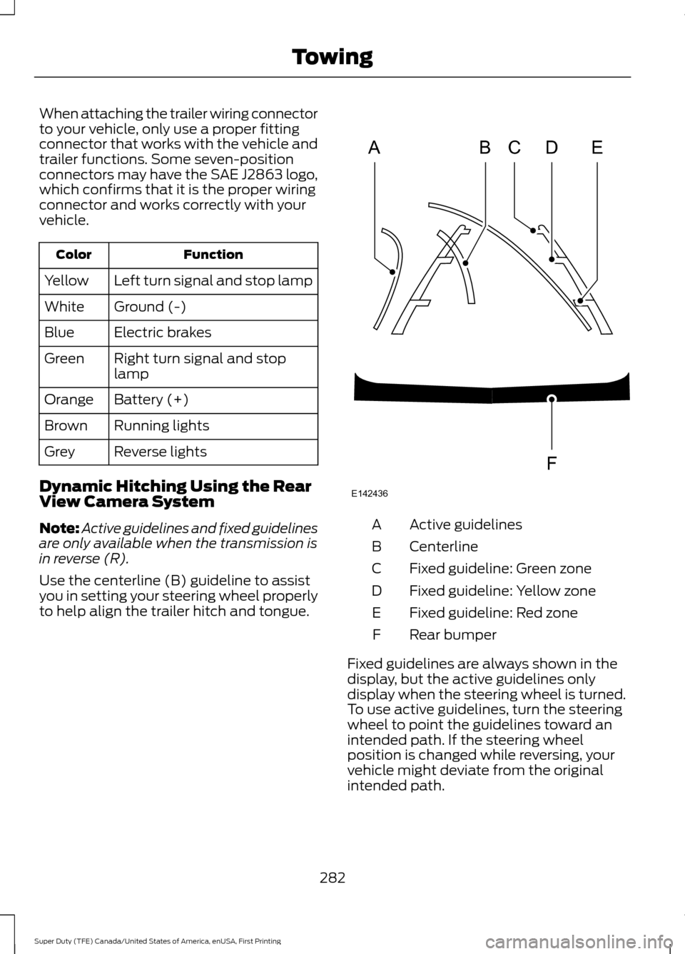
Use the centerline (B) guideline to assist
you in setting your steering wheel properly
to help align the trailer hitch and tongue. Active guidelines
A
Centerline
B
Fixed guideline: Green zone
C
Fixed guideline: Yellow zone
D
Fixed guideline: Red zone
E
Rear bumper
F
Fixed guidelines are always shown in the
display, but the active guidelines only
display when the steering wheel is turned.
To use active guidelines, turn the steering
wheel to point the guidelines toward an
intended path. If the steering wheel
position is changed while reversing, your
vehicle might deviate from the original
intended path.
282
Super Duty (TFE) Canada/United States of America, enUSA, First Printing TowingABCD
F
E
E142436
Page 289 of 636
Procedure for Setting Trailer Brake
Controller Effort
Choose either the electric option for trailers
with electromagnetic drum brakes, or the
electric over hydraulic option for trailers
with these brake systems.
Trailer Brake Effort Setting
The trailer brake controller allows the user
to customize how aggressively the trailer
brakes engage. The default value is the low
setting and is the recommended setting
for most trailers. If your trailer's brakes
require more initial voltage, or if you prefer
more aggressive trailer braking, then select
either the medium or the high setting.
Procedure for Setting Trailer Brake
Controller Mode
Choose the low, medium or high setting
for the required initial trailer brake output.
Procedure for Adjusting Gain
Note:
Only perform this procedure in a
traffic-free environment at speeds of
approximately 20-25 mph (30-40 km/h).
The gain setting adjusts the trailer brake
controller for the specific towing condition.
You should change the setting as towing
conditions change. Changes to towing
conditions include trailer load, vehicle load,
road conditions and weather.
The gain should be set to provide the
maximum trailer braking assistance while
making sure the trailer wheels do not lock
when using the brakes. Locked trailer
wheels may lead to trailer instability.
1. Make sure the trailer brakes are in good
working condition, functioning normally
and properly adjusted. See your trailer
dealer if necessary.
2. Hook up the trailer and make the electrical connections according to the
trailer manufacturer's instructions. 3. When you plug in a trailer with electric
or electric-over-hydraulic brakes, a
confirmation message appears in the
information display.
4. Use the gain adjustment (+ and -) buttons to increase or decrease the
gain setting to the desired starting
point. A gain setting of 6.0 is a good
starting point for heavier loads.
5. In a traffic-free environment, tow the trailer on a dry, level surface at a speed
of 20-25 mph (30-40 km/h) and
squeeze the manual control lever
completely.
6. If the trailer wheels lock up, indicated by squealing tires, reduce the gain
setting. If the trailer wheels turn freely,
increase the gain setting. Repeat Steps
5 and 6 until the gain setting is at a
point just below trailer wheel lock-up.
If towing a heavier trailer, trailer wheel
lock-up may not be attainable even
with the maximum gain setting of 10.
Information Display Warning Messages
Note: An authorized dealer can diagnose
the trailer brake controller to determine
exactly which trailer fault has occurred.
However, your Ford warranty does not cover
this diagnosis if the fault is with the trailer.
TRAILER BRAKE MODULE FAULT
Displays in response to faults sensed by
the trailer brake controller, accompanied
by a single tone. If this message appears,
contact an authorized dealer as soon as
possible for diagnosis and repair. The
controller may still function, but with
degraded performance.
WIRING FAULT ON TRAILER
Displays when there is a short circuit on
the electric brake output wire.
286
Super Duty (TFE) Canada/United States of America, enUSA, First Printing Towing
Page 290 of 636
If this message displays, with no trailer
connected, the problem is with your vehicle
wiring or trailer brake controller. Contact
an authorized dealer.
If the message only displays with a trailer
connected, the problem is with the trailer
wiring. Consult your trailer dealer for
assistance. This can be a short to ground
(such as a chaffed wire), short to voltage
(such as a pulled pin on trailer emergency
breakaway battery) or the trailer brakes
may be drawing too much current.
Points to Remember
Note:
Do not attempt removal of the trailer
brake controller without consulting the
Workshop Manual. Damage to the unit may
result.
• Adjust gain setting before using the
trailer brake controller.
• Adjust gain setting, using the procedure
above, whenever road, weather, trailer
or vehicle loading conditions change
from when the gain was initially set.
• Only use the manual control lever for
proper adjustment of the gain during
trailer setup. Misuse, such as
application during trailer sway, could
cause instability of trailer or tow
vehicle.
• Avoid towing in adverse weather
conditions. The trailer brake controller
does not provide anti-lock control of
the trailer wheels. Trailer wheels can
lock up on slippery surfaces, resulting
in reduced stability of trailer and tow
vehicle.
• The trailer brake controller is equipped
with a feature that reduces output at
vehicle speeds below 11 mph (18 km/h)
so trailer and vehicle braking is not jerky
or harsh. This feature is only active
when applying the brakes using your
vehicle's brake pedal, not the
controller. •
The controller interacts with the brake
control system and powertrain control
system of your vehicle to provide the
best performance on different road
conditions.
• Your vehicle's brake system and the
trailer brake system work
independently of each other. Changing
the gain setting on the controller does
not affect the operation of your
vehicle's brakes.
• When you switch the engine off, the
controller output is disabled and the
display and module shut down.
Trailer Lamps WARNING
Never connect any trailer lamp wiring
to the vehicle's tail lamp wiring; this
may damage the electrical system
resulting in fire. Contact your authorized
dealer as soon as possible for assistance
in proper trailer tow wiring installation.
Additional electrical equipment may be
required. Trailer lamps are required on most towed
vehicles. Make sure all running lights, brake
lights, turn signals and hazard lights are
working.
Before Towing a Trailer
Practice turning, stopping and backing up
to get the feel of your vehicle-trailer
combination before starting on a trip.
When turning, make wider turns so the
trailer wheels clear curbs and other
obstacles.
287
Super Duty (TFE) Canada/United States of America, enUSA, First Printing Towing
Page 292 of 636
When backing down a ramp during boat
launching or retrieval:
•
Do not allow the static water level to
rise above the bottom edge of the rear
bumper.
• Do not allow waves to break higher
than 6 in (15 cm) above the bottom
edge of the rear bumper.
Exceeding these limits may allow water to
enter vehicle components:
• Causing internal damage to the
components.
• Affecting driveability, emissions, and
reliability.
Replace the rear axle lubricant anytime
the rear axle has been submerged in water.
Water may have contaminated the rear
axle lubricant, which is not normally
checked or changed unless a leak is
suspected or other axle repair is required.
TOWING THE VEHICLE ON
FOUR WHEELS
Emergency Towing
If your vehicle becomes inoperable
(without access to wheel dollies,
car-hauling trailer, or flatbed transport
vehicle), it can be flat-towed (all wheels
on the ground, regardless of the powertrain
and transmission configuration) under the
following conditions:
• Your vehicle is facing forward for
towing in a forward direction.
• Place the transmission in position
N. If
you cannot move the transmission into
N
, you may need to override it. See
Transmission (page 205).
• Maximum speed is 35 mph (56 km/h).
• Maximum distance is
50 mi (80 km). WARNING
If your vehicle has a steering wheel
lock make sure the ignition is in the
accessory or on position when being
towed. Recreational Towing
Note:
Put your climate control system in
recirculated air mode to prevent exhaust
fumes from entering your vehicle. See
Climate Control
(page 145).
Follow these guidelines if you have a need
for recreational towing, such as towing
your vehicle behind a motorhome. We
designed these guidelines to prevent
damage to your transmission.
Two-wheel Drive Vehicles and
Four-wheel Drive Vehicles Equipped
with an Electronic-shift Transfer Case
Do not tow your vehicle with any wheels
on the ground, as vehicle or transmission
damage may occur. It is recommended to
tow your vehicle with all four (4) wheels
off the ground, such as when using a
car-hauling trailer. Otherwise, you cannot
tow your vehicle.
Four-wheel Drive Vehicles Equipped
with a Manual-shift Transfer Case
1. Put the transmission in position
N.
2. Put the transfer case in position
N.
3. Put the hub locks in the FREE position.
Always make sure that both hub locks
are set to the same position.
289
Super Duty (TFE) Canada/United States of America, enUSA, First Printing Towing