2017 DODGE GRAND CARAVAN warning light
[x] Cancel search: warning lightPage 105 of 530
CAUTION!
To avoid damage to the mirror during cleaning, never
spray any cleaning solution directly onto the mirror.
Apply the solution onto a clean cloth and wipe the
mirror clean.
Outside Mirrors
To receive maximum benefit, adjust the outside mirror(s) to
center on the adjacent lane of traffic with a slight overlap of
the view obtained on the inside mirror.
WARNING!
Vehicles and other objects seen in an outside convex
mirror will look smaller and farther away than they
really are. Relying too much on side convex mirrors
could cause you to collide with another vehicle or other
object. Use your inside mirror when judging the size or
distance of a vehicle seen in a side convex mirror.
Driver’s Outside Automatic Dimming Mirror — If
Equipped
The driver ’s outside mirror will automatically adjust for
glare from vehicles behind you. This feature is controlled
by the inside automatic dimming mirror and will automati-
cally adjust for headlight glare when the inside mirror
adjusts.
Outside Mirrors Folding Feature
All outside mirrors are hinged and may be moved either
forward or rearward to resist damage. The hinges have
three detent positions:
•Full forward position
• Full rearward position
• Normal position
3
UNDERSTANDING THE FEATURES OF YOUR VEHICLE 103
Page 108 of 530

BLIND SPOT MONITORING (BSM) — IF EQUIPPED
The Blind Spot Monitoring (BSM) system uses two radar-
based sensors, located inside the rear bumper fascia, to
detect highway licensable vehicles (automobiles, trucks,
motorcycles, etc.) that enter the blind spot zones from the
rear/front/side of the vehicle.
When the vehicle is started, the BSM warning light will
momentarily illuminate in both outside rear view mirrors
to let the driver know that the system is operational.The BSM system sensors operate when the vehicle is in any
forward gear or REVERSE and enters stand-by mode when
the vehicle is in PARK.
The BSM detection zone covers approximately one lane
width on both sides of the vehicle 12 ft (3.8 m). The zone
length starts at the outside rear view mirror and extends
approximately 10 ft (3 m) beyond the rear bumper of the
vehicle. The BSM system monitors the detection zones on
both sides of the vehicle when the vehicle speed reaches
approximately 6 mph (10 km/h) or higher and will alert
the driver of vehicles in these areas.
Rear Detection Zones
BSM Warning Light
106 UNDERSTANDING THE FEATURES OF YOUR VEHICLE
Page 109 of 530
NOTE:
•The BSM system does NOT alert the driver about
rapidly approaching vehicles that are outside the detec-
tion zones.
• The BSM system detection zone DOES NOT change if
your vehicle is towing a trailer. Therefore, visually verify
the adjacent lane is clear for both your vehicle and trailer
before making a lane change. If the trailer or other object
(i.e., bicycle, sports equipment) extends beyond the side
of your vehicle, this may result in the BSM warning light
remaining illuminated the entire time the vehicle is in a
forward gear.
The area on the rear fascia where the radar sensors are
located must remain free of snow, ice, and dirt/road
contamination so that the BSM system can function prop-
erly. Do not block the area of the rear fascia where the radar
sensors are located with foreign objects (bumper stickers,
bicycle racks, etc.).
The BSM system notifies the driver of objects in the
detection zones by illuminating the BSM warning light
located in the outside mirrors in addition to sounding an
audible (chime) alert and reducing the radio volume. Refer
to “Modes Of Operation” for further information. The BSM system monitors the detection zone from three
different entry points (side, rear, front) while driving to see
if an alert is necessary. The BSM system will issue an alert
during these types of zone entries.
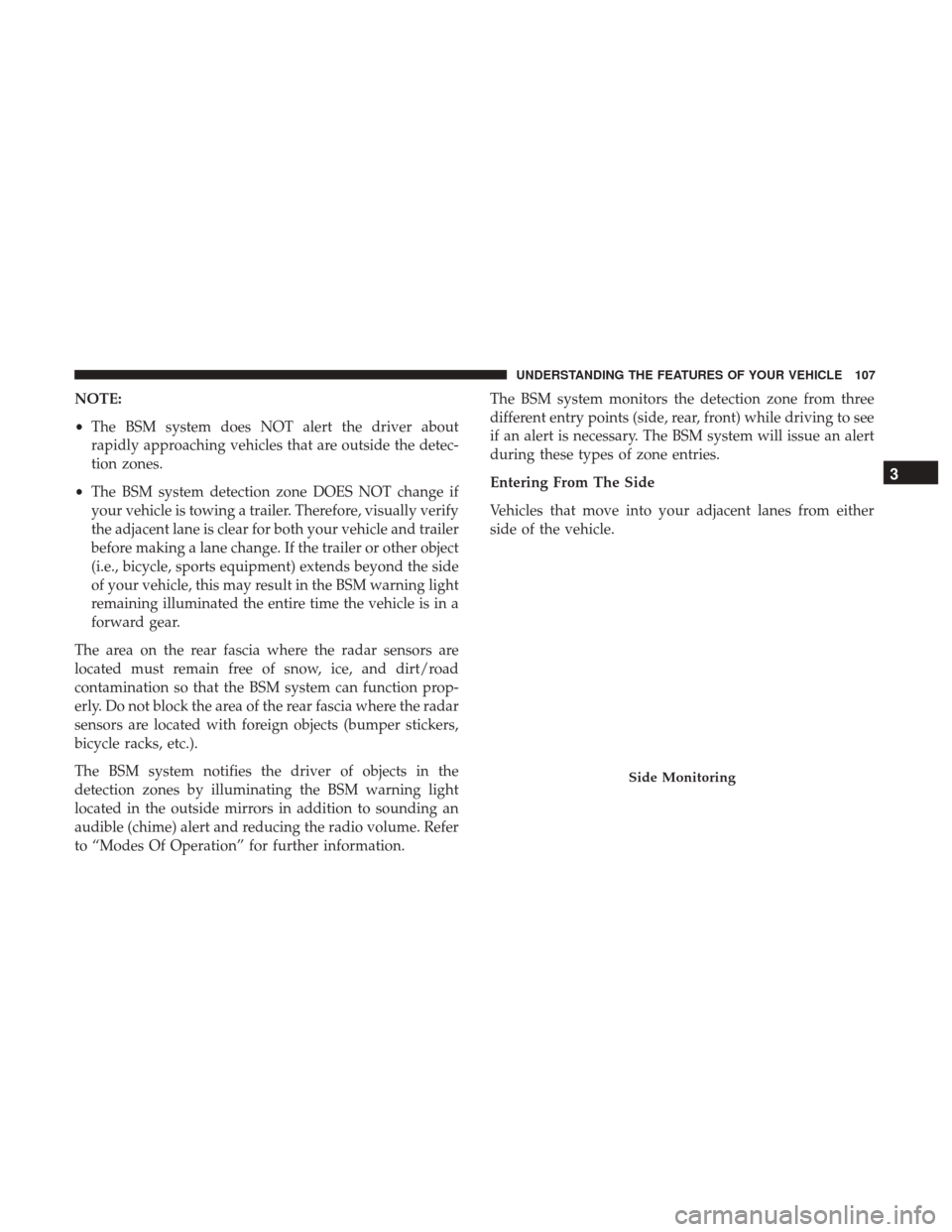
Entering From The Side
Vehicles that move into your adjacent lanes from either
side of the vehicle.
Side Monitoring
3
UNDERSTANDING THE FEATURES OF YOUR VEHICLE 107
Page 110 of 530
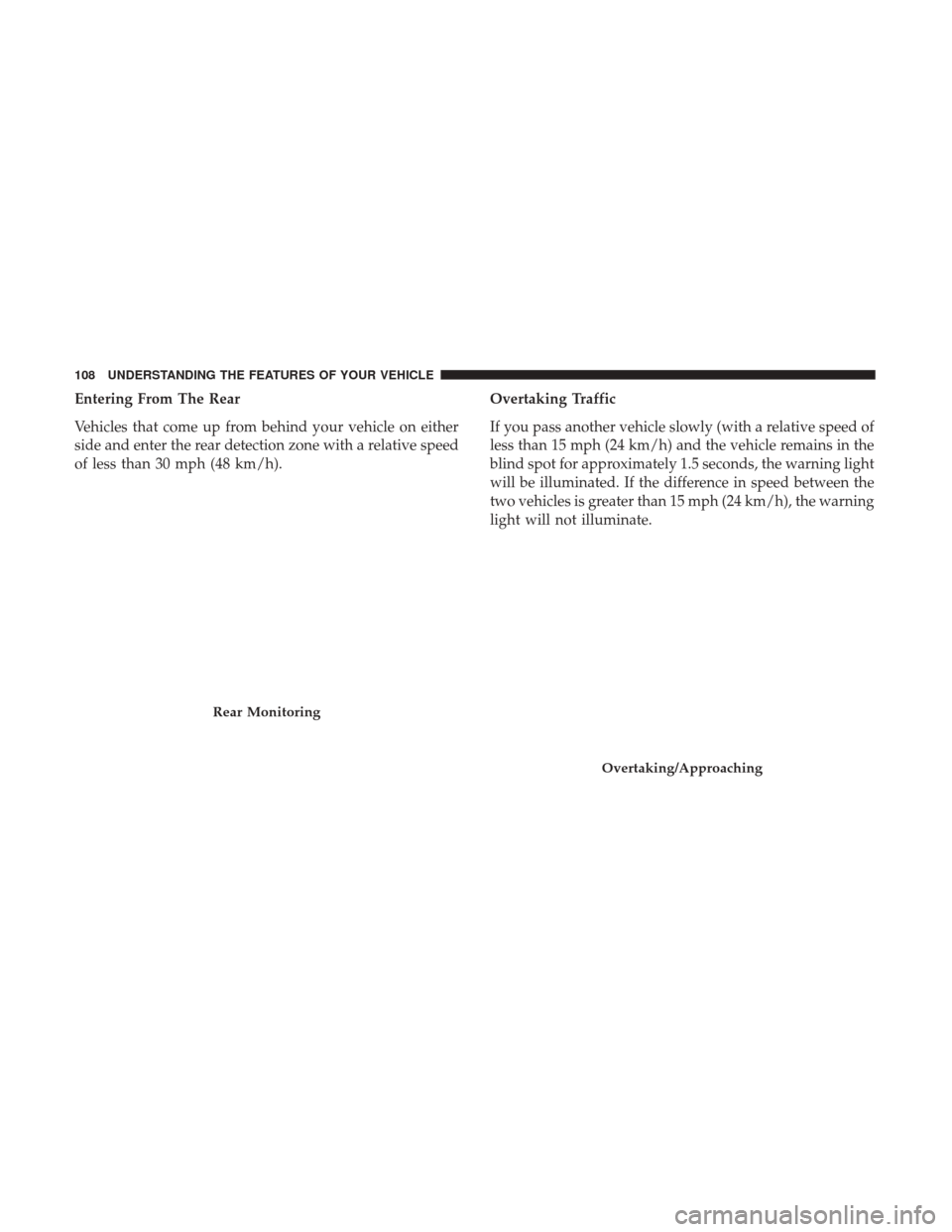
Entering From The Rear
Vehicles that come up from behind your vehicle on either
side and enter the rear detection zone with a relative speed
of less than 30 mph (48 km/h).Overtaking Traffic
If you pass another vehicle slowly (with a relative speed of
less than 15 mph (24 km/h) and the vehicle remains in the
blind spot for approximately 1.5 seconds, the warning light
will be illuminated. If the difference in speed between the
two vehicles is greater than 15 mph (24 km/h), the warning
light will not illuminate.
Rear Monitoring
Overtaking/Approaching
108 UNDERSTANDING THE FEATURES OF YOUR VEHICLE
Page 113 of 530
RCP monitors the rear detection zones on both sides of the
vehicle, for objects that are moving toward the side of the
vehicle with a minimum speed of approximately 3 mph
(5 km/h), to objects moving a maximum of approximately
20 mph (32 km/h), such as in parking lot situations.
NOTE:In a parking lot situation, oncoming vehicles can be
obscured by vehicles parked on either side. If the sensors
are blocked by other structures or vehicles, the system will
not be able to alert the driver.
When RCP is on and the vehicle is in REVERSE, the driver
is alerted using both the visual and audible alarms, includ-
ing reducing the radio volume.
WARNING!
RCP is not a back up aid system. It is intended to be
used to help a driver detect an oncoming vehicle in a
parking lot situation. Drivers must be careful when
backing up, even when using RCP. Always check
carefully behind your vehicle, look behind you, and be
sure to check for pedestrians, animals, other vehicles,
obstructions, and blind spots before backing up. Fail-
ure to do so can result in serious injury or death.
Modes Of Operation
Modes Of Operation With Instrument Cluster Display
Three selectable modes of operation are available in the
Instrument Cluster Display. Refer to “Instrument Cluster
Display/Personal Settings (Customer-Programmable Fea-
tures)” in “Understanding Your Instrument Panel” for
further information.
Blind Spot Alert Lights Only
When operating in Blind Spot Alert mode, the BSM system
will provide a visual alert in the appropriate side view
mirror based on a detected object. However, when the
system is operating in RCP, the system will respond with
both visual and audible alerts when a detected object is
present. Whenever an audible alert is requested, the radio
volume is reduced.
Blind Spot Alert Lights/Chime
When operating in Blind Spot Alert Lights/Chime mode,
the BSM system will provide a visual alert in the appro-
priate side view mirror based on a detected object. If the
turn signal is then activated, and it corresponds to an alert
present on that side of the vehicle, an audible chime will
also be sounded. Whenever a turn signal and detected
object are present on the same side at the same time, both
3
UNDERSTANDING THE FEATURES OF YOUR VEHICLE 111
Page 125 of 530
If the phone is not reachable and the Uconnect Phone is
operational, you may reach the emergency number as
follows:
•Push the Phone
button to begin.
•After the “Ready” prompt and the following beep, say
“Emergency” and the Uconnect Phone will instruct the
paired mobile phone to call the emergency number. This
feature is supported in the U.S., Canada, and Mexico.
NOTE:
• The emergency number dialed is based on the country
where the vehicle is purchased (911 for the U.S. and
Canada and 060 for Mexico). The number dialed may
not be applicable with the available mobile service and
area.
• If supported, this number may be programmable on
some systems. To do this, push the Phone
button and
say “Setup,” followed by “Emergency.”
• The Uconnect Phone does slightly lower your chances of
successfully making a phone call as to that for the
mobile phone directly.
WARNING!
To use your Uconnect Phone System in an emergency,
your mobile phone must be:
•Turned on.
• Paired to the Uconnect System.
• Have network coverage.
Roadside Assistance/Towing Assistance
If you need roadside assistance:
• Push the Phone
button to begin.
•After the “Ready” prompt and the following beep, say
“Towing Assistance.”
NOTE: You should program the desired Towing Assistance
phone number using the Voice Command system. To do
this, push the Phone
button and say “Setup,” fol-
lowed by “Towing Assistance.” When prompted say
1-800-521-2779 for U.S./Canada, say 55-14-3454 for
Mexico City and 1-800-712-3040 for outside Mexico City
in Mexico. 3
UNDERSTANDING THE FEATURES OF YOUR VEHICLE 123
Page 148 of 530
You can choose from HI, LO or OFF heat settings. Amber
indicator lights in each switch indicate the level of heat in
use. Two indicator lights will illuminate for HI, one for LO
and none for OFF.Push the switch once to select HI-level heating.
Push the switch a second time to select LO-level
heating. Push the switch a third time to shut the
heating elements OFF.
NOTE: Once a heat setting is selected, heat will be felt
within two to five minutes.
When the HI-level setting is selected, the heater will
provide a boosted heat level during the initial stages of
operation. Then, the heat output will drop to the normal
HI-level. If the HI-level setting is selected, the system will
automatically switch to LO-level after approximately 60
minutes of continuous operation. At that time, the display
will change from HI to LO, indicating the change. The
LO-level setting will turn OFF automatically after approxi-
mately 45 minutes.
Manual Front/Second Row Seat Adjuster
Both front seats are adjustable forward or rearward. The
manual seat adjustment handle is located under the seat
cushion at the front edge of each seat. While sitting in the seat, pull up on the handle and slide the
seat forward or rearward. Release the bar once you have
reached the desired position. Then, using body pressure,
move forward and rearward on the seat to be sure that the
seat adjusters have latched.
WARNING!
•
Adjusting a seat while driving may be dangerous.
Moving a seat while driving could result in loss of
(Continued)
Manual Seat Adjuster
146 UNDERSTANDING THE FEATURES OF YOUR VEHICLE
Page 149 of 530
WARNING!(Continued)
control which could cause a collision and serious
injury or death.
• Seats should be adjusted before fastening the seat
belts and while the vehicle is parked. Serious injury
or death could result from a poorly adjusted seat belt.
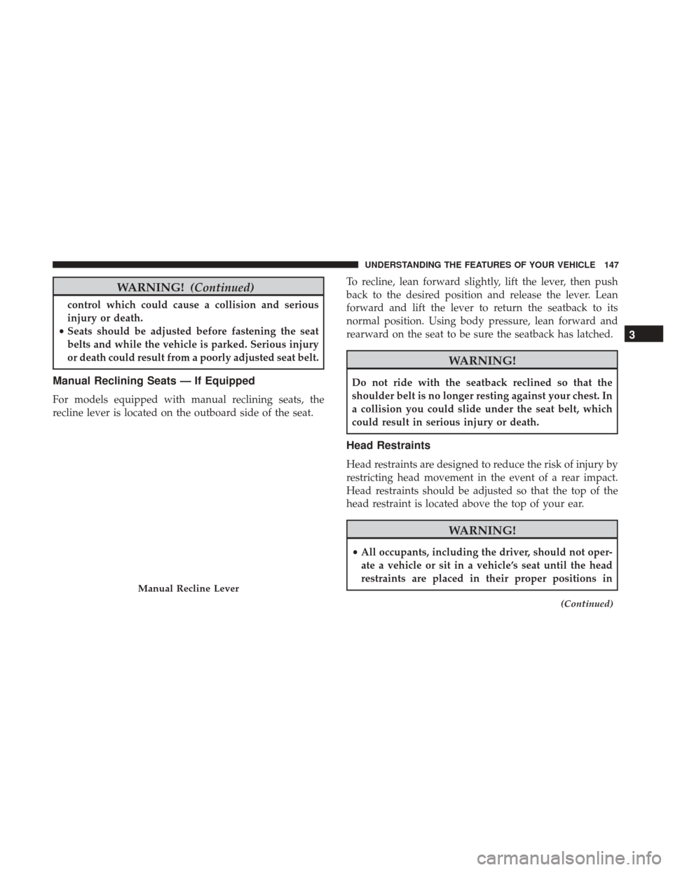
Manual Reclining Seats — If Equipped
For models equipped with manual reclining seats, the
recline lever is located on the outboard side of the seat. To recline, lean forward slightly, lift the lever, then push
back to the desired position and release the lever. Lean
forward and lift the lever to return the seatback to its
normal position. Using body pressure, lean forward and
rearward on the seat to be sure the seatback has latched.
WARNING!
Do not ride with the seatback reclined so that the
shoulder belt is no longer resting against your chest. In
a collision you could slide under the seat belt, which
could result in serious injury or death.
Head Restraints
Head restraints are designed to reduce the risk of injury by
restricting head movement in the event of a rear impact.
Head restraints should be adjusted so that the top of the
head restraint is located above the top of your ear.
WARNING!
•
All occupants, including the driver, should not oper-
ate a vehicle or sit in a vehicle’s seat until the head
restraints are placed in their proper positions in
(Continued)
Manual Recline Lever
3
UNDERSTANDING THE FEATURES OF YOUR VEHICLE 147