Page 57 of 268
INTERNAL
EQUIPMENT
Glove Compartment
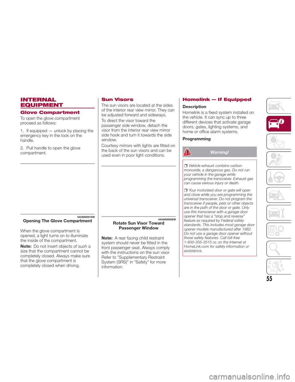
To open the glove compartment
proceed as follows:
1. If equipped — unlock by placing the
emergency key in the lock on the
handle.
2. Pull handle to open the glove
compartment.
When the glove compartment is
opened, a light turns on to illuminate
the inside of the compartment.
Note:Do not insert objects of such a
size that the compartment cannot be
completely closed. Always make sure
that the glove compartment is
completely closed when driving.
Sun Visors
The sun visors are located at the sides
of the interior rear view mirror. They can
be adjusted forward and sideways.
To direct the visor toward the
passenger side window, detach the
visor from the interior rear view mirror
sidehookandturnittowardstheside
window.
Courtesy mirrors with lights are fitted on
the back of the sun visors and can be
used even in poor light conditions.
Note: A rear facing child restraint
system should never be fitted in the
front passenger seat. Always comply
with the instructions on the sun visor.
Refer to "Supplementary Restraint
System (SRS)" in "Safety" for more
information.
Homelink — If Equipped
Description
Homelink is a fixed system installed on
the vehicle. It can sync up to three
different devices that activate garage
doors, gates, lighting systems, and
home or office alarm systems.
Programming
Warning!
Vehicle exhaust contains carbon
monoxide, a dangerous gas. Do not run
your vehicle in the garage while
programming the transceiver. Exhaust gas
can cause serious injury or death.
Your motorized door or gate will open
and close while you are programming the
universal transceiver. Do not program the
transceiver if people, pets or other objects
are in the path of the door or gate. Only
use this transceiver with a garage door
opener that has a “stop and reverse”
feature as required by Federal safety
standards. This includes most garage door
opener models manufactured after 1982.
Do not use a garage door opener without
these safety features. Call toll-free
1-800-355-3515 or, on the Internet at
HomeLink.com for safety information or
assistance.
04246S0001EMOpening The Glove Compartment04246S0002EMRotate Sun Visor Toward Passenger Window
55
Page 63 of 268
GETTING TO KNOW YOUR INSTRUMENT PANEL
This section gives you all the
information you need to understand
and use the instrument panel correctly.INSTRUMENT PANEL FEATURES . .62
INSTRUMENT CLUSTER
DISPLAY..................64
WARNING LIGHTS AND
MESSAGES ON THE INSTRUMENT
PANEL....................70
ONBOARD DIAGNOSTIC
SYSTEM ..................94
61
Page 67 of 268
Reconfigurable
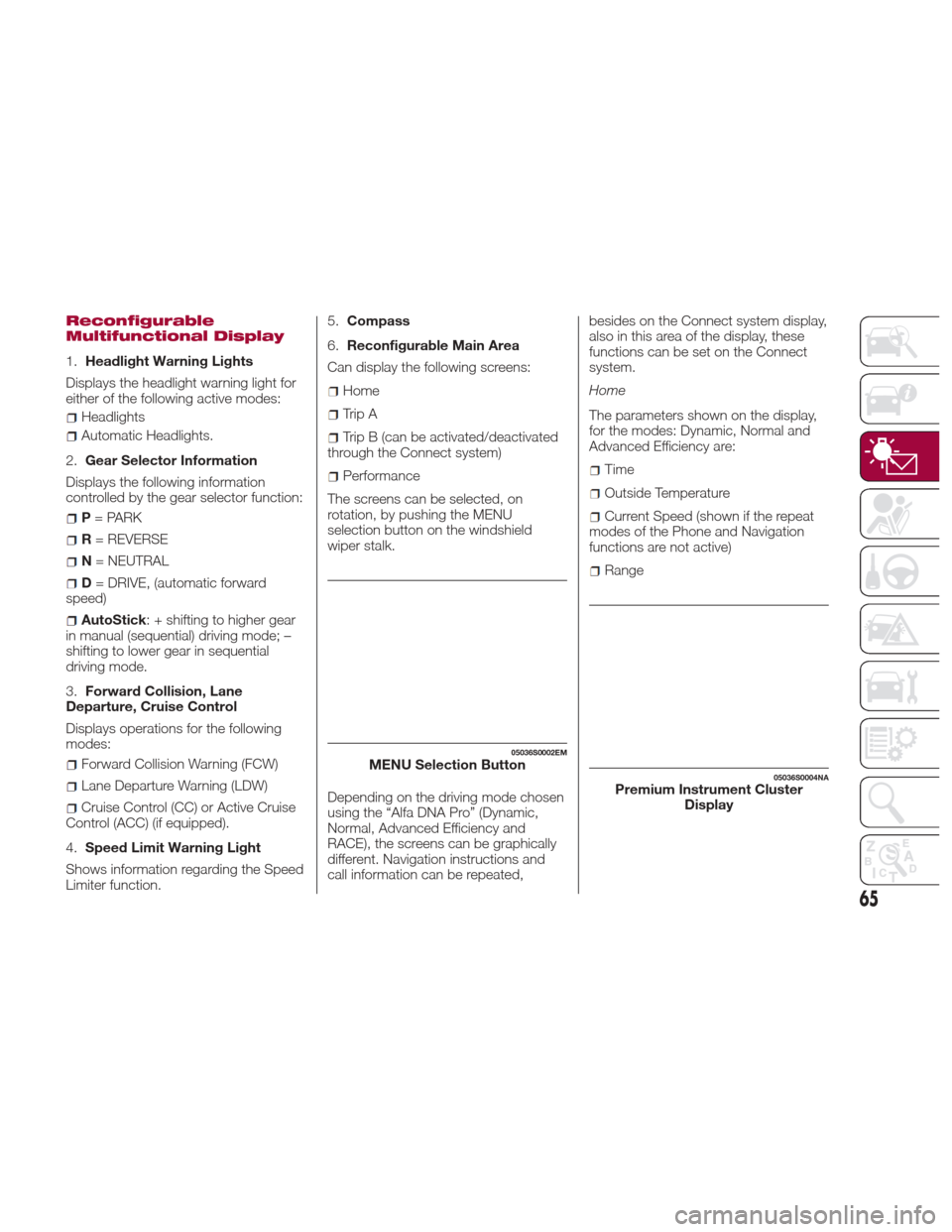
Multifunctional Display
1.Headlight Warning Lights
Displays the headlight warning light for
either of the following active modes:
Headlights
Automatic Headlights.
2. Gear Selector Information
Displays the following information
controlled by the gear selector function:
P = PARK
R = REVERSE
N = NEUTRAL
D= DRIVE, (automatic forward
speed)
AutoStick : + shifting to higher gear
in manual (sequential) driving mode; –
shifting to lower gear in sequential
driving mode.
3. Forward Collision, Lane
Departure, Cruise Control
Displays operations for the following
modes:
Forward Collision Warning (FCW)
Lane Departure Warning (LDW)
Cruise Control (CC) or Active Cruise
Control (ACC) (if equipped).
4. Speed Limit Warning Light
Shows information regarding the Speed
Limiter function. 5.
Compass
6. Reconfigurable Main Area
Can display the following screens:
Home
Trip A
Trip B (can be activated/deactivated
through the Connect system)
Performance
The screens can be selected, on
rotation, by pushing the MENU
selection button on the windshield
wiper stalk.
Depending on the driving mode chosen
using the “Alfa DNA Pro” (Dynamic,
Normal, Advanced Efficiency and
RACE), the screens can be graphically
different. Navigation instructions and
call information can be repeated, besides on the Connect system display,
also in this area of the display, these
functions can be set on the Connect
system.
Home
The parameters shown on the display,
for the modes: Dynamic, Normal and
Advanced Efficiency are:Time
Outside Temperature
Current Speed (shown if the repeat
modes of the Phone and Navigation
functions are not active)
Range
05036S0002EMMENU Selection Button05036S0004NAPremium Instrument Cluster Display
65
Page 69 of 268
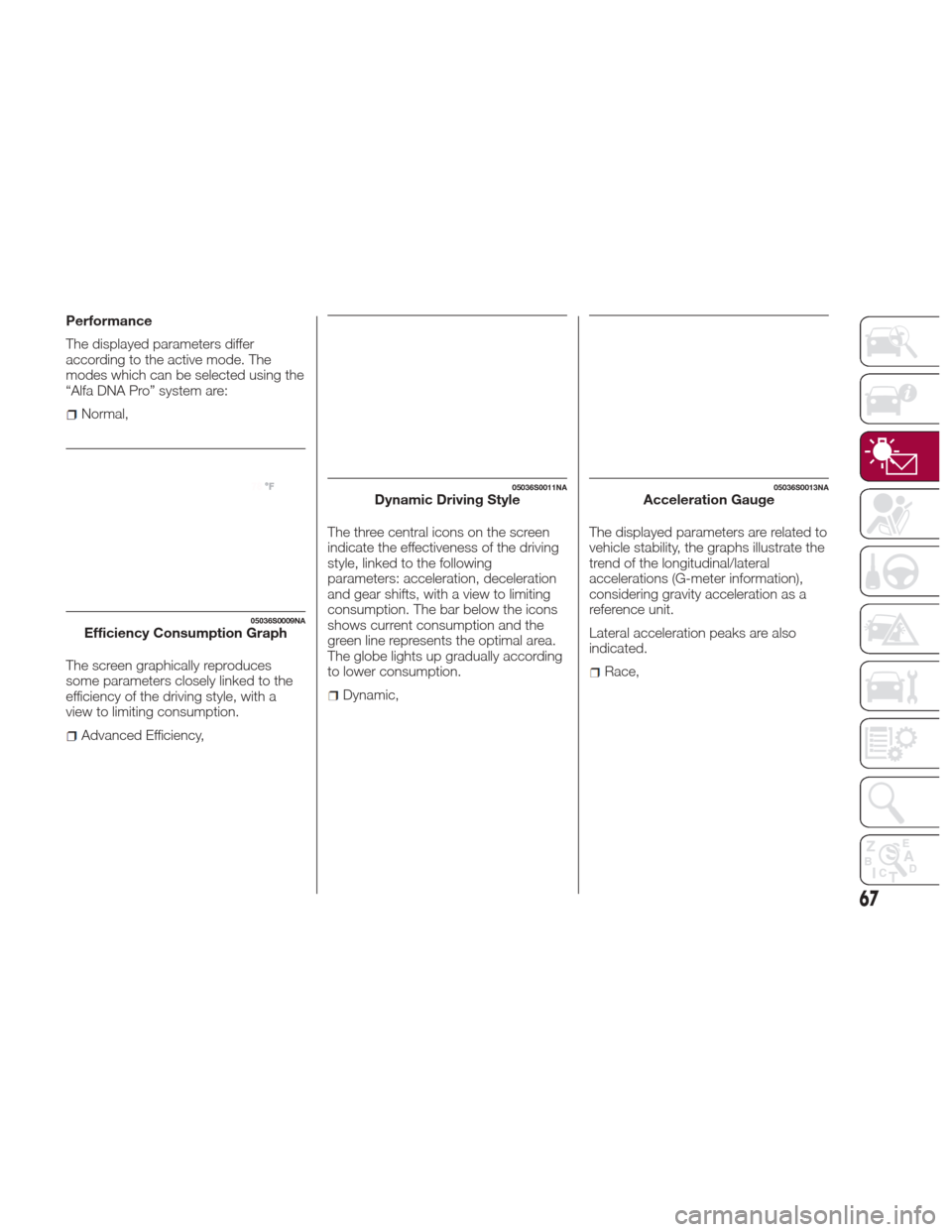
Performance
The displayed parameters differ
according to the active mode. The
modes which can be selected using the
“Alfa DNA Pro” system are:
Normal,
The screen graphically reproduces
some parameters closely linked to the
efficiency of the driving style, with a
view to limiting consumption.
Advanced Efficiency, The three central icons on the screen
indicate the effectiveness of the driving
style, linked to the following
parameters: acceleration, deceleration
and gear shifts, with a view to limiting
consumption. The bar below the icons
shows current consumption and the
green line represents the optimal area.
The globe lights up gradually according
to lower consumption.
Dynamic,
The displayed parameters are related to
vehicle stability, the graphs illustrate the
trend of the longitudinal/lateral
accelerations (G-meter information),
considering gravity acceleration as a
reference unit.
Lateral acceleration peaks are also
indicated.
Race,
05036S0009NAEfficiency Consumption Graph
05036S0011NADynamic Driving Style05036S0013NAAcceleration Gauge
67
Page 70 of 268
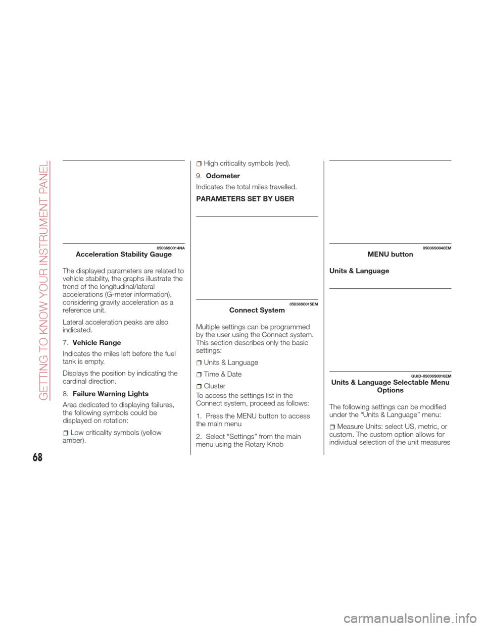
The displayed parameters are related to
vehicle stability, the graphs illustrate the
trend of the longitudinal/lateral
accelerations (G-meter information),
considering gravity acceleration as a
reference unit.
Lateral acceleration peaks are also
indicated.
7.Vehicle Range
Indicates the miles left before the fuel
tankisempty.
Displays the position by indicating the
cardinal direction.
8. Failure Warning Lights
Area dedicated to displaying failures,
the following symbols could be
displayed on rotation:
Low criticality symbols (yellow
amber).
High criticality symbols (red).
9. Odometer
Indicates the total miles travelled.
PARAMETERS SET BY USER
Multiple settings can be programmed
by the user using the Connect system.
This section describes only the basic
settings:
Units & Language
Time&Date
Cluster
To access the settings list in the
Connect system, proceed as follows:
1. Press the MENU button to access
the main menu
2. Select “Settings” from the main
menu using the Rotary Knob Units & Language
The following settings can be modified
under the “Units & Language” menu:
Measure Units: select US, metric, or
custom. The custom option allows for
individual selection of the unit measures
05036S0014NAAcceleration Stability Gauge
05036S0015EMConnect System
05036S0040EMMENU button
GUID-05036S0016EMUnits & Language Selectable Menu Options
68
GETTING TO KNOW YOUR INSTRUMENT PANEL
Page 72 of 268
WARNING LIGHTS
AND MESSAGES ON
THE INSTRUMENT
PANEL
The following pages consist of warning
lights and messages.
Note:
The warning light switches on
together with a dedicated message
and/or chime when applicable. These
indications are precautionary and as
such must not be considered as
exhaustive and/or alternative to the
information contained in the Owner’s
Manual, which you are advised to read
carefully in all cases. Always refer to
the information in this section in the
event of a failure indication.
The failure indicators appearing on
the display are divided into two
categories: very serious and less
serious faults. Serious faults are
indicated by a repeated and prolonged
warning "cycle.” Less serious faults are
indicated by a warning "cycle" with a
shorter duration. You can stop the
warning cycle in both cases by
pressing the button located on the
windshield wiper lever. The instrument
panel warning light will stay on until the
cause of the failure is eliminated.
70
GETTING TO KNOW YOUR INSTRUMENT PANEL
Page 73 of 268

Red Warning Lights
Warning LightWhat It Means What To Do
INSUFFICIENT BRAKE FLUID / ELECTRIC PARK
BRAKE ON
This light monitors various brake functions, including
brake fluid level and parking brake application. If the
brake light turns on it may indicate that the parking
brake is applied, that the brake fluid level is low, or that
there is a problem with the anti-lock brake system
reservoir.
If the light remains on when the parking brake has been
disengaged, and the fluid level is at the full mark on the
master cylinder reservoir, it indicates a possible brake
hydraulic system malfunction or that a problem with the
Brake Booster has been detected by the Anti-Lock
Brake System (ABS) / Electronic Stability Control (ESC)
system. In this case, the light will remain on until the
condition has been corrected. If the problem is related
to the Brake Booster, the ABS pump will run when
applying the brake, and a brake pedal pulsation may be
felt during each stop.For low brake fluid level, go to an authorized dealer to
have the system checked as soon as possible.
Release the electric park brake, then check that the
warning light has switched off.
If the warning light stays on, contact an authorized
dealer.
ELECTRONIC BRAKING FORCE DISTRIBUTION (EBD)
FAILURE
The simultaneous switching on of the BRAKE (red) and
(amber) warning lights with the engine on indicates
either a failure of the EBD system or that the system is
not available. In this case, the rear wheels may suddenly
lock and the vehicle may swerve when braking abruptly. Drive very carefully to the nearest authorized dealer to
have the system inspected immediately.
71
Page 76 of 268
Amber Warning Lights
Warning LightWhat It Means What To Do
ANTI-LOCK ABS INDICATOR LIGHT
This light monitors the Anti-Lock Brake System (ABS).
The light will turn on when the ignition is placed in the
ON/RUN position and may stay on for as long as four
seconds.
If the ABS light remains on or turns on while driving,
then the Anti-Lock portion of the brake system is not
functioning and service is required. However, the
conventional brake system will continue to operate
normally if the brake warning light is not on.
If the ABS light is on, the brake system should be
serviced as soon as possible to restore the benefits of
Anti-Lock Brakes. If the ABS light does not turn on
when the ignition is placed in the ON/RUN position,
have the light inspected by an authorized dealer.Drive carefully and contact an authorized dealer as soon
as possible.
74
GETTING TO KNOW YOUR INSTRUMENT PANEL

