Page 209 of 265

Driving and operating207the charge cord indicators will
indicate an electrical system fault
and the vehicle may not charge.
1. Vehicle plug
2. Protective cover
3. Status indicators
4. Wall plug
Charge cord status indicators
After plugging in the charge cord, it will perform a quick self test.
Verify the charge cord status.
● c illuminates green and d is off,
the charge cord is ready to
charge the vehicle.
● c flashing green and d is off:
Electrical outlet/plug fault: The
charge cord has detected that the electrical outlet/plug overheated.
Use another electrical outlet or have the electrical outlet serviced
by a qualified electrician. Reset
the charge cord by unplugging
the charge cord from the
electrical outlet and re-plugging
it.
● c is off and d flashes red:
Vehicle fault: The charge cord
ground-fault circuit interrupter
has tripped. Ensure that there is no physical damage to the
charge cord and that the vehicle
plug is seated completely and making a good connection. Reset the charge cord by unplugging
from the electrical outlet and re- plugging it. If the fault remains,
consult a workshop for a service
● c solid green and d flashes red:
charge cord fault: The charge
cord has detected a potentialproblem with the charge cord.
Reset the charge cord by
unplugging from the electrical outlet and re-plugging it. If the
fault remains, seek the
assistance of a workshop.
If no status indicator is lit, ensure the electrical outlet is powered.
Charge level selection9 Warning
If the capacity of the electrical
circuit or AC socket is not known,
only use the lowest charge level
until the circuit capacity has been
inspected by a qualified
electrician. Using a charge level
that exceeds either the electrical
circuit or the AC outlet capacity
may start a fire or damage the
electrical circuit.
Page 210 of 265

208Driving and operatingNote
By choosing a reduced charge level,
the charging time is increased.
Charge limit selection can be made
using the Charge limit preference
screen on the Info display. Charge limit selection 3 197.
Grounding instructions This product must be grounded. If thisproduct should malfunction or break
down, grounding provides a path of
least resistance for electric current to
reduce the risk of electric shock. This
product is equipped with a cord that
has an equipment grounding
conductor and a grounding plug. The plug must be plugged into an
appropriate outlet that is properly
installed and grounded in accordance with all local codes and ordinances.9 Warning
Improper connection of the charge
cord ground may cause electrical
shock. Check with a qualified
electrician if there is doubt as to
whether the charge circuit is
properly grounded. Do not modify
the plug provided with the product.
If it will not fit the electrical outlet,
have a proper electrical outlet
installed by a qualified electrician.
Charge cord mounting
instructions
Choose an appropriate, solid location for mounting the charge cord. The
appropriate height for mounting the
charge cord is 91 cm from the floor.
Space the holes 18.7 cm apart.
Install the mounting screws leaving
the head of the screws 5 mm from the
surface.
Securely mount the charge cord on to
the screws.
Connect the wall plug to the electrical
outlet.
Connect the vehicle plug to the
charge port.
Electrical requirementsCaution
Do not use portable or stationary
backup generating equipment to charge the vehicle. This may
cause damage to the vehicle's
charging system. Only charge the
vehicle from utility supplied power.
Charge limit selection 3 197.
Reduced limit mode allows a non-
dedicated circuit to be used but
increases the charging time.
This vehicle is capable of being
charged with standard vehicle
charging equipment complying with
one or more of the following
standards:
● SAE J1772
● SAE J2847–2
● IEC 61851-1
● IEC 61851-22
● IEC 61851-23
● IEC 61851-24
● IEC 62196-1
Page 211 of 265
Driving and operating209● IEC 62196-2
● IEC 62196-3
● ISO 15118
Ensure that all local electrical code/ standards are being met for a
10 ampere continuous load. Always
follow the charging equipment
installation instructions. Contact a
workshop for more information.9 Warning
If the capacity of the electrical
circuit or AC socket is not known,
only use the lowest charge level
until the circuit capacity has been
inspected by a qualified
electrician. Using a charge level
that exceeds either the electrical
circuit or the AC outlet capacity
may start a fire or damage the
electrical circuit.
Towing
General information
The vehicle is neither designed nor
intended to tow a trailer or another vehicle.
Page 212 of 265

210Vehicle careVehicle careGeneral Information...................210
Accessories and vehicle modifications .......................... 210
Lifting the vehicle .....................211
Vehicle storage ........................211
Vehicle checks ........................... 213
Performing work ......................213
Bonnet ..................................... 213
Cooling system ........................214
Washer fluid ............................ 216
Brakes ..................................... 216
Brake fluid ............................... 217
Vehicle battery ......................... 217
Wiper blade replacement ........219
Headlight aiming ......................219
Bulb replacement .......................220
Halogen bulbs ......................... 220
Xenon headlights .....................220
Front turn signal lights .............220
Tail lights ................................. 221
Side turn signal lights ..............221
Number plate light ...................221
Electrical system ........................222
High voltage devices and wiring ...................................... 222Electrical system overload .......222
Fuses ....................................... 223
Engine compartment fuse box . 224
Instrument panel fuse box .......227
Vehicle tools .............................. 230
Tools ........................................ 230
Wheels and tyres .......................230
Tyres ....................................... 230
Winter tyres ............................. 231
Tyre designations ....................231
Tyre pressure .......................... 231
Tyre pressure monitoring system .................................... 233
Tread depth ............................. 235
Changing tyre and wheel size . 235
Wheel covers ........................... 236
Tyre chains .............................. 236
Jump starting ............................. 237
Towing ....................................... 239
Towing the vehicle ...................239
Towing another vehicle ...........240
Appearance care .......................240
Exterior care ............................ 240
Interior care ............................. 242General Information
Accessories and vehicle modifications
We recommend the use of genuine
parts and accessories and factory
approved parts specific for your
vehicle type. We cannot assess or
guarantee reliability of other products
- even if they have a regulatory or
otherwise granted approval.
Any modification, conversion or other changes made to standard vehicle
specifications (including, without
limitation, software modifications,
modifications of the electronic control
units) may invalidate the warranty
offered by Opel. Furthermore, such
changes may affect driver assistance systems and cause the vehicle to no
longer conform to the operating
permit, impacting the validity of your
vehicle registration.
Page 213 of 265

Vehicle care211Caution
When transporting the vehicle on
a train or on a recovery vehicle, the
mud flaps might be damaged.
Lifting the vehicle
9 Warning
Lifting the vehicle improperly can
cause serious injuries and
damage to the vehicle.
The vehicle should be lifted only by well-trained staff at an
authorised workshop.
Jacking position for lifting platform
Rear arm position of the lifting
platform at the underbody.
Front arm position of the lifting
platform at the underbody.
Ramps may be needed under the
front tyres to provide the necessary
clearance for certain lifting platforms
in this location.
Vehicle storage Storage for a long period of timeIf the vehicle is to be stored for several months:
● Wash and wax the vehicle.
● Have the wax in the engine compartment and underbody
checked.
● Clean and preserve the rubber seals.
● Drain the washer fluid reservoir.
● Check the coolant antifreeze and
corrosion protection.
● Adjust tyre pressure to the value specified for full load.
● Park the vehicle in a dry, well ventilated place. Engage P.
Prevent the vehicle from rolling.
Page 214 of 265

212Vehicle care● Do not apply the parking brake.
● Open the bonnet, close all doors and lock the vehicle.Up to four weeks
Plug in the charge cord.Four weeks to 12 months ● Discharge the high voltage battery until two or three bars
remain on the battery range
indicator (battery symbol) on the
instrument cluster.
● Do not plug in the charge cord
● Always store the vehicle in a place with temperatures between−10 °C and 30 °C.
● Vehicle storage at extreme temperatures may cause
damage to the high voltage
battery.
● Remove the black negative (−) cable from the 12-volt vehicle
battery and attach a trickle
charger to the vehicle battery
terminals or keep the 12-volt vehicle battery cables connected
and trickle charge from thepositive (+) and negative (−)
terminals in the engine
compartment.Caution
The vehicle is equipped with an
AGM 12-volt battery, which can be damaged by using the incorrect
type of trickle charger.
An AGM compatible charger must be used, with the appropriate
setting selected.
Follow the trickle charger
manufacturer instructions.
After the vehicle battery cable is
reconnected, it is possible that the
vehicle may not operate. If this
happens, the high voltage battery
may need to be charged.
Putting back into operation
When the vehicle is to be put back into
operation:
● Connect the clamp to the negative terminal of the vehicle
battery. Activate the electronics
of the power windows.
● Check tyre pressure.
● Fill up the washer fluid reservoir.
● Check the coolant level.
● Fit the number plate if necessary.
Page 215 of 265

Vehicle care213Vehicle checks
Performing work9 Danger
Never try to perform maintenance
work on high voltage battery
components yourself. You may be
injured and the vehicle may be
damaged. Service and repair of
these high voltage battery
components should only be
performed by a trained service
technician with proper knowledge
and tools. Exposure to high
voltage may cause shock, burns,
and even death. The high voltage
components in the vehicle can
only be serviced by technicians
with special training.
High voltage components are
identified by labels. Do not
remove, open, take apart, or
modify these components. High
voltage cable or wiring has orange covering. Do not probe, tamper
with, cut, or modify high voltage
cable or wiring.9 Warning
Only perform engine compartment
checks when the vehicle is off.
The cooling fan may start
operating even if the vehicle is off.
Caution
Even small amounts of contamination can cause damage
to vehicle systems. Do not allow
contaminants to contact the fluids, reservoir caps, or dipsticks.
Bonnet
Opening
1. Pull the release lever and return it
to its original position.
Page 216 of 265
214Vehicle care
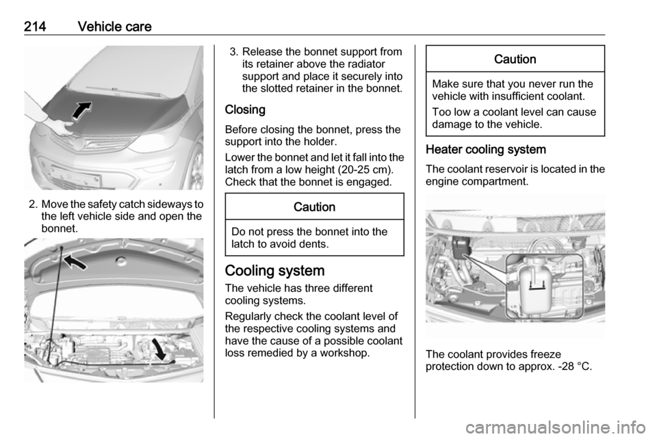
2.Move the safety catch sideways to
the left vehicle side and open the
bonnet.
3. Release the bonnet support from its retainer above the radiator
support and place it securely into
the slotted retainer in the bonnet.
Closing Before closing the bonnet, press the
support into the holder.
Lower the bonnet and let it fall into the latch from a low height (20-25 cm).
Check that the bonnet is engaged.Caution
Do not press the bonnet into the
latch to avoid dents.
Cooling system
The vehicle has three different
cooling systems.
Regularly check the coolant level of
the respective cooling systems and
have the cause of a possible coolant
loss remedied by a workshop.
Caution
Make sure that you never run the
vehicle with insufficient coolant.
Too low a coolant level can cause damage to the vehicle.
Heater cooling system
The coolant reservoir is located in the engine compartment.
The coolant provides freeze
protection down to approx. -28 °C.