Page 57 of 104
Periodic maintenance an d a djustment
6-12
6
TIP
Skip steps 5–7 if the oil filter cartridge
is not being replaced.
5. Remove the oil filter cartridge with
an oil filter wrench.
TIP
An oil filter wrench is available at a
Yamaha dealer.
6. Apply a thin coat of clean engine oil to the O-ring of the new oil filter
cartridge.
TIP
Make sure that the O-ring is properly
seated.
7. Install the new oil filter cartridgewith an oil filter wrench, and then
tighten it to the specified torque
with a torque wrench.
8. Install the engine oil drain bolt and its new gasket, and then tighten
the bolt to the specified torque.
1. Engine oil drain bolt
2. Gasket
1. Oil filter cartridge
2. Oil filter wrench
12
1
2
1. O-ring
1. Torque wrench
Ti ghtenin g torque:
Oil filter cartridge: 17 Nm (1.7 m·kgf, 12 ft·lbf)
Ti ghtenin g torque:
Engine oil drain bolt: 43 Nm (4.3 m·kgf, 31 ft·lbf)
1
UBS1E0E0.book Page 12 Thursday, October 8, 2015 3:40 PM
Page 58 of 104

Periodic maintenance an d a djustment
6-13
6 9. Refill with the specified amount of
the recommended engine oil, and
then install and tighten the oil filler
cap.
TIP
Be sure to wipe off spilled oil on any
parts after the engine and exhaust sys-
tem have cooled down.
NOTICE
ECA11621
In or der to prevent clutch slip-
pa ge (since the en gine oil also
lu bricates the clutch), do not
mix any chemical additives. Do
not use oils with a diesel speci-
fication of “CD” or oils of a hi gh-
er quality than specifie d. In
a ddition, do not use oils la bele d
“ENERGY CONSERVING II” or
hi gher.
Make sure that no forei gn mate-
rial enters the crankcase.
10. Start the engine, and then let it idle for several minutes while checking
it for oil leakage. If oil is leaking,
immediately turn the engine off
and check for the cause.
TIP
After the engine is started, the engine
oil level warning light should go off if
the oil level is sufficient.
NOTICE
ECA10402
If the oil level warnin g li ght flickers
or remains on even if the oil level is
correct, imme diately turn the en gine
off an d have a Yamaha dealer check
the vehicle.
11. Turn the engine off, wait a few minutes until the oil settles, and
then check the oil level and cor-
rect it if necessary.
12. Install the cowling.
Recommen ded en gine oil:
See page 8-1.
Oil quantity: Oil change:
2.50 L (2.64 US qt, 2.20 Imp.qt)
With oil filter removal: 2.80 L (2.96 US qt, 2.46 Imp.qt)
UBS1E0E0.book Page 13 Thursday, October 8, 2015 3:40 PM
Page 59 of 104

Periodic maintenance an d a djustment
6-14
6
EAU20071
Coolant
The coolant level should be checked
before each ride. In addition, the cool-
ant must be changed at the intervals
specified in the periodic maintenance
and lubrication chart.
EAU50543To check the coolant level
1. Place the vehicle on the center- stand.
2. Remove cowling A. (See page 6-7.)
TIP
The coolant level must be
checked on a cold engine since
the level varies with engine tem-
perature.
Make sure that the vehicle is posi-
tioned straight up when checking
the coolant level. A slight tilt to the
side can result in a false reading.
3. Check the coolant level in the
coolant reservoir.
TIP
The coolant should be between the
minimum and maximum level marks.
4. If the coolant is at or below theminimum level mark, remove
cowling C. (See page 6-7.)
5. Remove the coolant reservoir breather hose from the guide, and
then remove the coolant reservoir
cap. WARNING! Remove only
the coolant reservoir cap. Never
attempt to remove the ra diator
cap when the en gine is hot.
[EWA15162]
6. Add coolant to the maximum level
mark, and then install the coolant
reservoir cap. NOTICE: If coolant
is not availa ble, use distille d wa-
ter or soft tap water instea d. Do
not use har d water or salt water
since it is harmful to the en gine.
If water has been used instead
of coolant, replace it with cool-
ant as soon as possi ble, other-
wise the coolin g system will not
b e protecte d a gainst frost an d
corrosion. If water has been
a dd ed to the coolant, have a
Yamaha dealer check the anti-
freeze content of the coolant as
soon as possi ble, otherwise the
effectiveness of the coolant will
b e red uced.
[ECA10473]
1. Coolant reservoir
2. Maximum level mark
3. Minimum level mark
1
2
3
1. Coolant reservoir cap
2. Coolant reservoir breather hose
3. Guide
3
1
2
UBS1E0E0.book Page 14 Thursday, October 8, 2015 3:40 PM
Page 60 of 104

Periodic maintenance an d a djustment
6-15
6 7. Route the coolant reservoir
breather hose through the guide
as shown.
8. Install the cowlings.
EAU50742To chan ge the coolant
1. Place the vehicle on the center- stand and let the engine cool if
necessary.
2. Remove cowlings A and C. (See page 6-7.)
3. Place a container under the en- gine to collect the used coolant.
4. Remove the radiator cap. WARNING! Never attempt to re-move the ra diator cap when the
en gine is hot.
[EWA10382]
5. Remove the coolant reservoir
breather hose from the guide, and
then remove the coolant reservoir
cap.
6. Remove the coolant reservoir cov- er and coolant reservoir by remov-
ing the bolts.
Coolant reservoir capacity (up to
the maximum level mark):0.25 L (0.26 US qt, 0.22 Imp.qt)
1. Coolant reservoir breather hose
2. Guide
2
1
1. Radiator cap
1. Coolant reservoir cap
2. Coolant reservoir breather hose
3. Guide
1. Bolt
2. Coolant reservoir cover
3. Coolant reservoir
1
3
1
2
2
3
1
UBS1E0E0.book Page 15 Thursday, October 8, 2015 3:40 PM
Page 61 of 104

Periodic maintenance an d a djustment
6-16
6
7. Drain the coolant from the coolant
reservoir by turning it upside
down.
8. Remove the coolant drain bolt and its gasket to drain the cooling sys-
tem.
9. After the coolant is completely drained, thoroughly flush the cool-
ing system with clean tap water.
10. Install the coolant drain bolt and its new gasket, and then tighten
the bolt to the specified torque.
11. Install the coolant reservoir and its cover by placing them in the origi-
nal position, and then installing the
bolts.
12. Pour the specified amount of the recommended coolant into the ra-
diator and reservoir. 13. Install the radiator cap.
14. Install the coolant reservoir cap.
15. Start the engine, let it idle for sev-
eral minutes, and then turn it off.
16. Remove the radiator cap to check the coolant level in the radiator. If
necessary, add sufficient coolant
until it reaches the top of the radi-
ator, and then install the radiator
cap.
17. Check the coolant level in the res- ervoir. If necessary, remove the
coolant reservoir cap, add coolant
to the maximum level mark, and
then install the cap.
18. Route the coolant reservoir breather hose through the guide
as shown.
1. Coolant drain bolt
2. Gasket
Tightening torque:
Coolant drain bolt: 10 Nm (1.0 m·kgf, 7.2 ft·lbf)
21
Antifreeze/water mixture ratio:
1:1
Recommen ded antifreeze:
High-quality ethylene glycol anti-
freeze containing corrosion inhibi-
tors for aluminum engines
Coolant quantity:
Radiator (including all routes): 2.00 L (2.11 US qt, 1.76 Imp.qt)
Coolant reservoir (up to the maxi-
mum level mark): 0.25 L (0.26 US qt, 0.22 Imp.qt)
1. Coolant reservoir breather hose
2. Guide
2
1
UBS1E0E0.book Page 16 Thursday, October 8, 2015 3:40 PM
Page 62 of 104
Periodic maintenance an d a djustment
6-17
6 19. Start the engine, and then check
the vehicle for coolant leakage. If
coolant is leaking, have a Yamaha
dealer check the cooling system.
20. Install the cowlings.
EAU32888
Replacin g the air filter ele-
ment
The air filter element should be re-
placed at the intervals specified in the
periodic maintenance and lubrication
chart. Replace the air filter element
more frequently if you are riding in un-
usually wet or dusty areas.
1. Remove the seat. (See page 3-18.)
2. Remove panels B and C. (See page 6-7.)
3. Remove the fuel tank bolts, and then lift the fuel tank away from
the air filter case.
4. Remove the air filter case cover by removing the screws. NOTICE:
When removin g the air filter
case cover, b e careful not to al-
low forei gn o bjects to d rop into
the air intake manifol d.
[ECA12882]
1. Fuel tank bolt
1
UBS1E0E0.book Page 17 Thursday, October 8, 2015 3:40 PM
Page 63 of 104

Periodic maintenance an d a djustment
6-18
6
5. Pull the air filter element out.
6. Insert a new air filter element into
the air filter case. NOTICE: Make
sure that the air filter element is
properly seated in the air filter
case. The en gine shoul d never
b e operated without the air filter
element installed , otherwise the
piston(s) an d/or cylin der(s) may
b ecome excessively worn.
[ECA10482]
7. Install the air filter case cover by
installing the screws.
8. Place the fuel tank in its original position. Make sure that the fuel
hoses are properly connected and
routed, and are not pinched. Be
sure to place the hoses in their
original position. WARNING! Be- fore placin
g the fuel tank in the
ori ginal position, make sure that
all hoses (i.e., fuel hose, fuel
tank breather hose, fuel tank
overflow hose) are not dam-
a g ed , that they are properly
connected and route d, an d that
they are not pinche d. If any hose
is damag ed , have a Yamaha
d ealer replace the hose before
startin g the en gine, otherwise
fuel may leak, creatin g a fire
hazar d.
[EWA12464]
9. Install the fuel tank bolts.
10. Install the panels.
11. Install the seat.
1. Air filter case cover
2. Screw
1. Air filter element
2. Air intake manifold
1 2
2
2
2
1
1. Hose
1. Original position (paint mark)
1
1
UBS1E0E0.book Page 18 Thursday, October 8, 2015 3:40 PM
Page 64 of 104

Periodic maintenance an d a djustment
6-19
6
EAU34302
A djustin g the en gine i dlin g
spee d
The engine idling speed must be
checked and, if necessary, adjusted as
follows at the intervals specified in the
periodic maintenance and lubrication
chart.
The engine should be warm before
making this adjustment.
Check the engine idling speed and, if
necessary, adjust it to specification by
turning the idle adjusting screw. To in-
crease the engine idling speed, turn the
screw in direction (a). To decrease the
engine idling speed, turn the screw in
direction (b).
TIP
If the specified idling speed cannot be
obtained as described above, have a
Yamaha dealer make the adjustment.
EAU21386
Checkin g the throttle grip free
play
Measure the throttle grip free play as
shown.
Periodically check the throttle grip free
play and, if necessary, have a Yamaha
dealer adjust it.
1. Idle adjusting screw
En gine i dlin g spee d:
1250–1350 r/min
1
(a)
(b)
1. Throttle grip free play
Throttle g rip free play:
3.0–5.0 mm (0.12–0.20 in)
UBS1E0E0.book Page 19 Thursday, October 8, 2015 3:40 PM
 1
1 2
2 3
3 4
4 5
5 6
6 7
7 8
8 9
9 10
10 11
11 12
12 13
13 14
14 15
15 16
16 17
17 18
18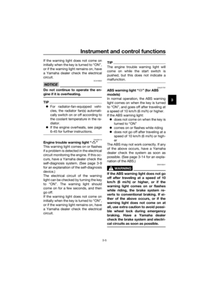 19
19 20
20 21
21 22
22 23
23 24
24 25
25 26
26 27
27 28
28 29
29 30
30 31
31 32
32 33
33 34
34 35
35 36
36 37
37 38
38 39
39 40
40 41
41 42
42 43
43 44
44 45
45 46
46 47
47 48
48 49
49 50
50 51
51 52
52 53
53 54
54 55
55 56
56 57
57 58
58 59
59 60
60 61
61 62
62 63
63 64
64 65
65 66
66 67
67 68
68 69
69 70
70 71
71 72
72 73
73 74
74 75
75 76
76 77
77 78
78 79
79 80
80 81
81 82
82 83
83 84
84 85
85 86
86 87
87 88
88 89
89 90
90 91
91 92
92 93
93 94
94 95
95 96
96 97
97 98
98 99
99 100
100 101
101 102
102 103
103
