Page 65 of 104

Periodic maintenance an d a djustment
6-20
6
EAU21402
Valve clearance
The valve clearance changes with use,
resulting in improper air-fuel mixture
and/or engine noise. To prevent this
from occurring, the valve clearance
must be adjusted by a Yamaha dealer
at the intervals specified in the periodic
maintenance and lubrication chart.
EAU64270
Tires
Tires are the only contact between the
vehicle and the road. Safety in all con-
ditions of riding depends on a relatively
small area of road contact. Therefore, it
is essential to maintain the tires in good
condition at all times and replace them
at the appropriate time with the speci-
fied tires.
Tire air pressure
The tire air pressure should be
checked and, if necessary, adjusted
before each ride.
WARNING
EWA10504
Operation of this vehicle with im-
proper tire pressure may cause se-
vere injury or d eath from loss of
control. The tire air pressure must b e
checked and a djuste d on col d
tires (i.e., when the temperature
of the tires equals the am bient
temperature).
The tire air pressure must b e
a d juste d in accor dance with the
ri din g speed and with the total
wei ght of ri der, passen ger, car-
g o, an d accessories approve d
for this mo del.
UBS1E0E0.book Page 20 Thursday, October 8, 2015 3:40 PM
Page 66 of 104

Periodic maintenance an d a djustment
6-21
6
WARNING
EWA10512
Never overloa d your vehicle. Opera-
tion of an overloa ded vehicle coul d
cause an acci dent.
Tire inspection
The tires must be checked before each
ride. If the center tread depth reaches
the specified limit, if the tire has a nail
or glass fragments in it, or if the side-
wall is cracked, have a Yamaha dealer
replace the tire immediately.
TIP
The tire tread depth limits may differ
from country to country. Always com-
ply with the local regulations.
WARNING
EWA10472
Have a Yamaha dealer replace
excessively worn tires. Besi des
b ein g ille gal, operatin g the vehi-
cle with excessively worn tires
d ecreases ri din g sta bility an d
can lead to loss of control.
The replacement of all wheel
and b rake-related parts, includ-
in g the tires, shoul d b e left to a
Yamaha dealer, who has the
necessary professional knowl-
e dge an d experience to do so.
Ride at mo derate spee ds after
chan gin g a tire since the tire
surface must first b e “broken
in” for it to develop its optimal
characteristics.
Tire information
Tire air pressure (measure d on col d
tires): Up to 90 k g (198 l b) loa d:
Front:
225 kPa (2.25 kgf/cm², 33 psi)
Rear: 250 kPa (2.50 kgf/cm², 36 psi)
90 k g (198 l b) to maximum loa d:
Front: 250 kPa (2.50 kgf/cm², 36 psi)
Rear: 290 kPa (2.90 kgf/cm², 42 psi)
Maximum load *:
180 kg (397 lb) (XJ6FA)
185 kg (408 lb) (XJ6F)
* Total weight of rider, passenger, car-
go and accessories
1. Tire sidewall
2. Tire tread depth
Minimum tire trea d d epth (front an d
rear): 1.6 mm (0.06 in)
1. Tire air valve
2. Tire air valve core
3. Tire air valve cap with seal
UBS1E0E0.book Page 21 Thursday, October 8, 2015 3:40 PM
Page 67 of 104

Periodic maintenance an d a djustment
6-22
6
This model is equipped with tubeless
tires and tire air valves.
Tires age, even if they have not been
used or have only been used occasion-
ally. Cracking of the tread and sidewall
rubber, sometimes accompanied by
carcass deformation, is an evidence of
ageing. Old and aged tires shall be
checked by tire specialists to ascertain
their suitability for further use.
WARNING
EWA10902
The front an d rear tires shoul d
b e of the same make an d d e-
si gn, otherwise the han dlin g
characteristics of the motorcy-
cle may b e different, which
coul d lea d to an acci dent.
Always make sure that the valve
caps are securely installe d to
prevent air pressure leakag e.
Use only the tire valves an d
valve cores liste d below to
avoi d tire deflation during a ride.
After extensive tests, only the tires list-
ed below have been approved for this
model by Yamaha.
WARNING
EWA10601
This motorcycle is fitte d with super-
hi gh-spee d tires. Note the followin g
points in or der to make the most ef-
ficient use of these tires. Use only the specifie d replace-
ment tires. Other tires may run
the dan ger of bursting at super
hi gh spee ds.
Bran d-new tires can have a rel-
atively poor g rip on certain road
surfaces until they have been
“ b roken in”. Therefore, it is a d-
visa ble before doin g any hi gh-
speed ridin g to ri de conserva-
tively for approximately 100 km
(60 mi) after installin g a new tire.
The tires must b e warmed up
b efore a hi gh-spee d run.
Always a djust the tire air pres-
sure accor din g to the operating
con ditions.
Front tire:
Size: 120/70 ZR17M/C (58W)
Manufacturer/model:
BRIDGESTONE/BT021
DUNLOP/ROADSMART
Rear tire:
Size: 160/60 ZR17M/C (69W)
Manufacturer/model:
BRIDGESTONE/BT021
DUNLOP/ROADSMART
FRONT and REAR:
Tire air valve: TR412
Valve core:
#9100 (original)
UBS1E0E0.book Page 22 Thursday, October 8, 2015 3:40 PM
Page 68 of 104

Periodic maintenance an d a djustment
6-23
6
EAU21963
Cast wheels
To maximize the performance, durabil-
ity, and safe operation of your vehicle,
note the following points regarding the
specified wheels.
The wheel rims should be
checked for cracks, bends, warp-
age or other damage before each
ride. If any damage is found, have
a Yamaha dealer replace the
wheel. Do not attempt even the
smallest repair to the wheel. A de-
formed or cracked wheel must be
replaced.
The wheel should be balanced
whenever either the tire or wheel
has been changed or replaced. An
unbalanced wheel can result in
poor performance, adverse han-
dling characteristics, and a short-
ened tire life.
EAU47392
Adjustin g the clutch lever free
play
Measure the clutch lever free play as
shown.
Periodically check the clutch lever free
play and, if necessary, adjust it as fol-
lows.
To increase the clutch lever free play,
turn the clutch lever free play adjusting
bolt at the clutch lever in direction (a).
To decrease the clutch lever free play,
turn the adjusting bolt in direction (b).
TIP
If the specified clutch lever free play
cannot be obtained as described
above, proceed as follows.
1. Fully turn the adjusting bolt at the
clutch lever in direction (a) to loos-
en the clutch cable.
2. Remove cowlings A and B. (See page 6-7.)
3. Loosen the locknut further down the clutch cable.
1. Clutch lever free play adjusting bolt
2. Clutch lever free play
Clutch lever free play:10.0–15.0 mm (0.39–0.59 in)
UBS1E0E0.book Page 23 Thursday, October 8, 2015 3:40 PM
Page 69 of 104
Periodic maintenance an d a djustment
6-24
6
4. To increase the clutch lever free
play, turn the clutch lever free play
adjusting nut in direction (a). To
decrease the clutch lever free
play, turn the adjusting nut in di-
rection (b).
5. Tighten the locknut.
6. Install the cowlings.
EAU37914
Checkin g the brake lever free
play
There should be no free play at the
brake lever end. If there is free play,
have a Yamaha dealer inspect the
brake system.
WARNING
EWA14212
A soft or spon gy feelin g in the brake
lever can in dicate the presence of
air in the hy draulic system. If there is
air in the hy draulic system, have a
Yamaha dealer blee d the system b e-
fore operatin g the vehicle. Air in the
hy draulic system will diminish the
b rakin g performance, which may re-
sult in loss of control an d an acci-
d ent.
1. Locknut
2. Clutch lever free play adjusting nut
1 2
(a)
(b)
1. No brake lever free play
1
UBS1E0E0.book Page 24 Thursday, October 8, 2015 3:40 PM
Page 70 of 104

Periodic maintenance an d a djustment
6-25
6
EAU57070
Brake li ght switches
For non-ABS mo dels
The brake light, which is activated by
the brake pedal and brake lever,
should come on just before braking
takes effect. If necessary, adjust the
rear brake light switch as follows, but
the front brake light switch should be
adjusted by a Yamaha dealer.
Turn the rear brake light switch adjust-
ing nut while holding the rear brake
light switch in place. To make the
brake light come on earlier, turn the ad-
justing nut in direction (a). To make the
brake light come on later, turn the ad-
justing nut in direction (b).
For ABS mo dels
The brake light, which is activated by
the brake pedal and brake lever,
should come on just before braking
takes effect. If necessary, have a
Yamaha dealer adjust the brake light switches.
EAU22393
Checkin g the front an d rear
b rake pa ds
The front and rear brake pads must be
checked for wear at the intervals spec-
ified in the periodic maintenance and
lubrication chart.
EAU22421Front brake pa ds
Each front brake pad is provided with a
wear indicator groove, which allows
you to check the brake pad wear with-
out having to disassemble the brake.
To check the brake pad wear, check
the wear indicator groove. If a brake
pad has worn to the point that the wear
indicator groove has almost disap-
peared, have a Yamaha dealer replace
the brake pads as a set.
1. Rear brake light switch
2. Rear brake light switch adjusting nut
1
2
(a)
(b)
1. Brake pad wear indicator groove
11
UBS1E0E0.book Page 25 Thursday, October 8, 2015 3:40 PM
Page 71 of 104

Periodic maintenance an d a djustment
6-26
6
EAU46292Rear brake pa ds
Each rear brake pad is provided with
wear indicator grooves, which allow
you to check the brake pad wear with-
out having to disassemble the brake.
To check the brake pad wear, check
the wear indicator grooves. If a brake
pad has worn to the point that a wear
indicator groove almost appears, have
a Yamaha dealer replace the brake
pads as a set.EAU43113
Checkin g the brake flui d level
Before riding, check that the brake fluid
is above the minimum level mark.
Check the brake fluid level with the top
of the reservoir level. Replenish the
brake fluid if necessary.
Front brake
Rear brake
TIP
The rear brake fluid reservoir is located
behind panel A. (See page 6-7.)
WARNING
EWA16011
Improper maintenance can result in
loss of b raking a bility. O bserve
these precautions:
1. Brake pad wear indicator groove
11
1. Minimum level mark
1. Minimum level mark
Specified b rake flui d:
DOT 4
1
UBS1E0E0.book Page 26 Thursday, October 8, 2015 3:40 PM
Page 72 of 104

Periodic maintenance an d a djustment
6-27
6
Insufficient brake flui d may al-
low air to enter the brake sys-
tem, re ducing brakin g
performance.
Clean the filler cap before re-
movin g. Use only DOT 4 b rake
flui d from a seale d container.
Use only the specifie d b rake flu-
i d ; otherwise, the ru bber seals
may deteriorate, causin g leak-
a g e.
Refill with the same type of
brake flui d. A ddin g a b rake flui d
other than DOT 4 may result in a
harmful chemical reaction.
Be careful that water or dust
d oes not enter the brake flui d
reservoir when refillin g. Water
will si gnificantly lower the boil-
in g point of the flui d an d may re-
sult in vapor lock, an d d irt may
clo g the ABS hy draulic unit
valves.
NOTICE
ECA17641
Brake flui d may damag e painte d
surfaces or plastic parts. Always
clean up spille d flui d imme diately.
As the brake pads wear, it is normal for
the brake fluid level to gradually go
down. A low brake fluid level may indi-
cate worn brake pads and/or brake
system leakage; therefore, be sure to
check the brake pads for wear and the
brake system for leakage. If the brake
fluid level goes down suddenly, have a
Yamaha dealer check the cause before further riding.
EAU22733
Chan gin g the brake flui d
Have a Yamaha dealer change the
brake fluid at the intervals specified in
the periodic maintenance and lubrica-
tion chart. In addition, have the oil seals
of the master cylinders and calipers as
well as the brake hoses replaced at the
intervals listed below or whenever they
are damaged or leaking.
Oil seals: Replace every two
years.
Brake hoses: Replace every four
years.
UBS1E0E0.book Page 27 Thursday, October 8, 2015 3:40 PM
 1
1 2
2 3
3 4
4 5
5 6
6 7
7 8
8 9
9 10
10 11
11 12
12 13
13 14
14 15
15 16
16 17
17 18
18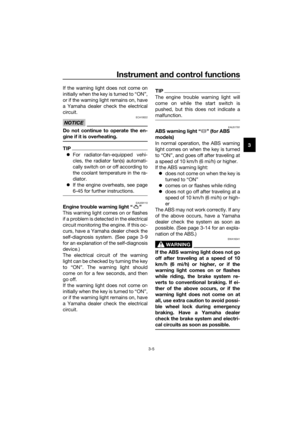 19
19 20
20 21
21 22
22 23
23 24
24 25
25 26
26 27
27 28
28 29
29 30
30 31
31 32
32 33
33 34
34 35
35 36
36 37
37 38
38 39
39 40
40 41
41 42
42 43
43 44
44 45
45 46
46 47
47 48
48 49
49 50
50 51
51 52
52 53
53 54
54 55
55 56
56 57
57 58
58 59
59 60
60 61
61 62
62 63
63 64
64 65
65 66
66 67
67 68
68 69
69 70
70 71
71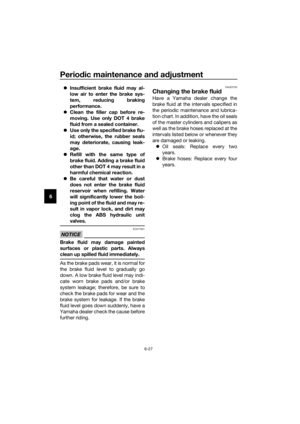 72
72 73
73 74
74 75
75 76
76 77
77 78
78 79
79 80
80 81
81 82
82 83
83 84
84 85
85 86
86 87
87 88
88 89
89 90
90 91
91 92
92 93
93 94
94 95
95 96
96 97
97 98
98 99
99 100
100 101
101 102
102 103
103. To
decrease the clutch lever free
play, turn the")