2016 VOLVO XC90 T8 steering wheel
[x] Cancel search: steering wheelPage 284 of 546
DRIVER SUPPORT
282
Other Adaptive Cruise Control (ACC) functions
ACC has several supplementary functions:
• Changing target vehicles
• Automatic standby mode when changing tar- gets
• Auto-hold brake function
• Deactivation of the auto-hold brake function
• Automatically setting the parking brake
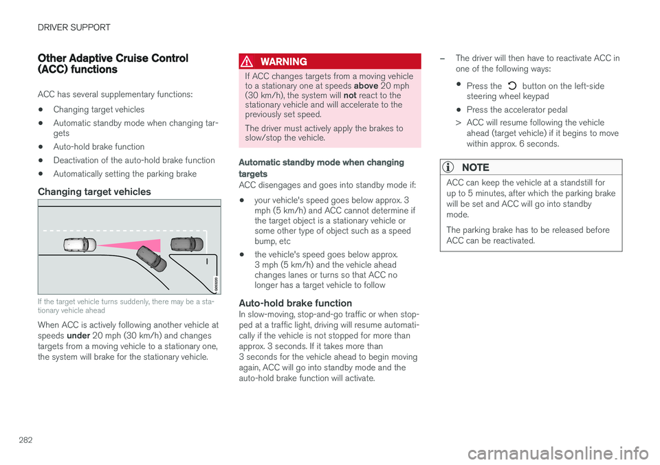
Changing target vehicles
If the target vehicle turns suddenly, there may be a sta- tionary vehicle ahead
When ACC is actively following another vehicle at speeds
under 20 mph (30 km/h) and changes
targets from a moving vehicle to a stationary one, the system will brake for the stationary vehicle.
WARNING
If ACC changes targets from a moving vehicle to a stationary one at speeds above 20 mph
(30 km/h), the system will not react to the
stationary vehicle and will accelerate to the previously set speed. The driver must actively apply the brakes to slow/stop the vehicle.
Automatic standby mode when changing targets
ACC disengages and goes into standby mode if:
• your vehicle's speed goes below approx. 3 mph (5 km/h) and ACC cannot determine ifthe target object is a stationary vehicle orsome other type of object such as a speedbump, etc
• the vehicle's speed goes below approx.3 mph (5 km/h) and the vehicle aheadchanges lanes or turns so that ACC nolonger has a target vehicle to follow
Auto-hold brake functionIn slow-moving, stop-and-go traffic or when stop- ped at a traffic light, driving will resume automati-cally if the vehicle is not stopped for more thanapprox. 3 seconds. If it takes more than3 seconds for the vehicle ahead to begin movingagain, ACC will go into standby mode and theauto-hold brake function will activate.
–The driver will then have to reactivate ACC in one of the following ways:
• Press the
button on the left-side
steering wheel keypad
• Press the accelerator pedal
> ACC will resume following the vehicle ahead (target vehicle) if it begins to move
within approx. 6 seconds.
NOTE
ACC can keep the vehicle at a standstill for up to 5 minutes, after which the parking brakewill be set and ACC will go into standbymode. The parking brake has to be released before ACC can be reactivated.
Page 287 of 546

DRIVER SUPPORT
* Option/accessory, for more information, see Introduction.285
Adaptive Cruise Control (ACC) - fault tracing
If this symbol is displayed in the instru- ment panel and the message
Windscreen sensor Sensor
blocked, see Owner's manual
appears, the ACC radar sensor is blocked and cannot detect vehicles ahead.
This message also indicates that the following systems may have reduced functionality:
• Distance Alert
• City Safety
• Driver Alert Control
• Pilot Assist
• Lane Departure Warning (LDW) •
Lane Keeping Aid (LKA)
• Traffic Sign Information (TSI)
The following table lists possible causes for thismessage being displayed and suitable actions:
CauseAction
The windshield in front of the radar is dirty or covered with snow/ice.Clean/clear the windshield in front of the radar.
Heavy rain or snow is interfering with the radar signals.No action possible. Heavy precipitation may affect the function of the radar.
Swirling water or snow from the surface of the road may interfere with the radar signals.No action possible. A very wet or snow-covered road surface may affect the function of the radar.
The windshield in front of the radar is clean but the message remains in the display.Wait a short time. It may take several minutes for the radar to detect that it is no longer obstructed.
A text message can be erased by briefly pressing the O button on the right-side steering wheel
keypad. If the message recurs, contact a trained and authorized Volvo service technician orretailer.
Related information
• Adaptive Cruise Control (ACC)
* (p. 266)
Page 295 of 546

DRIVER SUPPORT
}}
293
Related information
•City Safety
™ (p. 287)
• Whiplash protection system (p. 63)
• Seat belts (p. 64)
• City Safety warning level settings (p. 289)
City Safety limitations
City Safety ™ may have limited or reduced func-
tionality in certain situations.
The function has several limitations that the driver should be familiar with:
Low objects
Hanging objects, such as flags for overhanging loads or accessories such as auxiliary lights orfront protective grids that extend beyond theheight of the hood may limit City Safety's func-tion.
Slippery driving conditions
The extended braking distance on slippery roads may reduce City Safety's capacity to help avoid acollision. In situations of this type, the ABSbrakes and Electronic Stability Control will helpprovide braking power and stability.
Backlighting
Strong sunlight, reflections, extreme light con- trasts, the use of sunglasses, or if the driver is notlooking straight ahead may make the visual warn-ing signal in the windshield difficult to see.
Heat
If the temperature in the passenger compartment is very high, the camera and radar sensor may betemporarily turned off for approx. 15 minutesafter the engine has been started to protect theirelectronic components. When the temperaturehas cooled sufficiently, the camera and radarsensor will restart automatically. The visual warning signal may also be temporarilydisabled due to high passenger compartmenttemperatures caused by strong sunlight. Warnings may not be given if the distance to the vehicle ahead is short and the driver is activelyoperating the vehicle (clearly depressing a pedalor turning the steering wheel).
Reduced visibility
City Safety's functions may be greatly impeded or deactivated by e.g., intense snowfall or rain, indense fog, in very dusty conditions or if there isblowing snow in front of the vehicle. Condensa-tion, ice, snow or dirt on the windshield may alsoreduce the system's functionality.
NOTE
•
Keep the windshield in front of the radar sensor free of ice, snow, dirt, etc.
• Snow or ice on the hood deeper than2 inches (5 cm) may obstruct the sensor.Keep the hood free of ice and snow.
• Do not mount or in any way attach any-thing on the windshield that couldobstruct the radar sensor.
Page 315 of 546
DRIVER SUPPORT
}}
* Option/accessory, for more information, see Introduction.313
Park Assist Camera (PAC)*
trajectory lines and fields
The Park Assist Camera system uses trajectory and lines and fields to indicate the vehicle'sposition in relation to its immediate surround-ings.
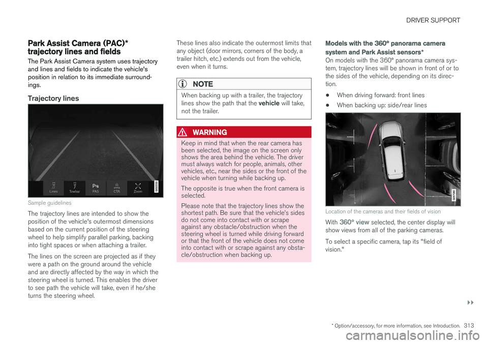
Trajectory lines
Sample guidelines
The trajectory lines are intended to show the position of the vehicle's outermost dimensionsbased on the current position of the steeringwheel to help simplify parallel parking, backinginto tight spaces or when attaching a trailer. The lines on the screen are projected as if they were a path on the ground around the vehicleand are directly affected by the way in which thesteering wheel is turned. This enables the driverto see path the vehicle will take, even if he/sheturns the steering wheel. These lines also indicate the outermost limits thatany object (door mirrors, corners of the body, atrailer hitch, etc.) extends out from the vehicle,even when it turns.
NOTE
When backing up with a trailer, the trajectory lines show the path that the
vehicle will take,
not the trailer.
WARNING
Keep in mind that when the rear camera has been selected, the image on the screen onlyshows the area behind the vehicle. The drivermust always watch for people, animals, othervehicles, etc., near the sides or the front of thevehicle when turning while backing up. The opposite is true when the front camera is selected. Please note that the trajectory lines show the shortest path. Be sure that the vehicle
Page 318 of 546
DRIVER SUPPORT
* Option/accessory, for more information, see Introduction.
316
Park Assist Camera (PAC) *
limitations
The Park Assist Camera system has certain limi- tations that the driver should be aware of.
NOTE
Bicycle carriers or other accessories mounted on the tailgate may obstruct the camera'sfield of vision.
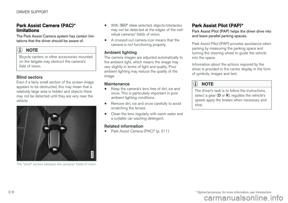
Blind sectorsEven if a fairly small section of the screen image appears to be obstructed, this may mean that arelatively large area is hidden and objects theremay not be detected until they are very near thevehicle.
The "blind" sectors between the cameras' fields of vision
• With 360° view selected, objects/obstacles
may not be detected at the edges of the indi- vidual cameras' fields of vision.
• A crossed-out camera icon means that thecamera is not functioning properly.
Ambient lightingThe camera images are adjusted automatically to the ambient light, which means the image mayvary slightly in terms of light and quality. Poorambient lighting may reduce the quality of theimage.
Maintenance
• Keep the camera's lens free of dirt, ice and snow. This is particularly important in poorambient lighting conditions.
• Remove dirt, ice and snow carefully to avoidscratching the lenses.
• Clean the lens regularly with warm water anda suitable car washing detergent.
Related information
•
Park Assist Camera (PAC)
* (p. 311)
Park Assist Pilot (PAP) *
Park Assist Pilot (PAP) helps the driver drive into and leave parallel parking spaces.
Park Assist Pilot (PAP) provides assistance when parking by measuring the parking space andturning the steering wheel to guide the vehicleinto the space. Information about the actions required by the driver is provided in the center display in the formof symbols, images and text.
NOTE
The driver's task is to follow the instructions, select a gear ( D or R), regulate the vehicle's
speed, apply the brakes when necessary and stop.
Page 321 of 546
DRIVER SUPPORT
}}
319
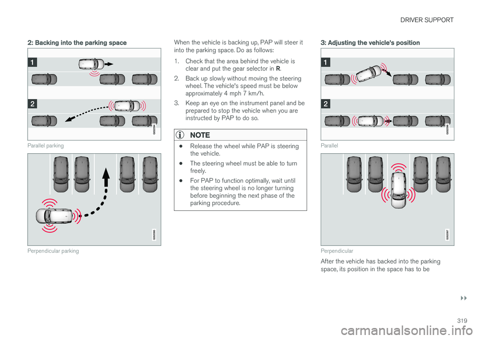
2: Backing into the parking space
Parallel parking
Perpendicular parking
When the vehicle is backing up, PAP will steer it into the parking space. Do as follows:
1. Check that the area behind the vehicle isclear and put the gear selector in R.
2. Back up slowly without moving the steering wheel. The vehicle's speed must be below approximately 4 mph 7 km/h.
3. Keep an eye on the instrument panel and be prepared to stop the vehicle when you areinstructed by PAP to do so.
NOTE
• Release the wheel while PAP is steering the vehicle.
• The steering wheel must be able to turnfreely.
• For PAP to function optimally, wait untilthe steering wheel is no longer turningbefore beginning the next phase of theparking procedure.
3: Adjusting the vehicle's position
Parallel
Perpendicular
After the vehicle has backed into the parking space, its position in the space has to be
Page 322 of 546

||
DRIVER SUPPORT
* Option/accessory, for more information, see Introduction.
320 adjusted by driving slightly forward and backing up. 1.
Put the gear selector in D, wait until the
steering wheel has turned and drive forward slowly.
2. Stop the vehicle when you are instructed by PAP to do so.
3. Put the gear selector in R, back up slowly
and stop when you are instructed by PAP todo so.
When the parking procedure is finished (this will be indicated by a text message and a graphicimage), PAP switches off automatically. If neces-sary, the driver may need to make minor adjust-ments to ensure that the vehicle is parked cor-rectly.
CAUTION
The warning distance is shorter when PAP is using the sensors than when Park Assist isusing them.
Leaving a parking spaceThis function can only be used for a vehicle that has been par-allel parked and is activated inthe center display's Functionview. 1. Tap the
Park out button in
the center display's Function view.
2. Follow the instructions provided. The proce- dure is the same as when parking the vehicle. The steering wheel may turn back slightly when the function is completed and the driver mayhave to turn the back before leaving the parkingspace. If PAP determines that the driver can leave the parking space without assistance, the functionwill deactivate before the vehicle is completelyout of the space.
Related information
• Park Assist Pilot (PAP)
* (p. 316)
• Park Assist Pilot (PAP)
* limitations (p. 320)
• Park Assist Pilot (PAP)
* symbols and mes-
sages (p. 322)
Park Assist Pilot (PAP) * limitations
The PAP function may be limited in certain situa- tions.
The PAP parking sequence is cancelledA parking sequence will be cancelled:
• if the vehicle is driven too fast (above approx. 4 mph (7 km/h)
• if the driver taps
Cancel in the center display
• if the driver moves the steering wheel with sufficient force.
• if the anti-lock brakes or Electronic StabilityControl are activated (e.g., if a wheel beginsto spin or lose traction)
In such cases, a text message will explain why the parking sequence was cancelled.
NOTE
• PAP will not function correctly if its sen- sors are obstructed by dirt, snow, etc.
• In certain situations, PAP may not be ableto measure a parking space. This couldbe due to external sources of sound (e.g.,a vehicle's horn, tires on wet asphalt,pneumatic brakes, noise from a motorcy-cle's exhaust, etc.) emitting ultrasoundusing approximately the same frequen-cies as PAP.
Page 325 of 546
DRIVER SUPPORT
}}
* Option/accessory, for more information, see Introduction.323
Adjustable steering force*
Steering force increases with the speed of the vehicle to give the driver an enhanced sense ofcontrol and stability. At low speed the vehicle iseasier to steer in order to facilitate parking, etc.
Changing the steering force levelTo change the level of steering force, see theinformation under the heading "individual" in arti-cle "Drive modes" for additional information.
NOTE
•This steering force level menu function cannot be accessed when the vehicle isin motion.
• In certain situations, the power steeringfunction may become too hot and mustbe temporarily cooled. During cooling,power steering effect will be reduced andmore force may be necessary to turn thesteering wheel and a message will bedisplayed in the instrument panel.
Related information
• Driver support systems (p. 252)
• Drive modes (p. 390)
Electronic Stability Control (ESC)
Electronic Stability Control (ESC) helps reduce wheel spin, counteract skidding and to generallyhelp improve directional stability.
A pulsating sound will be audi- ble when the system is activelyoperating and is normal. Accel-eration may also be slightlyslower than normal.
WARNING
ESC is a supplementary aid and cannot deal with all situations or road conditions. The driver is always responsible for operating the vehicle in a safe manner in accordancewith current traffic regulations.
ESC consists of the following functions: • Traction control
• Spin control
• Active Yaw Control
• Engine Drag Control
• Trailer Stability Assist
Traction controlThis function is designed to help reduce wheel spin by transferring power from a drive wheel that begins to lose traction to the wheel on the oppo-site side of the vehicle (on the same axle).
Spin controlThis function is designed to help prevent thedrive wheels from spinning while the vehicle isaccelerating.
Active Yaw ControlAt low speeds, this function helps maintain direc-tional stability by braking one or more of thewheels if the vehicle shows a tendency to skid orslide laterally.
Engine Drag Control EDCEDC helps keep the engine running if the wheelsshow a tendency to lock, e.g., when shifting downin the manual shifting mode or while using theengine's braking function on a slippery surface. Ifthe wheels were to lock, the vehicle wouldbecome more difficult to steer.
Trailer Stability Assist
*4TSA helps stabilize a vehicle that is towing atrailer when the vehicle and trailer have begun tosway. This system is automatically deactivated if the driver selects
Sport mode.
Related information
•Detachable trailer hitch (p. 368)
• Driving with a trailer (p. 367)
4
This function is included if the vehicle is equipped with a Volvo original trailer hitch.