2016 VOLVO S80 park assist
[x] Cancel search: park assistPage 240 of 380

08 Starting and driving
08
238
Transmission – general information
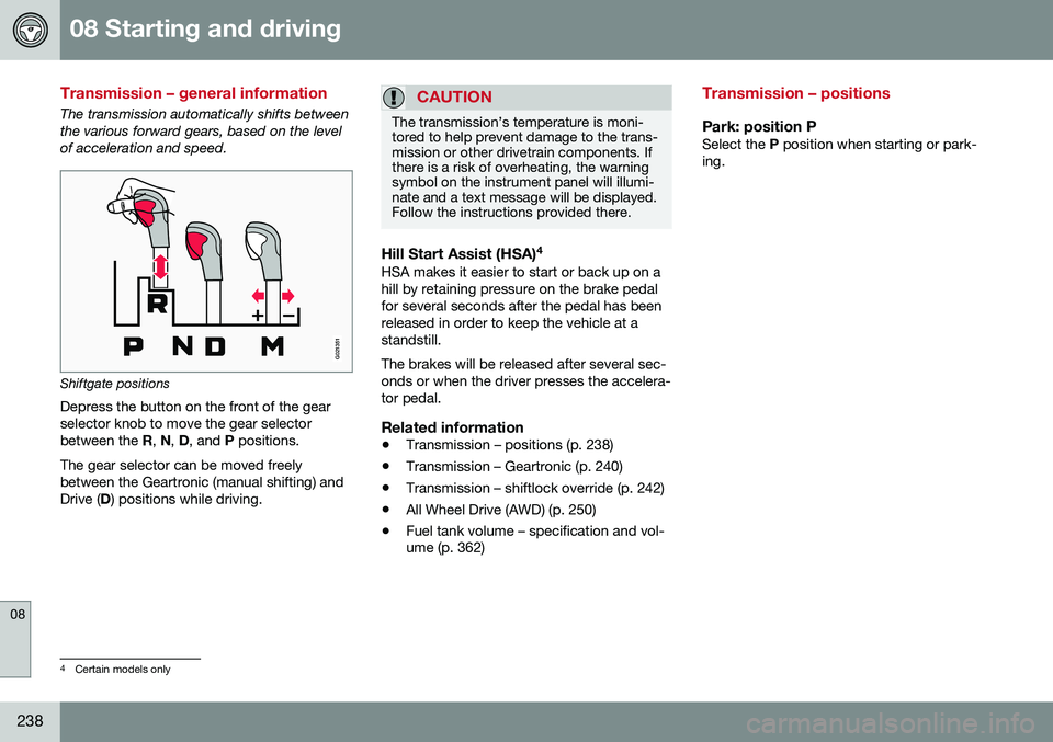
The transmission automatically shifts between the various forward gears, based on the levelof acceleration and speed.
G021351
Shiftgate positions
Depress the button on the front of the gear selector knob to move the gear selectorbetween the R, N , D , and P positions.
The gear selector can be moved freelybetween the Geartronic (manual shifting) andDrive ( D) positions while driving.
CAUTION
The transmission’s temperature is moni- tored to help prevent damage to the trans-mission or other drivetrain components. Ifthere is a risk of overheating, the warningsymbol on the instrument panel will illumi-nate and a text message will be displayed.Follow the instructions provided there.
Hill Start Assist (HSA) 4HSA makes it easier to start or back up on a hill by retaining pressure on the brake pedalfor several seconds after the pedal has beenreleased in order to keep the vehicle at astandstill. The brakes will be released after several sec- onds or when the driver presses the accelera-tor pedal.
Related information
•
Transmission – positions (p. 238)
• Transmission – Geartronic (p. 240)
• Transmission – shiftlock override (p. 242)
• All Wheel Drive (AWD) (p. 250)
• Fuel tank volume – specification and vol- ume (p. 362)
Transmission – positions
Park: position PSelect the
P position when starting or park-
ing.
4 Certain models only
Page 253 of 380

08 Starting and driving
08
}}
* Option/accessory, for more information, see Introduction.251
Brake pad inspectionOn vehicles equipped with a jack*, the condi- tion of the brake pads can be checked byraising the vehicle (see Changing a wheel –removing wheel (p. 276) for informationabout using the jack and removing a wheel)and performing a visual inspection of thebrake pads.
WARNING
• If the vehicle has been driven immedi- ately prior to a brake pad inspection,the wheel hub, brake components,etc., will be very hot. Allow time forthese components to cool before car-rying out the inspection.
• Apply the parking brake and put thegear selector in the Park (
P) position.
• Block the wheels standing on theground, use rigid wooden blocks orlarge stones.
WARNING
•Use the jack intended for the vehicle when changing a tire. For any otherjob, use stands to support the vehicle.
• The jack should be kept well-greasedand clean, and should not be dam-aged.
• Be sure the jack is on a firm, level,non-slippery surface.
• No objects should be placed betweenthe base of jack and the ground, orbetween the jack and the attachmentbar on the vehicle.
• The jack must correctly engage thejack attachment.
• Never allow any part of your body tobe extended under a vehicle suppor-ted by a jack.
Power brakes function only when the engine is running
The power brakes utilize vacuum pressure which is only created when the engine is run-ning. Never let the vehicle roll to a stop withthe engine switched off. If the power brakes are not working, consid- erably higher pressure will be required on thebrake pedal to compensate for the lack ofpower assistance. This can happen for exam-ple when towing your vehicle or if the engineis switched off when the vehicle is rolling. Thebrake pedal feels harder than usual.
Water on brake discs and brake pads affects braking
Driving in rain and slush or passing through an automatic car wash can cause water tocollect on the brake discs and pads. This willcause a delay in braking effect when thepedal is depressed. To avoid such a delaywhen the brakes are needed, depress thepedal occasionally when driving through rain,slush, etc. This will remove the water from thebrakes. Check that brake application feelsnormal. This should also be done after wash-ing or starting in very damp or cold weather.
Severe strain on the brake systemThe brakes will be subject to severe strainwhen driving in mountains or hilly areas, orwhen towing a trailer. Vehicle speed is usuallyslower, which means that the cooling of thebrakes is less efficient than when driving onlevel roads. To reduce the strain on thebrakes, shift into a lower gear and let theengine help with the braking. Do not forgetthat if you are towing a trailer, the brakes willbe subjected to a greater than normal load.
Cleaning the brake discsCoatings of dirt and water on the brake discsmay result in delayed brake function. Thisdelay is minimized by cleaning the brake lin-ings. Cleaning the brake pads is advisable in wet weather, prior to long-term parking, and afterthe vehicle has been washed. Do this by
Page 254 of 380

||
08 Starting and driving
08
252
braking gently for a short period while the vehicle is moving.
Related information
•Parking brake – general information (p. 254)
• Emergency Brake Assistance (EBA)(p. 253)
• Brakes – general (p. 250)
• Anti-lock braking system (ABS) (p. 252)
Brakes – symbols
Symbols in the instrument panel
SymbolSpecification
Steady glow – Check the brake fluid level. If the level is low, fillwith brake fluid and check forthe cause of the brake fluidloss.
Automatic function check: steady glow for two secondswhen the engine is started.
WARNING
If and come on at the
same time and the brake level is below the MIN mark in the reservoir or if a brake sys-
tem-related message is shown in the infor-mation display: DO NOT DRIVE . Have the
vehicle towed to a trained and qualifiedVolvo service technician and have thebrake system inspected.
Related information
• Brakes – general (p. 250)
• Parking brake – general information (p. 254)
Anti-lock braking system (ABS)
The ABS system helps to improve vehicle control (stopping and steering) during severebraking conditions by limiting brake lockup. When the system "senses" impending lockup, braking pressure is automatically modulatedin order to help prevent lockup that couldlead to a skid. The system performs a brief self-diagnostic test when the engine has been started anddriver releases the brake pedal. Another auto-matic test may be performed when the vehi-cle first reaches a speed of approximately6 mph (10 km/h). The brake pedal will pulsateseveral times and a sound may be audiblefrom the ABS control module, which is nor-mal.
Related information
• Parking brake – general information (p. 254)
• Emergency Brake Assistance (EBA)(p. 253)
• Brakes – general (p. 250)
Page 255 of 380

08 Starting and driving
08
253
Brake lights
The brake lights come on automatically when the brakes are applied.
Adaptive brake lightsThe adaptive brake lights activate in the event of sudden braking or if the ABS system isactivated. This function causes an additionaltaillight on each side of the vehicle to illumi-nate to help alert vehicles traveling behind. The adaptive brake lights activate if: •The ABS system activates for more than approximately a half second
• In the event of sudden braking while thevehicle is moving at speeds aboveapproximately 6 mph (10 km/h).
When the vehicle has come to a stop, the brake lights and additional taillights remain onfor as long as the brake pedal is depressed oruntil braking force on the vehicle is reduced.
Related information
• Brakes – general (p. 250)
• Parking brake – general information (p. 254)
Emergency Brake Assistance (EBA)
EBA is designed to provide full brake effect immediately in the event of sudden, hardbraking.
Emergency Brake AssistanceThe EBA system is activated by the speedwith which the brake pedal is depressed. When the EBA system is activated, the brake pedal will go down and pressure in the brakesystem immediately increases to the maxi-mum level. Maintain full pressure on thebrake pedal in order to utilize the systemcompletely. EBA is automatically deactivatedwhen the brake pedal is released.
NOTE
• When the EBA system is activated, the brake pedal will go down and pressurein the brake system immediatelyincreases to the maximum level. Youmust maintain full pressure on thebrake pedal in order to utilize the sys-tem completely. There will be no brak-ing effect if the pedal is released. EBAis automatically deactivated when thebrake pedal is released.
• When the vehicle has been parked forsome time, the brake pedal may sinkmore than usual when the engine isstarted. This is normal and the pedalwill return to its usual position when itis released.
Related information
•
Parking brake – general information (p. 254)
• Brakes – general (p. 250)
• Anti-lock braking system (ABS) (p. 252)
Page 304 of 380

||
09 Wheels and tires
09
302
WARNING
The bottle is equipped with a catch to keep it securely in place and help preventsealing compound leakage. Once in place,the bottle cannot be unscrewed. This mustbe done by a trained and qualified Volvoservice technician.
5. Remove the valve cap from the tire’sinflation valve and screw the tire sealing system’s hose connector onto the valveas tightly as possible by hand.
6. Connect the electrical wire to the nearest 12-volt socket in the vehicle.
NOTE
Be sure that none of the other 12-volt sockets is being used while the compres-sor is in operation.
7. Start the vehicle’s engine.
WARNING
The vehicle´s engine should be running when the tire sealing system is used toavoid battery drain. Therefore, be sure thevehicle is parked in a well ventilated place,or outdoors, before using the system.
8. Start the tire sealing system’s compres-sor by pressing the on/off switch to posi- tion I.
WARNING
• Never stand next to the tire being infla- ted when the compressor is in opera-tion.
• If cracks, bubbles, etc. form on the tire,switch off the compressor immediately.
• If there is visible damage to the sidewallor the rim, the tire cannot be repaired.The vehicle should not be driven if thisoccurs. Contact a towing service orVolvo On Call Roadside Assistance ifapplicable.
NOTE
The air pressure gauge will temporarily show an increase in pressure to approxi-mately 88 psi (6 bar) while the sealingcompound is being pumped into the tire.The pressure should return to a normallevel after approximately 30 seconds.
9. Within seven minutes, inflate the tire to
between 22—44 psi (1.8—3.0 bar). Switch off the compressor briefly to get aclear reading from the pressure gauge.
Page 342 of 380

||
10 Maintenance and servicing
10
340* Option/accessory, for more information, see Introduction.
PosFunctionA
Controls in left rear passeng- er's door20
Keyless drive*20
Power driver's seat*20
Power front passenger's seat*20
-
Infotainment system display5
Infotainment system: amplifier, SiriusXM ™ satellite radio*10
Sensus control module15
Bluetooth hands-free system5
-
Power moonroof* Courtesy lighting, climate sys- tem sensor5
12-volt sockets in tunnel con- sole15
Heated rear seat* (passenger's side)15
Heated rear seat* (driver's side)15
PosFunctionA
-
Heated front passenger's seat*15
Heated driver's seat*15
Park assist*5
All Wheel Drive* control mod- ule15
Active chassis system*10
Positions: fusebox B
PosFunctionA
-
-
Front courtesy lighting, driv- er's door power window con-trols, power seat(s)*,7.5
Instrument panel5
Adaptive cruise control/colli- sion warning*10
Courtesy lighting, rain sen- sor*, HomeLInk ®
Wireless
Control System*7.5
PosFunctionA
Steering wheel module7.5
Cental locking: fuel filler door10
-
Windshield washers15
Trunk open10
Electrical folding rear seat outboard head restraints*10
Fuel pump20
Climate system control panel5
-
Alarm, On-board diagnostic system5
Satellite radio *, audio system amplifier10
Airbag system, occupant weight sensor10
Collision warning system*5
Accelerator pedal sensor, auto-dim mirror function,heated rear seats*7.5
Page 367 of 380

11 Specifications
11
* Option/accessory, for more information, see Introduction.365
Symbols in the main instrument panel
Warning symbols in the instrument panel
SymbolDescriptionSee
Low oil pressure(p. 68)
Parking brake A(p. 68)
SRS airbags(p. 68)
Seat belt reminder(p. 68)
Generator not charg- ing(p. 68)
Fault in the brake sys- tem(p. 68)
Warning symbol(p. 68)
A
The symbol is Park only on models with the optional digital
instrument panel.
Related information
• Information displays – indicator symbols (p. 66)
• Information displays – warning symbols(p. 68)
• Information display – messages (p. 107)
Indicator symbols
The following tables list the most common warning and indicator lights and symbols anda reference to where more detailed informa-tion can be found.
: The red warning symbol illuminates to
indicate a problem related to safety and/or drivability. A message will also appear in themain instruments panel's display.
: The information symbol illuminates and
a text message is displayed to provide the driver with necessary information about oneof the vehicle's systems.
Indicator symbols in the instrument
panel
SymbolDescriptionSee
Fault in the Active Bending Light(ABL)*system(p. 66)
Malfunction indicator light(p. 66)
Anti-lock brake sys- tem (ABS)(p. 66)
Rear fog lights on(p. 66)
SymbolDescriptionSee
Stability system, Hill Descent Control,Trailer StabilityAssist*(p. 66)
Tire pressure moni- toring sensor (TPMS)(p. 66)
Low fuel level(p. 66)
Information symbol, see text in informa-tion display(p. 66)
High beam indicator(p. 66)
Left turn signal indi- cator(p. 66)
Right turn signal indi- cator(p. 66)
Stability system , Sport mode(p. 163)
Related information
• Information displays – indicator symbols (p. 66)
• Information displays – warning symbols(p. 68)
• Information display – messages (p. 107)
Page 369 of 380

11 Specifications
11
* Option/accessory, for more information, see Introduction.367
Information symbols – ceiling console
The following tables list the most common warning and indicator lights and symbols anda reference to where more detailed informa-tion can be found.
: The red warning symbol illuminates to
indicate a problem related to safety and/or drivability. A message will also appear in themain instruments panel's display.
: The information symbol illuminates and
a text message is displayed to provide the driver with necessary information about oneof the vehicle's systems.
SymbolDescriptionSee
Seat belt reminder(p. 30)
Occupant Weight Sen- sor(p. 36)
Related information
• Information displays – indicator symbols (p. 66)
• Information displays – warning symbols(p. 68)
• Information display – messages (p. 107)
Information symbols – center console
The following tables list the most common warning and indicator lights and symbols anda reference to where more detailed informa-tion can be found.
: The red warning symbol illuminates to
indicate a problem related to safety and/or drivability. A message will also appear in themain instruments panel's display.
: The information symbol illuminates and
a text message is displayed to provide the driver with necessary information about oneof the vehicle's systems.
SymbolDescriptionSee
Audio filesSensus Info- tainment sup-plement
CD folderSensus Info- tainment sup-plement
Video filesSensus Info- tainment sup-plement
Bluetooth- connected cellphoneSensus Info- tainment sup-plement
SymbolDescriptionSee
Bluetooth TM
hands-freeSensus Info- tainment sup-plement
HD radioSensus Info- tainment sup-plement
Park Assist*(p. 219)
Related information
• Information displays – indicator symbols (p. 66)
• Information displays – warning symbols(p. 68)
• Information display – messages (p. 107)