2016 VOLVO S80 transmission
[x] Cancel search: transmissionPage 8 of 380

Contents
6* Option/accessory, for more information, see Introduction.
07
Collision warning* – limitations............... 202
The camera’s limitations......................... 204
Collision warning – troubleshooting........ 205Collision warning – symbols and mes-
sages....................................................... 207
Driver Alert System................................. 209
Driver Alert Control (DAC) – introduction 209
Driver Alert Control (DAC) – operation.... 210
Driver Alert Control (DAC) – function...... 210
Driver Alert Control (DAC) – limitations... 211Driver Alert Control (DAC) – symbols and
messages................................................ 212 Lane Departure Warning (LDW) – intro-
duction.................................................... 214 Lane Departure Warning (LDW) – opera-
tion.......................................................... 214 Lane Departure Warning (LDW) - limita-
tions........................................................ 216 Lane Departure Warning (LDW) – sym-
bols and messages................................. 217
Park assist – introduction....................... 219
Park assist – function.............................. 219
Park assist – operation........................... 221
Park assist – limitations.......................... 222
Park assist – troubleshooting.................. 223
07
Rear Park Assist Camera (PAC) – intro-
duction.................................................... 223 Rear Park Assist Camera (PAC) – func-
tion.......................................................... 224 Rear Park Assist Camera (PAC) – opera-
tion.......................................................... 224 Rear Park Assist Camera (PAC) – guiding
and marker lines...................................... 225 Rear Park Assist Camera (PAC) – limita-
tions........................................................ 227
BLIS* – introduction................................ 227
BLIS* – function...................................... 228
BLIS* – operation.................................... 229
BLIS* – limitations................................... 229
BLIS* – messages................................... 230
08
08 Starting and driving
Starting the engine.................................. 233
Switching off the engine......................... 235Engine Remote Start (ERS)* – introduc-
tion.......................................................... 235 Engine Remote Start (ERS)* – starting the
engine..................................................... 236 Engine Remote Start (ERS)* – switching
off the engine.......................................... 236
Jump starting.......................................... 237
Transmission – general information........ 238
Transmission – positions........................ 238
Transmission – Geartronic...................... 240
Transmission – shiftlock override........... 242
Start/Stop – Hill Start Assist (HSA)......... 243
Start/Stop – introduction........................ 243
Start/Stop – function............................... 243
Start/Stop – Auto-stop exceptions......... 244
Start/Stop – Auto-start exceptions......... 245
Start/Stop – settings............................... 246
Start/Stop – symbols and messages...... 247
ECO*....................................................... 248
All Wheel Drive (AWD)............................. 250
Brakes – general..................................... 250
Brakes – symbols ................................... 252
Page 10 of 380
Contents
8
10
10 Maintenance and servicing
Maintenance – introduction.................... 307
Maintenance – owner maintenance........ 308
Maintenance – hoisting........................... 309
Onboard Diagnostic System................... 310
Booking service and repairs .................. 310
Maintenance – opening/closing hood..... 312
Engine compartment – overview............ 313
Engine compartment – engine oil........... 314
Engine compartment – coolant............... 316
Engine compartment – brake fluid.......... 317Engine compartment – power steering
fluid......................................................... 318
Bulbs – introduction................................ 319
Bulbs – headlight housing....................... 320
Bulbs – cover.......................................... 321
Bulbs – low beam, Halogen.................... 321
Bulbs – high beam, Halogen................... 322
Bulbs – extra high beam......................... 322
Bulbs – front turn signals........................ 323
Bulbs – front side marker lights.............. 324
Bulbs – taillight housing.......................... 324
Bulbs – license plate lighting.................. 325
Bulbs – trunk lighting.............................. 326
Bulbs – vanity mirror lighting.................. 326
10
Bulbs – specifications............................. 326
Wiper blades – service position.............. 327
Wiper blades – windshield...................... 328
Engine compartment – washer fluid....... 329
Battery – symbols................................... 330
Battery – handling................................... 330
Battery – maintenance............................ 331
Battery – changing.................................. 332
Fuses – introduction............................... 333
Fuses – engine compartment................. 335
Fuses – glove compartment................... 339
Fuses – cargo area/trunk........................ 342Fuses – engine compartment cold zone
(Start/Stop only)...................................... 343
Washing the car...................................... 345
Automatic car wash................................ 346
Polishing and waxing.............................. 346
Cleaning the interior................................ 347
Touching up paintwork........................... 349
11
11 Specifications
Label information.................................... 352
Dimensions............................................. 355
Weights................................................... 357
Engine specifications.............................. 358
Oil specifications..................................... 359
Oil volume............................................... 360
Coolant – specification and volume........ 361Transmission oil – specification and vol-
umes....................................................... 361
Brake fluid – specification and volume... 361
Power steering – specification................ 362Fuel tank volume – specification and vol-
ume......................................................... 362 Air conditioning – specification and vol-
ume......................................................... 362
Battery specifications............................. 363
Symbols – general information............... 364
Warning symbols.................................... 364
Indicator symbols.................................... 365
Information symbols............................... 366
Information symbols – ceiling console.... 367
Information symbols – center console.... 367
Page 69 of 380

03 Instruments and controls
03
}}
* Option/accessory, for more information, see Introduction.67
Malfunction Indicator LightAs you drive, a computer called On-Board Diagnostics II (OBDII) monitors your vehicle'sengine, transmission, electrical and emissionsystems. The malfunction indicator light will illuminate if the computer senses a condition that poten-tially may need correcting. When this hap-pens, please have your vehicle checked by atrained and qualified Volvo service technicianas soon as possible. A malfunction indicator light may have many causes. Sometimes, you may not notice achange in your car's behavior. Even so, anuncorrected condition could hurt fuel econ-omy, emission controls, and drivability.Extended driving without correcting the causecould even damage other components inyour vehicle. This light may illuminate if the fuel filler cap is not closed tightly or if the engine was runningwhile the vehicle was refueled.
Anti-lock Brake System (ABS)If the warning light comes on, there may be a malfunction in the ABS system (the standardbraking system will still function). Check thesystem by:
1. Stopping in a safe place and switching off
the ignition.
2. Restart the engine. 3. If the warning light goes off, no further
action is required.
If the indicator light remains on, the vehicle should be driven to a trained and qualifiedVolvo service technician for inspection, seeBrakes – general (p. 250) for additional infor-mation.
Rear fog lightsThis symbol indicates that the rear fog lights are on.
Stability systemThis indicator symbol flashes when the stabil- ity system is actively working to stabilize thevehicle, see Stability system – introduction(p. 162) for more detailed information.
Stability system - Sport modeThis symbol illuminates to indicate that the stability system's Sport mode has been acti-
vated to help provide maximum tractive force,for example when driving with snow chains,or driving in deep snow or loose sand.
Low fuel levelWhen this light comes on, the vehicle should be refueled as soon as possible. See Refuel-ing – fuel requirements (p. 261) for informa-tion about fuel and refueling.
Information symbolThe information symbol lights up and a text message is displayed to provide the driverwith necessary information about one of thevehicle's systems. The message can beerased and the symbol can be turned off by pressing the
OK button (see Information dis-
play – menu controls (p. 106) for information)or this will take place automatically after ashort time (the length of time varies, depend-ing on the function affected). The information symbol may also illuminate together with other symbols.
High beam indicatorThis symbol illuminates when the high beam headlights are on, or if the high beam flashfunction is used.
Left turn signal indicator
Right turn signal indicator
NOTE
• Both turn signal indicators will flash when the hazard warning flashers areused.
• If either of these indicators flash fasterthan normal, the direction indicatorsare not functioning properly.
Tire pressure monitoring system (TPMS)*
This symbol illuminates to indicate that tire pressure in one or more tires is low, see TirePressure Monitoring System (TPMS) – generalinformation (p. 291) for detailed information.
Eco* function onThe symbol will illuminate when the Eco func- tion is activated.
Page 82 of 380

03 Instruments and controls
03
80
Rear seats – folding backrest
The rear seat head restraints and backrests can be folded down. The center headrestraint can be raised/lowered according tothe passenger's height.
Folding down the rear seat backrests
The rear seat backrests are split and can be folded down together or separately1. Pull the release control handle(s).
2. Fold the backrest forward. Adjust the center seat head restraint if necessary.
NOTE
When the backrests are folded down, move the outboard head restraints forwardslightly so that they do not catch on theseat cushion.
CAUTION
To help avoid damage to the upholstery, there should be no objects on the rear seatand the seat belt should not be buckledwhen the backrest is folded down.
WARNING
•Keep vehicle doors and trunk locked and keep keys out of a child’s reach.Unsupervised children could lockthemselves in an open trunk and riskinjury. Children should be taught not toplay in vehicles.
• On hot days, the temperature in thetrunk or vehicle interior can rise veryquickly. Exposure of people to thesehigh temperatures for even a shortperiod of time can cause heat-relatedinjury or death. Small children are par-ticularly at risk.
WARNING
•
When one or more sections of the backrest is returned to the uprightposition, check that it is properlylocked in place by pushing and pullingit.
• Return the outboard head restraints tothe upright position.
• Long loads should always be securelyanchored to help avoid injury in theevent of a sudden stop.
• Always turn the engine off and applythe parking brake when loading/unloading the vehicle.
• Place the transmission in the Park (
P)
position to help prevent inadvertentmovement of the gear selector.
• On hot days, the temperature in thevehicle interior can rise very quickly.Exposure of people to these high tem-peratures for even a short period oftime can cause heat-related injury ordeath. Small children are particularly atrisk.
Related information
•
Front seats (p. 74)
• Front seats – power seat (p. 75)
• Rear seats – head restraints (p. 78)
Page 83 of 380
03 Instruments and controls
03
* Option/accessory, for more information, see Introduction.81
Steering wheel
The steering wheel can be adjusted to various positions and has controls for the horn, cruisecontrol*, menus, the infotainment system and Bluetooth
®-connected cell phone.
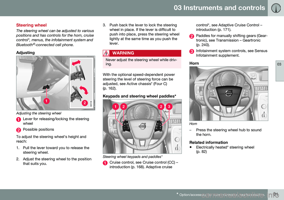
Adjusting
G021138
Adjusting the steering wheel
Lever for releasing/locking the steering wheel
Possible positions
To adjust the steering wheel's height and reach:
1. Pull the lever toward you to release the steering wheel.
2. Adjust the steering wheel to the position that suits you. 3. Push back the lever to lock the steering
wheel in place. If the lever is difficult to push into place, press the steering wheellightly at the same time as you push thelever.
WARNING
Never adjust the steering wheel while driv- ing.
With the optional speed-dependent power steering the level of steering force can beadjusted, see Active chassis* (Four C)(p. 162).
Keypads and steering wheel paddles*
Steering wheel keypads and paddles*
Cruise control, see Cruise control (CC) – introduction (p. 168). Adaptive cruise control*, see Adaptive Cruise Control –introduction (p. 171).
Paddles for manually shifting gears (Gear- tronic), see Transmission – Geartronic(p. 240).
Infotainment system controls, see Sensus Infotainment supplement.
Horn
Horn
–Press the steering wheel hub to sound the horn.
Related information
•
Electrically heated* steering wheel (p. 82)
Page 99 of 380
03 Instruments and controls
03
* Option/accessory, for more information, see Introduction.97
Related information
• Interior rearview mirror (p. 98)
• Heated windshield*, rear window and door mirror defrosters (p. 98)
• Power door mirrors – automatic tilting/retraction (p. 97)
Power door mirrors – automatic tilting/retraction
The control on the driver's door is used to adjust the position of the door mirrors.
Automatically tilting the door mirrors
when parking
The door mirrors can tilt down automaticallyto help give the driver a better view along thesides of the vehicle, for example when paral-lel parking. When the transmission is nolonger in reverse, the mirrors will automati-cally return to their original position. This function can be activated/deactivated in MY CAR under
SettingsCar settings
Side mirror settingsIn reverse gear tilt
left mirror
or In reverse gear tilt right
mirror. See My Car – introduction (p. 70) for
information about the MY CAR menu system.
Automatic retraction when lockingWhen the vehicle is locked/unlocked with the remote key the door mirrors are automaticallyretracted/extended. The function can be activated/deactivated in MY CAR under
SettingsCar settings
Side mirror settingsRetract side mirrors
when locking. See My Car – introduction
(p. 70) for a description of the menu system.
Resetting to neutralMirrors that have been moved out of position by an external force must be electrically resetto the neutral position for electric retracting/extending to work. • Retract the mirrors with the
L and R but-
tons.
• Fold them out again with the
L and R but-
tons.
The mirrors are now reset in neutral position.
Related information
• Interior rearview mirror (p. 98)
• Heated windshield*, rear window and door mirror defrosters (p. 98)
Page 105 of 380
03 Instruments and controls
03
}}
* Option/accessory, for more information, see Introduction.103
Retain the original transmitter of the RF device you are programming for use in othervehicles as well as for future HomeLink pro-gramming. It is also suggested that upon thesale of the vehicle, the programmed Home-Link buttons be erased for security purposes.Refer to “Resetting HomeLink Buttons” in HomeLink
®
Wireless Control System* – pro-
gramming (p. 103).
Using HomeLinkTo operate, simply press and hold the pro- grammed HomeLink button until the traineddevice begins to operate (this may take sev-eral seconds). Activation will now occur forthe trained device (i.e., garage door opener,gate operator, security system, entry doorlock, home/office lighting, etc.). For conven-ience, the hand-held transmitter of the devicemay also be used at any time. In the eventthat there are still programming difficulties orquestions, contact HomeLink at:www.homelink.com/www.youtube.com/HomeLinkGentex or by phoning the hotline at1–800–355–3515.
NOTE
If the ignition is switched off, HomeLink will function for 30 minutes after the driv-er's door has been opened.
HomeLink ®
Wireless Control System*
– programming
The HomeLink Wireless Control System pro- vides a convenient way to replace up to threehand-held radio-frequency (RF) transmittersused to activate devices such as gate opera-tors, garage door openers, entry door locks,security systems, even home lighting. Addi-tional information can be found on the Inter-net atwww.homelink.com/www.youtube.com/HomeLinkGentex or by phoning the hotline at1–800–355–3515.
NOTE
Some vehicles may require the ignition to be switched on or be in the “accessories”position for programming and/or operationof HomeLink. It is also recommended thata new battery be placed in the hand-heldtransmitter of the device being pro-grammed to HomeLink for quicker trainingand accurate transmission of the radio-fre-quency signal. The HomeLink buttonsmust be reset first. When this has beencompleted, Homelink is in learning modeso that you can perform programming.
1. Position the end of your hand-held trans- mitter 1–3 inches (5–14 cm) away from the HomeLink button you wish to pro-gram while keeping the indicator light inview. 2. Simultaneously press and hold both the
chosen HomeLink and hand-held trans-mitter buttons until the HomeLink indica-tor light changes from a slow to a rapidlyblinking light. Now you may release boththe HomeLink and hand-held transmitterbuttons.
NOTE
Some devices may require you to replace this Programming Step 2 with proceduresnoted in the “Gate Operator / CanadianProgramming” section. If the HomeLinkindicator light does not change to a rapidlyblinking light after performing these steps,contact HomeLink at www.homelink.com/www.youtube.com/HomeLinkGentex or byphoning the hotline at 1–800–355–3515.
Page 106 of 380
||
03 Instruments and controls
03
104
3. Firmly press, hold for five seconds and
release the programmed HomeLink but-
ton up to two separate times to activate the door. If the door does not activate,press and hold the just-trained HomeLinkbutton and observe the indicator light.
• If the indicator light
stays on con-
stantly, programming is complete and your device should activate when the HomeLink button is pressed andreleased.
• If the indicator light blinks
rapidly for
two seconds and then turns to aconstant light continue with “Pro- gramming” steps 4-6 to complete the
programming of a rolling code equip- ped device (most commonly a garagedoor opener).
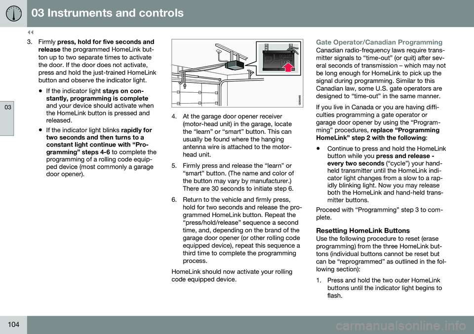
4. At the garage door opener receiver
(motor-head unit) in the garage, locate the “learn” or “smart” button. This canusually be found where the hangingantenna wire is attached to the motor-head unit.
5. Firmly press and release the “learn” or “smart” button. (The name and color ofthe button may vary by manufacturer.)There are 30 seconds to initiate step 6.
6. Return to the vehicle and firmly press, hold for two seconds and release the pro-grammed HomeLink button. Repeat the“press/hold/release” sequence a secondtime, and, depending on the brand of thegarage door opener (or other rolling codeequipped device), repeat this sequence athird time to complete the programmingprocess.
HomeLink should now activate your rollingcode equipped device.
Gate Operator/Canadian ProgrammingCanadian radio-frequency laws require trans- mitter signals to “time-out” (or quit) after sev-eral seconds of transmission – which may notbe long enough for HomeLink to pick up thesignal during programming. Similar to thisCanadian law, some U.S. gate operators aredesigned to “time-out” in the same manner. If you live in Canada or you are having diffi- culties programming a gate operator orgarage door opener by using the “Program-ming” procedures, replace “Programming
HomeLink” step 2 with the following :
• Continue to press and hold the HomeLink button while you
press and release -
every two seconds (“cycle”) your hand-
held transmitter until the HomeLink indi-cator light changes from a slow to a rap-idly blinking light. Now you may releaseboth the HomeLink and hand-held trans-mitter buttons.
Proceed with “Programming” step 3 to com- plete.
Resetting HomeLink ButtonsUse the following procedure to reset (eraseprogramming) from the three HomeLink but-tons (individual buttons cannot be reset butcan be “reprogrammed” as outlined in the fol-lowing section):
1. Press and hold the two outer HomeLink buttons until the indicator light begins to flash.