2016 VOLVO S80 park assist
[x] Cancel search: park assistPage 223 of 380

07 Driver support
07
}}
221
Front park assist
G021424
The distance monitored in front of the vehicle is approximately 2.5 ft (0.8 m). The audiblesignal comes from the audio system's frontspeakers. It may not be possible to combine auxiliary headlights and front park assist since theselights could trigger the system's sensors.
NOTE
Front park assist is deactivated when the parking brake is applied and or when thegear selector is in the P position.
Related information
• Park assist – introduction (p. 219)
• Park assist – limitations (p. 222)
• Park assist – operation (p. 221)
• Park assist – troubleshooting (p. 223) •
Rear Park Assist Camera (PAC) – function (p. 224)
Park assist – operation
Function
Park assist button
The system is activated automatically when the vehicle is started. The indicator light in thebutton in the center console illuminates whenthe system is on.
• The front park assist system is active from the time the engine is started untilthe vehicle exceeds a speed of approxi-mately 6 mph (10 km/h). It is also activewhen the vehicle is backing up.
• Rear park assist is active when the engineis running and reverse gear has beenselected.
Page 224 of 380

||
07 Driver support
07
222
Activating/deactivatingThe system is activated automatically when the vehicle is started.
–Press the Park assist button on the center console to temporarily deactivate the sys-tem(s).
> The indicator light in the button will goout when the system has been deacti- vated.
Park assist will be automatically reactivatedthe next time the engine is started, or if thebutton is pressed (the indicator light in thebutton will illuminate).
NOTE
Park assist is disengaged automatically when the parking brake is applied.
Related information
• Park assist – introduction (p. 219)
• Park assist – limitations (p. 222)
• Park assist – function (p. 219)
• Park assist – troubleshooting (p. 223)
• Rear Park Assist Camera (PAC) – function (p. 224)
Park assist – limitations
Cleaning the sensorsThe sensors must be cleaned regularly to ensure that they work properly. Clean themwith water and a suitable car washing deter-gent.
Location of the front sensors
G021425
Location of the rear sensors. Ice and snow covering the sensors may cause incorrect warning signals.
NOTE
If the sensors are obstructed by e.g., dirt, snow, or ice, this could result in falsewarning signals from the park assist sys-tem.
Related information
•
Park assist – introduction (p. 219)
• Park assist – function (p. 219)
• Park assist – operation (p. 221)
• Park assist – troubleshooting (p. 223)
• Rear Park Assist Camera (PAC) – function (p. 224)
Page 225 of 380

07 Driver support
07
223
Park assist – troubleshooting
Faults in the systemIf the information symbol illuminates andPark assist syst Service required is shown
on the information display, this indicates that the system is not functioning properly andhas been disengaged. Consult a trained andqualified Volvo service technician.
CAUTION
In certain circumstances, the park assist system may give unexpected warning sig-nals that can be caused by external soundsources that use the same ultrasound fre-quencies as the system. This may includesuch things as the horns of other vehicles,wet tires on asphalt, pneumatic brakes,motorcycle exhaust pipes, etc. This doesnot indicate a fault in the system.
Related information
• Park assist – introduction (p. 219)
• Park assist – limitations (p. 222)
• Park assist – function (p. 219)
• Park assist – operation (p. 221)
• Rear Park Assist Camera (PAC) – function (p. 224)
Rear Park Assist Camera (PAC) – introduction
The Park Assist Camera is designed to pro- vide the driver with a view of the area behindthe vehicle when backing up.
IntroductionPAC uses the display in the center console toshow the area behind the car while you arebacking up. PAC also shows guiding lines in the on- screen image to indicate the direction that thevehicle will take as it moves rearward, whichhelps simplify parallel parking, backing into atight space or when attaching a trailer to thevehicle. The images of vehicles in this section are generic and may not depict your specificmodel.
NOTE
A trailer hitch whose wiring is integrated with the vehicle's electrical system will beincluded in the measurement of the availa-ble space behind the vehicle.
WARNING
• PAC is designed to be a supplemen- tary aid when parking the vehicle. It isnot, however, intended to replace thedriver’s attention and judgment.
• The camera has blind spots where itcannot detect objects or peoplebehind the vehicle.
• Pay particular attention to people oranimals that are close to the vehicle.
• Objects seen on the screen may becloser than they appear to be.
Related information
•
Rear Park Assist Camera (PAC) – opera- tion (p. 224)
• Rear Park Assist Camera (PAC) – limita-tions (p. 227)
Page 226 of 380

07 Driver support
07
224
Rear Park Assist Camera (PAC) – function
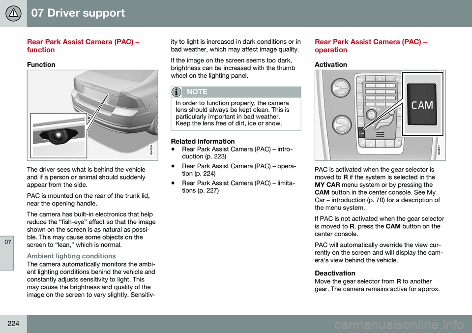
Function
The driver sees what is behind the vehicle and if a person or animal should suddenlyappear from the side. PAC is mounted on the rear of the trunk lid, near the opening handle. The camera has built-in electronics that help reduce the “fish-eye” effect so that the imageshown on the screen is as natural as possi-ble. This may cause some objects on thescreen to “lean,” which is normal.
Ambient lighting conditionsThe camera automatically monitors the ambi- ent lighting conditions behind the vehicle andconstantly adjusts sensitivity to light. Thismay cause the brightness and quality of theimage on the screen to vary slightly. Sensitiv-ity to light is increased in dark conditions or inbad weather, which may affect image quality. If the image on the screen seems too dark, brightness can be increased with the thumbwheel on the lighting panel.
NOTE
In order to function properly, the camera lens should always be kept clean. This isparticularly important in bad weather.Keep the lens free of dirt, ice or snow.
Related information
•
Rear Park Assist Camera (PAC) – intro- duction (p. 223)
• Rear Park Assist Camera (PAC) – opera-tion (p. 224)
• Rear Park Assist Camera (PAC) – limita-tions (p. 227)
Rear Park Assist Camera (PAC) – operation
Activation
PAC is activated when the gear selector is moved to
R if the system is selected in the
MY CAR menu system or by pressing the
CAM button in the center console. See My
Car – introduction (p. 70) for a description ofthe menu system. If PAC is not activated when the gear selector is moved to R, press the CAM button on the
center console. PAC will automatically override the view cur- rently on the screen and will display the cam-era's view behind the vehicle.
DeactivationMove the gear selector from R to another
gear. The camera remains active for approx.
Page 227 of 380

07 Driver support
07
}}
* Option/accessory, for more information, see Introduction.225
5 seconds after the gear selector has been moved from
R or until the vehicle's forward
speed exceeds 6 mph/10 km/h(21 mph/35 km/h in reverse). The screen willthen revert to the view that was displayedbefore R was selected.
NOTE
If any button on the center console control panel is pressed, the camera image willdisappear from the display. Pressing CAM
will return the camera image to the display.
SettingsBy default, PAC is set to activate when the gear selector is moved to R
To change PAC settings when a camera viewis displayed:
1. Press OK/MENU when a camera view is
on the screen. A menu will be displayed.
2. Turn TUNE to scroll to the desired set-
ting.
3. Press OK/MENU to make the setting and
exit the menu by pressing EXIT.
Summary
•Pressing
CAM will activate the camera
even if the gear selector is not in Reverse.
• If there are two cameras installed on the vehicle*, turn
TUNE or press CAM to tog-
gle between the cameras.
Related information
• Park assist – introduction (p. 219)
• Park assist – function (p. 219)
• Park assist – troubleshooting (p. 223)
• Park assist – limitations (p. 222)
• Rear Park Assist Camera (PAC) – intro-duction (p. 223)
Rear Park Assist Camera (PAC) – guiding and marker lines
Guiding lines
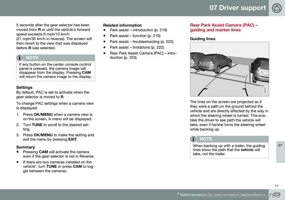
The lines on the screen are projected as if they were a path on the ground behind thevehicle and are directly affected by the way inwhich the steering wheel is turned. This ena-bles the driver to see path the vehicle willtake, even if he/she turns the steering wheelwhile backing up.
NOTE
When backing up with a trailer, the guiding lines show the path that the
vehicle will
take, not the trailer.
Page 228 of 380

||
07 Driver support
07
226
WARNING
Keep in mind that the image on the screen only shows the area behind the vehicle.The driver must always watch for people,animals, other vehicles, etc., near the sidesof the vehicle when turning while backingup.
Marker lines
The PAC system's lines
An area approx. 1 ft (30 cm) behind the vehicle
The line marking the unobstructed area behind the vehicle
The red line (1) frames an area approx. 1 ft(30 cm) behind the vehicle from the bumper. The yellow horizontal line (2) frames an area up to approx. 5 feet (1.5 m) behind thebumper. These lines also indicate the outermost limitsthat any object (door mirrors, corners of thebody, etc.) extends out from the vehicle, evenwhen it turns.
Vehicles equipped with Park Assist
Colored markers (one for each sensor) indicate distance If the vehicle is equipped with the optional Park Assist system (see Park assist – intro-duction (p. 219)), the distance to an objectwill be indicated more exactly and coloredmarkers in the display indicate which of thesensor(s) has detected the object.
ColorDistance to object
Green2.5–5 ft (0.8–1.5 m)
Yellow1.3–2.5 ft (0.4–0.8 m)
Red0–1.3 ft (0–0.4 m)
Related information
•
Rear Park Assist Camera (PAC) – opera- tion (p. 224)
• Rear Park Assist Camera (PAC) – limita-tions (p. 227)
Page 229 of 380

07 Driver support
07
}}
* Option/accessory, for more information, see Introduction.227
Rear Park Assist Camera (PAC) – limitations
LimitationsEven if a fairly small section of the screen image appears to be obstructed, this maymean that a relatively large area behind thevehicle is hidden and objects there may notbe detected until they are very near the vehi-cle.
NOTE
Bicycle carriers or other accessories mounted on the trunk may obstruct thecamera's field of view.
Keep in mind
• Keep the camera's lens free of dirt, ice and snow. Remove ice and snow care-fully to avoid scratching the lens.
• Clean the lens regularly with warm waterand a suitable car washing detergent.
Related information
•Rear Park Assist Camera (PAC) – intro-duction (p. 223)
• Rear Park Assist Camera (PAC) – opera-tion (p. 224)
• Park assist – introduction (p. 219)
BLIS* – introduction
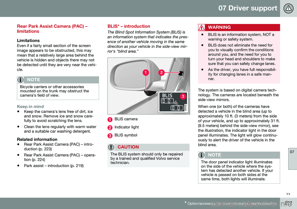
The Blind Spot Information System (BLIS) is an information system that indicates the pres-ence of another vehicle moving in the samedirection as your vehicle in the side-view mir-ror's "blind area."
G021426
BLIS camera
Indicator light
BLIS symbol
CAUTION
The BLIS system should only be repaired by a trained and qualified Volvo servicetechnician.
WARNING
• BLIS is an information system, NOT a warning or safety system.
• BLIS does not eliminate the need foryou to visually confirm the conditionsaround you, and the need for you toturn your head and shoulders to makesure that you can safely change lanes.
• As the driver, you have full responsibil-ity for changing lanes in a safe man-ner.
The system is based on digital camera tech- nology. The cameras are located beneath theside-view mirrors. When one (or both) of the cameras have detected a vehicle in the blind area (up toapproximately 10 ft. (3 meters) from the sideof your vehicle, and up to approximately 31 ft.(9.5 meters) behind the side-view mirror), seethe illustration, the indicator light in the doorpanel illuminates. The light will glow continu-ously to alert the driver of the vehicle in theblind area.
NOTE
The door panel indicator light illuminates on the side of the vehicle where the sys-tem has detected another vehicle. If yourvehicle is passed on both sides at thesame time, both lights will illuminate.
Page 239 of 380

08 Starting and driving
08
237
Jump starting
Follow these instructions to jump start your vehicle's dead battery or to jump start anothervehicle's dead battery using your vehicle.
G021347
Connecting the jumper cablesIf the 12-volt auxiliary battery to be used is in another vehicle, check that the vehicles arenot touching to prevent premature comple-tion of a circuit. Be sure to follow jump star-ting instructions provided for the other vehi-cle. To jump start your vehicle:
1. Switch off the ignition (set the ignition to mode 0, see Ignition modes (p. 73)).
2. First connect the red jumper cable to the auxiliary battery's positive (+) terminal (1). 3. Fold back the cover over the positive (+)
terminal on your vehicle's battery (2), marked with a "+" sign, located under afolding cover.
4. Connect the black jumper cable to the auxiliary battery's negative (–) terminal (3)and to the ground point in your vehicle'sengine compartment (right engine mountat the top, on the outer screw) (4).
5. Start the engine in the assisting vehicle, then start the engine in the vehicle withdead battery.
6. After the engine has started, first remove the negative (–) terminal jumper cable(black). Then remove the positive (+) ter-minal jumper cable (red).
WARNING
PROPOSITION 65 WARNING! Battery posts, terminals, and related accessories contain lead and lead com-pounds, chemicals known to the state ofCalifornia to cause cancer and reproduc-tive harm. Wash hands after handling.
CAUTION
Connect the jumper cables carefully to avoid short circuits with other componentsin the engine compartment.
WARNING
•Do not connect the jumper cable to any part of the fuel system or to anymoving parts. Avoid touching hotmanifolds.
• Batteries generate hydrogen gas,which is flammable and explosive.
• Battery fluid contains sulfuric acid. Donot allow battery fluid to contact eyes,skin, fabrics or painted surfaces. Ifcontact occurs, flush the affected areaimmediately with water. Obtain medi-cal help immediately if eyes are affec-ted.
• Never expose the battery to openflame or electric spark.
• Do not smoke near the battery.
• Failure to follow the instructions forjump starting can lead to injury.
Related information
•
Starting the engine (p. 233)