2016 SUBARU IMPREZA ESP
[x] Cancel search: ESPPage 191 of 594
Instruments and controls/Multi function display
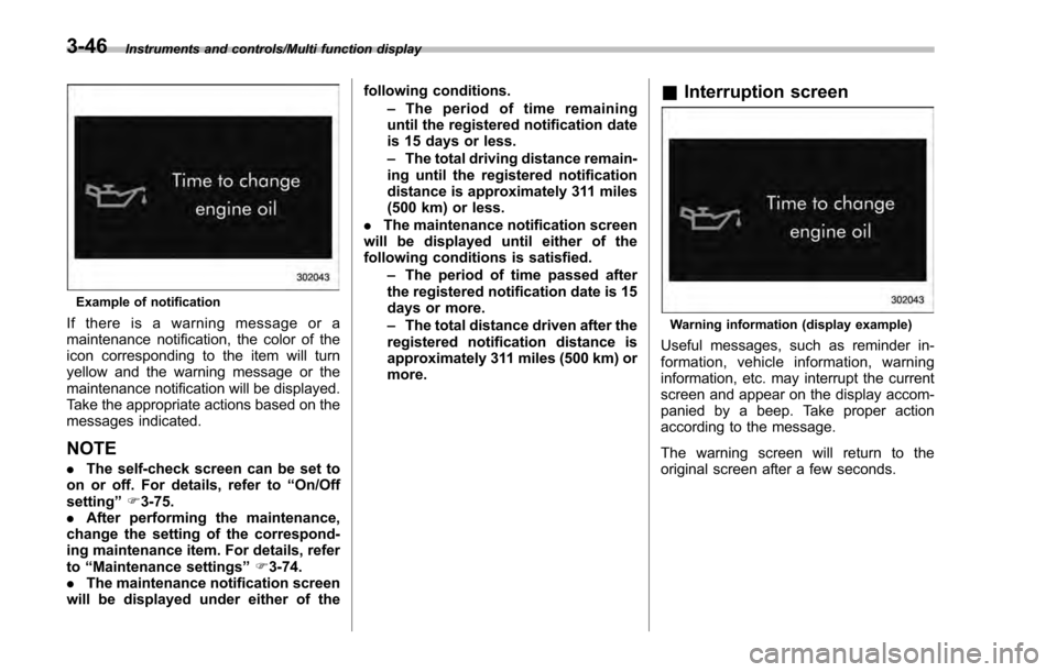
Example of notification
If there is a warning message or a
maintenance notification, the color of the
icon corresponding to the item will turn
yellow and the warning message or the
maintenance notification will be displayed.
Take the appropriate actions based on the
messages indicated.
NOTE
.The self-check screen can be set to
on or off. For details, refer to “On/Off
setting ”F 3-75.
. After performing the maintenance,
change the setting of the correspond-
ing maintenance item. For details, refer
to “Maintenance settings ”F 3-74.
. The maintenance notification screen
will be displayed under either of the following conditions.
–The period of time remaining
until the registered notification date
is 15 days or less.
– The total driving distance remain-
ing until the registered notification
distance is approximately 311 miles
(500 km) or less.
. The maintenance notification screen
will be displayed until either of the
following conditions is satisfied.
–The period of time passed after
the registered notification date is 15
days or more.
– The total distance driven after the
registered notification distance is
approximately 311 miles (500 km) or
more.
& Interruption screen
Warning information (display example)
Useful messages, such as reminder in-
formation, vehicle information, warning
information, etc. may interrupt the current
screen and appear on the display accom-
panied by a beep. Take proper action
according to the message.
The warning screen will return to the
original screen after a few seconds.
3-46
Page 193 of 594

Instruments and controls/Multi function display
temperature has increased to 418F
(5 8C) or higher.
! Top display
One of the following items can be dis-
played on the top display.
. Average fuel consumption correspond-
ing to the driving distance of each trip
meter
. Current fuel consumption (This may
not be displayed when driving at a low
speed.)
. Driving range on remaining fuel
For details about the setting of the top
display, refer to “Top display setting ”F 3-
66.
NOTE
The driving range on the remaining fuel
is calculated using the average fuel
consumption of the last 19 miles (30
km) driven. This value may be different
from the values calculated using the
average fuel consumption correspond-
ing to the driving distance of each trip
meter or the current fuel consumption. !
Clock
The clock can be displayed in either 12-
hour display or 24-hour display. For details
about the setting, refer to “Current date
and time setting ”F 3-57.
NOTE
If the vehicle battery is disconnected,
the clock shown in the information bar
will be reset. Set the time again after
the vehicle battery is connected. For
details about the setting, refer to “To p
display setting ”F 3-66. !
Fuel consumption screen
1) Average fuel consumption corresponding
to the driving distance of each trip meter
2) Current fuel consumption
3) Driving range on remaining fuel
The displayed location can be custo-
mized. For details, refer to “Fuel consump-
tion screen setting ”F 3-67.
3-48
Page 194 of 594
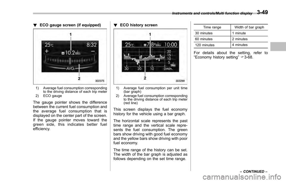
!ECO gauge screen (if equipped)
1) Average fuel consumption corresponding
to the driving distance of each trip meter
2) ECO gauge
The gauge pointer shows the difference
between the current fuel consumption and
the average fuel consumption that is
displayed on the center part of the screen.
If the gauge pointer moves toward the
green side, this indicates better fuel
efficiency. !
ECO history screen
1) Average fuel consumption per unit time
(bar graph)
2) Average fuel consumption corresponding to the driving distance of each trip meter
(red line)
This screen displays the fuel economy
history for the vehicle using a bar graph.
The horizontal scale represents the past
time range and the vertical scale repre-
sents the fuel consumption. The green
bars show driving with good fuel economy
and the yellow bars show driving with poor
fuel economy.
The time range of the history can be set.
The width of the bar graph is adjusted as
follows depending on the set time range.
Time range Width of bar graph
30 minutes 1 minute
60 minutes 2 minutes
120 minutes 4 minutes
For details about the setting, refer to
“
Economy history setting ”F 3-68.
Instruments and controls/Multi function display
–CONTINUED –3-49
Page 240 of 594
&Steering responsive fog
lights system (models with
EyeSight system)
The steering responsive fog lights system
automatically turns the front fog light on
and off based on the steering angle and
vehicle speed when entering a curve or
driving on curved roads. The system is
intended to help prevent accidents by
enabling better visibility of curves ahead
and early recognition of any disabled
vehicles or other obstacles.
The front fog light on the inside of a curve
will turn on if all of the following conditions
are met.
. The light control switch is in the “
”
position
. The light control switch is in the
“AUTO ”position and the low beam head-
lights turn on automatically
. The fog light switch is in the “
”
position
. The low beam mode is selected
. The select lever is in a position other
than the “R”position
. The steering response fog lights sys-
tem has not been deactivated
. The operating conditions such as the
steering angle and vehicle speed are met
The front fog lights on both sides will turn on as usual if all of the following conditions
are met.
.
The light control switch is in either of
the following conditions.
–in the “
”position
– in the “AUTO ”position and the low
beam headlights turn on automatically
. The fog light switch is in the “
”
position
. The low beam mode is selected !
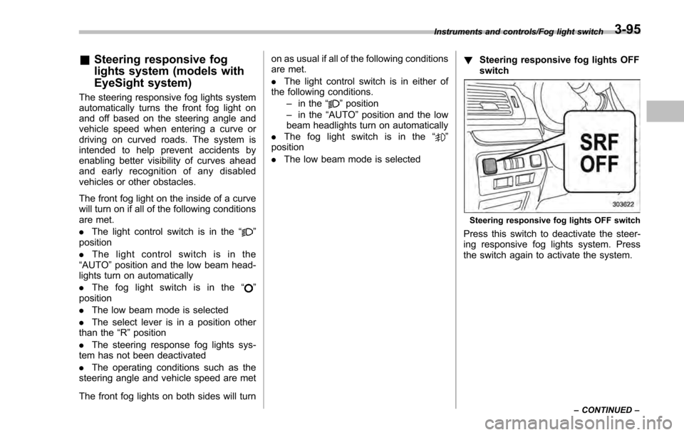
Steering responsive fog lights OFF
switch
Steering responsive fog lights OFF switch
Press this switch to deactivate the steer-
ing responsive fog lights system. Press
the switch again to activate the system.
Instruments and controls/Fog light switch
–CONTINUED –3-95
Page 241 of 594
Instruments and controls/Wiper and washer
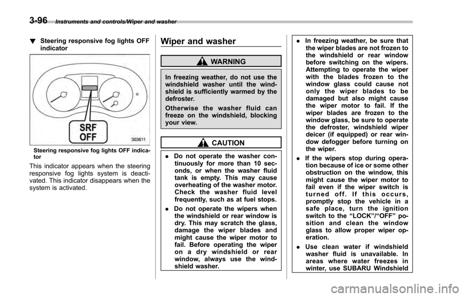
!Steering responsive fog lights OFF
indicator
Steering responsive fog lights OFF indica-
tor
This indicator appears when the steering
responsive fog lights system is deacti-
vated. This indicator disappears when the
system is activated.
Wiper and washer
WARNING
In freezing weather, do not use the
windshield washer until the wind-
shield is sufficiently warmed by the
defroster.
Otherwise the washer fluid can
freeze on the windshield, blocking
your view.
CAUTION
.Do not operate the washer con-
tinuously for more than 10 sec-
onds, or when the washer fluid
tank is empty. This may cause
overheating of the washer motor.
Check the washer fluid level
frequently, such as at fuel stops.
. Do not operate the wipers when
the windshield or rear window is
dry. This may scratch the glass,
damage the wiper blades and
might cause the wiper motor to
fail. Before operating the wiper
on a dry windshield or rear
window, always use the wind-
shield washer. .
In freezing weather, be sure that
the wiper blades are not frozen to
the windshield or rear window
before switching on the wipers.
Attempting to operate the wiper
with the blades frozen to the
window glass could cause not
only the wiper blades to be
damaged but also might cause
the wiper motor to fail. If the
wiper blades are frozen to the
window glass, be sure to operate
the defroster, windshield wiper
deicer (if equipped) or rear win-
dow defogger before turning on
the wiper.
. If the wipers stop during opera-
tion because of ice or some other
obstruction on the window, this
might cause the wiper motor to
fail even if the wiper switch is
turned off. If this occurs,
promptly stop the vehicle in a
safe place, turn the ignition
switch to the “LOCK”/“OFF ”po-
sition and clean the window
glass to allow proper wiper op-
eration.
. Use clean water if windshield
washer fluid is unavailable. In
areas where water freezes in
winter, use SUBARU Windshield
3-96
Page 244 of 594
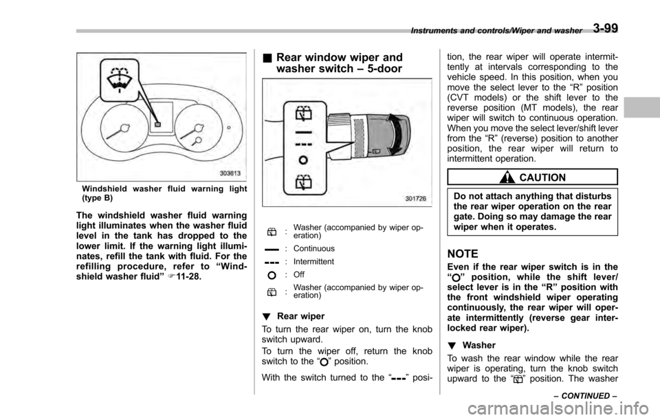
Windshield washer fluid warning light
(type B)
The windshield washer fluid warning
light illuminates when the washer fluid
level in the tank has dropped to the
lower limit. If the warning light illumi-
nates, refill the tank with fluid. For the
refilling procedure, refer to“Wind-
shield washer fluid ”F 11-28.
& Rear window wiper and
washer switch –5-door
: Washer (accompanied by wiper op-
eration)
: Continuous
: Intermittent
: Off
:Washer (accompanied by wiper op-
eration)
!
Rear wiper
To turn the rear wiper on, turn the knob
switch upward.
To turn the wiper off, return the knob
switch to the “
”position.
With the switch turned to the “
”posi- tion, the rear wiper will operate intermit-
tently at intervals corresponding to the
vehicle speed. In this position, when you
move the select lever to the
“R”position
(CVT models) or the shift lever to the
reverse position (MT models), the rear
wiper will switch to continuous operation.
When you move the select lever/shift lever
from the “R”(reverse) position to another
position, the rear wiper will return to
intermittent operation.
CAUTION
Do not attach anything that disturbs
the rear wiper operation on the rear
gate. Doing so may damage the rear
wiper when it operates.
NOTE
Even if the rear wiper switch is in the
“” position, while the shift lever/
select lever is in the “R”position with
the front windshield wiper operating
continuously, the rear wiper will oper-
ate intermittently (reverse gear inter-
locked rear wiper).
! Washer
To wash the rear window while the rear
wiper is operating, turn the knob switch
upward to the “
”position. The washer
Instruments and controls/Wiper and washer
–CONTINUED –3-99
Page 252 of 594
6. When the indicator light flashes slowly
and then rapidly after several seconds,
release both buttons.
7. Plug the motor of the entrance gate/
garage door opener to the outlet.
8. Test your entrance gate/garage door
opener by pressing the programmed
HomeLink
®button.
! Operating the HomeLink
®Wire-
less Control System
Once programmed, the HomeLink
®Wire-
less Control System can be used to
remote-control the devices to which its
buttons are programmed. To activate a
device, simply press the appropriate but-
ton. The indicator light illuminates, indicat-
ing that the signal is being transmitted.
!Programming other devices
To program other devices such as door
locks, home lighting and security systems,
contact HomeLink
®at www.homelink.com
or call 1-800-355-3515.
! Reprogramming a single
HomeLink
®button
1. Press and hold the HomeLink
®button
you wish to reprogram. DO NOT release
the button until step 4 has been com-
pleted.
2. When the HomeLink
®indicator light begins to flash slowly (after approximately
20 seconds), position the hand-held trans-
mitter of the device between 1 to 3 inches
(25 to 76 mm) away from the HomeLink
®button you wish to program.
3. Press and hold the hand-held trans-
mitter button. The HomeLink
®indicator
light will flash, first slowly and then rapidly.
4. When the indicator light begins to flash
rapidly, release both buttons.
The programming for the previous device
is now erased and the new device can be
operated by pressing the HomeLink
®button.
!Erasing HomeLink
®button mem-
ory
NOTE
. Performing this procedure erases
the memory of all the preprogrammed
buttons simultaneously. The memory
of individual buttons cannot be erased.
. It is recommended that upon the
sale of the vehicle, the memory of all
programmed HomeLink
®buttons be
erased for security purposes.
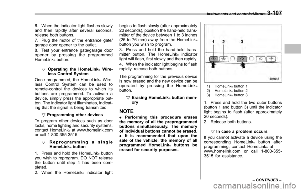
1) HomeLink®button 1
2) HomeLink®button 2
3) HomeLink®button 3
1. Press and hold the two outer buttons
(button 1 and button 3) until the indicator
light begins to flash (after approximately
20 seconds).
2. Release both buttons.
!In case a problem occurs
If you cannot activate a device using the
corresponding HomeLink
®button after
programming, contact HomeLink®at
www.homelink.com or call 1-800-355-
3515 for assistance.
Instruments and controls/Mirrors
–CONTINUED –3-107
Page 278 of 594

&Tips for operating the audio/
visual system
CAUTION
To avoid damage to the audio/visual
system:
. Be careful not to spill beverages
over the audio/visual system.
. Do not put anything other than an
appropriate disc into the disc
slot.
NOTE
The use of a cell phone inside or near
the vehicle may cause a noise from the
speakers of the audio/visual system
which you are listening to. However,
this does not indicate a malfunction.
! Radio
Usually, a problem with radio reception
does not mean there is a problem with the
radio —it is just the normal result of
conditions outside the vehicle.
For example, nearby buildings and terrain
can interfere with FM reception. Power
lines or phone wires can interfere with AM
signals. And of course, radio signals have
a limited range. The farther the vehicle is from a station, the weaker its signal will
be. In addition, reception conditions
change constantly as the vehicle moves.
Here, some common reception problems
that probably do not indicate a problem
with the radio are described.
!FM
Fading and drifting stations: Generally, the
effective range of FM is about 25 miles (40
km). Once outside this range, you may
notice fading and drifting, which increase
with the distance from the radio transmit-
ter. They are often accompanied by
distortion.
Multi-path: FM signals are reflective,
making it possible for 2 signals to reach
the vehicle’ s antenna at the same time. If
this happens, the signals will cancel each
other out, causing a momentary flutter or
loss of reception.
Static and fluttering: These occur when
signals are blocked by buildings, trees or
other large objects. Increasing the bass
level may reduce static and fluttering.
Station swapping: If the FM signal being
listened to is interrupted or weakened, and
there is another strong station nearby on
the FM band, the radio may tune in the
second station until the original signal can
be picked up again. !
AM
Fading: AM broadcasts are reflected by
the upper atmosphere —especially at
night. These reflected signals can inter-
fere with those received directly from the
radio station, causing the radio station to
sound alternately strong and weak.
Station interference: When a reflected
signal and a signal received directly from
a radio station are very nearly the same
frequency, they can interfere with each
other, making it difficult to hear the broad-
cast.
Static: AM is easily affected by external
sources of electrical noise, such as high
tension power lines, lightening or electrical
motors. This results in static.
!SiriusXM (if equipped)
. Cargo loaded on the roof luggage
carrier, especially metal objects, may
adversely affect the reception of SiriusXM
Satellite Radio.
. Alternation or modifications carried out
without appropriate authorization may in-
validate the user ’s right to operate the
equipment.
Audio/Audio set
–CONTINUED –5-7