2016 SUBARU IMPREZA ESP
[x] Cancel search: ESPPage 412 of 594
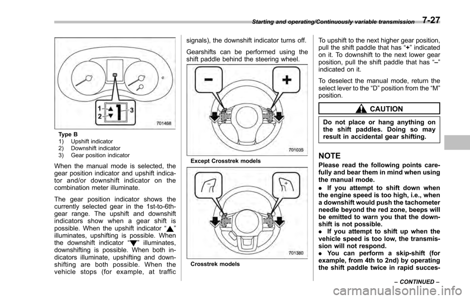
Type B
1) Upshift indicator
2) Downshift indicator
3) Gear position indicator
When the manual mode is selected, the
gear position indicator and upshift indica-
tor and/or downshift indicator on the
combination meter illuminate.
The gear position indicator shows the
currently selected gear in the 1st-to-6th-
gear range. The upshift and downshift
indicators show when a gear shift is
possible. When the upshift indicator“
”
illuminates, upshifting is possible. When
the downshift indicator “
”illuminates,
downshifting is possible. When both in-
dicators illuminate, upshifting and down-
shifting are both possible. When the
vehicle stops (for example, at traffic signals), the downshift indicator turns off.
Gearshifts can be performed using the
shift paddle behind the steering wheel.
Except Crosstrek models
Crosstrek models
To upshift to the next higher gear position,
pull the shift paddle that has
“+”indicated
on it. To downshift to the next lower gear
position, pull the shift paddle that has “–”
indicated on it.
To deselect the manual mode, return the
select lever to the “D”position from the “M”
position.
CAUTION
Do not place or hang anything on
the shift paddles. Doing so may
result in accidental gear shifting.
NOTE
Please read the following points care-
fully and bear them in mind when using
the manual mode.
. If you attempt to shift down when
the engine speed is too high, i.e., when
a downshift would push the tachometer
needle beyond the red zone, beeps will
be emitted to warn you that the down-
shift is not possible.
. If you attempt to shift up when the
vehicle speed is too low, the transmis-
sion will not respond.
. You can perform a skip-shift (for
example, from 4th to 2nd) by operating
the shift paddle twice in rapid succes-
Starting and operating/Continuously variable transmission
–CONTINUED –7-27
Page 420 of 594

face; since having Vehicle Dy-
namics Control is no guarantee
that full vehicle control will be
maintained at all times and under
all conditions, its activation
should be seen as a sign that
the speed of the vehicle should
be reduced considerably.
. Whenever suspension compo-
nents, steering components, or
an axle are removed from a
vehicle, have an inspection of
that system performed by an
authorized SUBARU dealer.
. The following precautions should
be observed in order to ensure
that the Vehicle Dynamics Con-
trol system is operating properly:
– All four wheels should be
fitted with tires of the same
size, type, and brand. Further-
more, the amount of wear
should be the same for all
four tires.
– Keep the tire pressure at the
proper level as shown on the
vehicle placard attached to
the driver ’s side door pillar.
– Use only the specified tem-
porary spare tire to replace a
flat tire. With a temporary spare tire, the effectiveness of
the Vehicle Dynamics Control
system is reduced and this
should be taken into account
when driving the vehicle in
such a condition.
. If non-matching tires are used,
the Vehicle Dynamics Control
system may not operate cor-
rectly.
. The Vehicle Dynamics Control
system helps prevent unstable
vehicle motion such as skidding
using control of the brakes and
engine power. Do not turn off the
Vehicle Dynamics Control sys-
tem unless it is absolutely ne-
cessary. If you must turn off the
Vehicle Dynamics Control sys-
tem, drive very carefully accord-
ing to the road surface condi-
tions.
& System features
In the event of wheelspin and/or skidding
on a slippery road surface and/or during
cornering and/or an evasive maneuver,
the Vehicle Dynamics Control system
adjusts the engine ’s output and the
wheels’ respective braking forces to help maintain traction and directional control.
.
Traction Control Function
The traction control function is designed to
prevent spinning of the driving wheels on
slippery road surfaces, thereby helping to
maintain traction and directional control.
Activation of this function is shown by
steady illumination of the Vehicle Dy-
namics Control operation indicator light.
. Skid Suppression Function
The skid suppression function is designed
to help maintain directional stability by
suppressing the wheels’ tendency to slide
sideways during steering operations. Acti-
vation of this function is shown by flashing
of the Vehicle Dynamics Control operation
indicator light.
NOTE
. The Vehicle Dynamics Control sys-
tem may be considered normal when
the following conditions occur.
–Slight twitching of the brake
pedal is felt.
– The vehicle or steering wheel
shakes to a small degree.
– An operating sound from the
engine compartment is heard
briefly when starting the engine
and when driving off after starting
the engine.
Starting and operating/Vehicle Dynamics Control system
–CONTINUED –7-35
Page 424 of 594
pressure threshold, the low tire
pressure warning light should
turn off a few minutes later.
If this light still illuminates while
driving after adjusting the tire
pressure, a tire may have signifi-
cant damage and a fast leak that
causes the tire to lose air rapidly.
If you have a flat tire, replace it
with a spare tire as soon as
possible.
. When a spare tire is mounted or a
wheel rim is replaced without the
original pressure sensor/trans-
mitter being transferred, the low
tire pressure warning light will
illuminate steadily after blinking
for approximately one minute.
This indicates the TPMS is un-
able to monitor all four road
wheels. Contact your SUBARU
dealer as soon as possible for
tire and sensor replacement and/
or system resetting.
. When a tire is repaired with liquid
sealant, the tire pressure warning
valve and transmitter may not
operate properly. If a liquid sea-
lant is used, contact your nearest
SUBARU dealer or other qualified
service shop as soon as possi-
ble. Make sure to replace the tire pressure warning valve and
transmitter when replacing the
tire. You may reuse the wheel if
there is no damage to it and if the
sealant residue is properly
cleaned off. Do not inject any tire
liquid or aerosol tire sealant into
the tires, as this may cause a
malfunction of the tire pressure
sensors. If the light illuminates
steadily after blinking for ap-
proximately one minute,
promptly contact a SUBARU
dealer to have the system in-
spected.
CAUTION
Do not place metal film or any metal
parts in the trunk. This may cause
poor reception of the signals from
the tire pressure sensors, and the
tire pressure monitoring system will
not function properly.
FCC ID: CWTWD1U781
NOTE
This device complies with part 15 of the
FCC Rules. Operation is subject to the
following two conditions: (1) This de-
vice may not cause harmful interfer- ence, and (2) this device must accept
any interference received, including
interference that may cause undesired
operation.
FCC CAUTION
Changes or modifications not ex-
pressly approved by the party respon-
sible for compliance could void the
user
’s authority to operate the equip-
ment.
Starting and operating/Tire pressure monitoring system (TPMS) (U.S. –spec. models)7-39
Page 435 of 594
Starting and operating/BSD/RCTA (5–door models —if equipped)
! To decrease the speed (by brake
pedal)
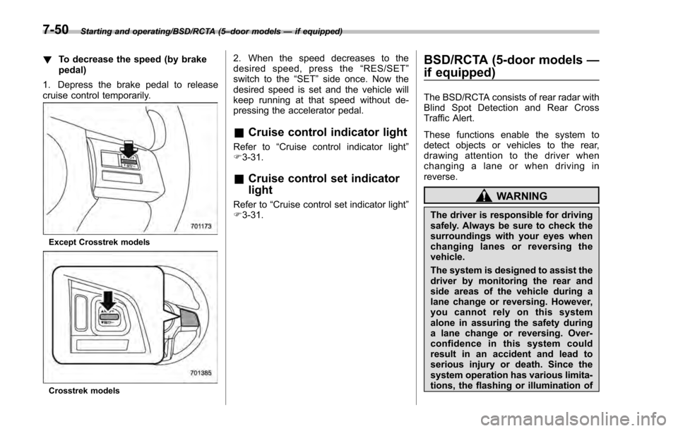
1. Depress the brake pedal to release
cruise control temporarily.
Except Crosstrek models
Crosstrek models
2. When the speed decreases to the
desired speed, press the “RES/SET ”
switch to the “SET”side once. Now the
desired speed is set and the vehicle will
keep running at that speed without de-
pressing the accelerator pedal.
& Cruise control indicator light
Refer to “Cruise control indicator light ”
F 3-31.
& Cruise control set indicator
light
Refer to “Cruise control set indicator light ”
F 3-31.
BSD/RCTA (5-door models —
if equipped)
The BSD/RCTA consists of rear radar with
Blind Spot Detection and Rear Cross
Traffic Alert.
These functions enable the system to
detect objects or vehicles to the rear,
drawing attention to the driver when
changing a lane or when driving in
reverse.
WARNING
The driver is responsible for driving
safely. Always be sure to check the
surroundings with your eyes when
changing lanes or reversing the
vehicle.
The system is designed to assist the
driver by monitoring the rear and
side areas of the vehicle during a
lane change or reversing. However,
you cannot rely on this system
alone in assuring the safety during
a lane change or reversing. Over-
confidence in this system could
result in an accident and lead to
serious injury or death. Since the
system operation has various limita-
tions, the flashing or illumination of
7-50
Page 436 of 594
the BSD/RCTA approach indicator
light may be delayed or it may not
operate at all even when a vehicle is
present in a neighboring lane or
approaching from either side.
The driver is responsible for paying
attention to the rear and side areas
of the vehicle.
&System features
BSD/RCTA consists of the following func-
tions.
. To detect a vehicle in a blind spot on an
adjacent lane or a vehicle approaching at
high speed while driving the vehicle (Blind
Spot Detection)
. To detect a vehicle approaching from
the right or left while reversing the vehicle
(Rear Cross Traffic Alert)
The system uses radar sensors for the
above functions.
NOTE
The BSD/RCTA radar sensor has been
certified by the radio wave related laws
of the U.S. When driving in other
countries, certification of the country
where the vehicle is driven must be
obtained. For certification in the U.S.,
refer to “Certification for the BSD/ RCTA
”F 7-57.
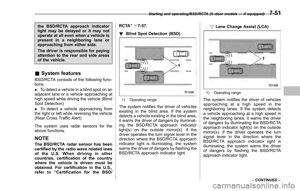
! Blind Spot Detection (BSD)
1) Operating range
The system notifies the driver of vehicles
existing in the blind area. If the system
detects a vehicle existing in the blind area,
it warns the driver of dangers by illuminat-
ing the BSD/RCTA approach indicator
light(s) on the outside mirror(s). If the
driver operates the turn signal lever in the
direction where the BSD/RCTA approach
indicator light is illuminating, the system
warns the driver of dangers by flashing the
BSD/RCTA approach indicator light. !
Lane Change Assist (LCA)
1) Operating range
The system notifies the driver of vehicles
approaching at a high speed in the
neighboring lanes. If the system detects
a vehicle approaching at a high speed in
the neighboring lanes, it warns the driver
of dangers by illuminating the BSD/RCTA
approach indicator light(s) on the outside
mirror(s). If the driver operates the turn
signal lever in the direction where the
BSD/RCTA approach indicator light is
illuminating, the system warns the driver
of dangers by flashing the BSD/RCTA
approach indicator light.
Starting and operating/BSD/RCTA (5 –door models —if equipped)
–CONTINUED –7-51
Page 440 of 594
activated by pressing the BSD/RCTA
OFF switch
–Immediately after the shift lever/
select lever is shifted to the “R ”
position
– When extremely heavy cargo is
loaded in the trunk or cargo area
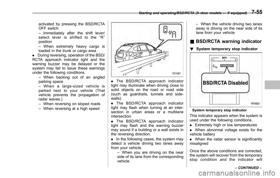
. During reversing, operation of the BSD/
RCTA approach indicator light and the
warning buzzer may be delayed or the
system may fail to issue these warnings
under the following conditions.
–When backing out of an angled
parking space
– When a large-sized vehicle is
parked next to your vehicle (That
vehicle prevents the propagation of
radar waves.)
– When reversing on sloped roads
– When reversing at a high speed
. The BSD/RCTA approach indicator
light may illuminate when driving close to
solid objects on the road or road side
(such as guardrails, tunnels and side-
walls).
. The BSD/RCTA approach indicator
light may flash when turning at an inter-
section in urban areas or a multilane
intersection.
. The BSD/RCTA approach indicator
light may flash and the warning buzzer
may sound if a building or a wall exists in
the reversing direction.
. In the following cases, the system may
detect a vehicle driving two lanes away
from your vehicle.
–When you are driving on the near
side of its lane from the corresponding
vehicle –
When the vehicle driving two lanes
away is driving on the near side of its
lane from your vehicle
& BSD/RCTA warning indicator
! System temporary stop indicator
System temporary stop indicator
This indicator appears when the system is
used under the following conditions.
.Extremely high or low temperatures
. When abnormal voltage exists for the
vehicle battery
. When the radar sensor is significantly
misaligned
Once the above conditions are corrected,
the system will recover from the temporary
stop condition and the indicator will
Starting and operating/BSD/RCTA (5 –door models —if equipped)
–CONTINUED –7-55
Page 450 of 594

sudden stops or jolts, unsecured cargo
could be thrown around in the vehicle and
cause injury. Do not pile heavy loads on
the roof. Those loads raise the vehicle’s
center of gravity and make it more prone
to tip over.
. Never equip your vehicle with tires
larger than those specified in this manual.
! During driving
General precautions:
. Drive carefully. Do not take unneces-
sary risks by driving in dangerous areas or
over rough terrain.
. Slow down and employ extra caution at
all times. When driving off-road, you will
not have the benefit of marked traffic
lanes, banked curves, traffic signs and
the like.
. Do not drive across steep slopes.
Instead, drive either straight up or straight
down the slopes. A vehicle can much
more easily tip over sideways than it can
end over end. Avoid driving straight up or
down slopes that are too steep.
. Avoid sharp turning maneuvers, espe-
cially at higher speeds.
. Do not grip the inside or spokes of the
steering wheel. A bad bump could jerk the
wheel and injure your hands. Instead,
drive with your fingers and thumbs on
the outside of the rim. .
Do not drive or park over or near
flammable materials such as dry grass or
fallen leaves, as they may burn easily. The
exhaust system is very hot while the
engine is running and right after the
engine stops. This could create a fire
hazard.
Precautions when driving under espe-
cially dangerous situations:
. If driving through water, such as when
crossing shallow streams, first check the
depth of the water and the bottom of the
stream bed for firmness and ensure that
the bed of the stream is flat. Drive slowly
and cross the stream without stopping.
The water should be shallow enough that
it does not reach the vehicle’ s under-
carriage. Water entering the engine air
intake or the exhaust pipe or water
splashing onto electrical parts may da-
mage your vehicle and may cause it to
stall. Never attempt to drive through
rushing water; regardless of its depth, it
can wash away the ground from under
your tires, resulting in possible loss of
traction and even vehicle rollover.
. If you must rock the vehicle to free it
from sand or mud, depress the accelerator
pedal slightly and move the shift lever/
select lever back and forth between “1”/
“D ”and “R”repeatedly. Do not race the
engine. For the best possible traction, avoid spinning the wheels when trying to
free the vehicle.
.
When the road surface is extremely
slippery, you can obtain better traction by
starting the vehicle with the transmission
in 2nd than 1st (both for MT and CVT). For
CVT models, refer to “Selection of manual
mode ”F 7-26.
! After driving
. Always check your brakes for effec-
tiveness immediately after driving in sand,
mud or water. Do this by driving slowly
and stepping on the brake pedal. Repeat
that process several times to dry out the
brake discs and brake pads.
. After driving through tall grass, mud,
rocks, sand, rivers, etc., check that there
is no grass, bush, paper, rags, stones,
sand, etc. adhering to or trapped on the
underbody. Clear off any such matter from
the underbody. If the vehicle is used with
these materials trapped or adhering to the
underbody, a mechanical breakdown or
fire could occur.
. Wash the vehicle’ s underbody after off-
road driving. Suspension components are
particularly prone to dirt buildup, so they
need to be washed thoroughly.
Driving tips/Off road driving8-7
Page 453 of 594
Driving tips/Winter driving
vehicle control.
CAUTION
Avoid prolonged continuous driving
in snowstorms. Snow will enter the
engine’s intake system and may
hinder the airflow, which could re-
sult in engine shutdown or even
breakdown.
! Wiper operation when snowing
Before driving in cold weather, make sure
the wiper blades are not frozen to the
windshield or rear window.
If the wiper blades are frozen to the
windshield or rear window, perform the
following procedure.
. To thaw the windshield wiper blades,
use the defroster with the airflow selection
in “
”and the temperature set for
maximum warmth until the wiper blades
are completely thawed. Refer to “Climate
control ”F 4-1.
. If your vehicle is equipped with a wiper
deicer, use it. It is helpful to thaw the
windshield wiper blades. Refer to “Defog-
ger and deicer ”F 3-108.
. To thaw the rear wiper blade, use the
rear window defogger. Refer to “Defoggerand deicer
”F 3-108.
When driving in snow, if frozen snow starts
to stick on the surface of the windshield
despite wiper operation, use the defroster
with the airflow selection in “
”and the
temperature set for maximum warmth.
After the windshield gets warmed enough
to melt the frozen snow on it, wash it away
using the windshield washer. Refer to
“ Windshield washer ”F 3-98.
Snow stuck on the wiper arm prevents the
wiper from working effectively. If snow is
stuck on the wiper arm, pull off the road to
a safe place, then remove it. If you stop
the vehicle at road side, use the hazard
warning flasher to alert other drivers.
Refer to “Hazard warning flasher ”F 3-8.
We recommend use of non-freezing type
wiper blades (winter blades) during the
seasons you could have snow and freez-
ing temperatures. Blades of this type give
superior wiping performance in snowy
conditions. Be sure to use blades that
are suitable for your vehicle.
CAUTION
During high-speed driving, non-
freezing type wiper blades may not
perform as well as standard wiper
blades. If this happens, reduce the vehicle speed.
NOTE
When the season requiring non-freez-
ing type wiper blades is over, replace
them with standard wiper blades.
&
Corrosion protection
Refer to “Corrosion protection ”F 10-4.
& Snow tires
WARNING
. When replacing or installing win-
ter tire(s), all four tires must be
the same for following items.
(a) Size
(b) Circumference
(c) Speed symbol
(d) Load index
(e) Construction
(f) Manufacturer
(g) Brand (tread pattern)
(h) Degrees of wear
For the items (a) to (d), you must
obey the specification that is
printed on the tire placard. The
8-10