2016 SUBARU IMPREZA stop start
[x] Cancel search: stop startPage 150 of 594
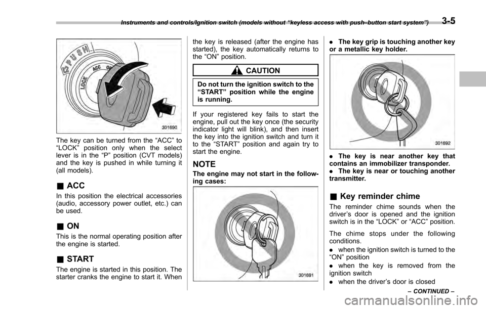
The key can be turned from the“ACC”to
“ LOCK ”position only when the select
lever is in the “P”position (CVT models)
and the key is pushed in while turning it
(all models).
& ACC
In this position the electrical accessories
(audio, accessory power outlet, etc.) can
be used.
&ON
This is the normal operating position after
the engine is started.
&START
The engine is started in this position. The
starter cranks the engine to start it. When the key is released (after the engine has
started), the key automatically returns to
the
“ON ”position.
CAUTION
Do not turn the ignition switch to the
“START ”position while the engine
is running.
If your registered key fails to start the
engine, pull out the key once (the security
indicator light will blink), and then insert
the key into the ignition switch and turn it
to the “START ”position and again try to
start the engine.
NOTE
The engine may not start in the follow-
ing cases:
. The key grip is touching another key
or a metallic key holder.
. The key is near another key that
contains an immobilizer transponder.
. The key is near or touching another
transmitter.
& Key reminder chime
The reminder chime sounds when the
driver ’s door is opened and the ignition
switch is in the “LOCK ”or “ACC ”position.
The chime stops under the following
conditions.
. when the ignition switch is turned to the
“ON ”position
. when the key is removed from the
ignition switch
. when the driver ’s door is closed
Instruments and controls/Ignition switch (models without “keyless access with push –button start system ”)
– CONTINUED –3-5
Page 152 of 594
issue although no malfunction actually
occurs, or not to issue a warning when
any malfunction occurs.–On the instrument panel
– On the floor
– Inside the glove box
– Inside the door trim pocket
– On the rear seat
– On the rear shelf (4-door)
– Inside the trunk (4-door)
– In the cargo area (5-door)
. When operating the push-button
ignition switch or starting the engine,
if the access key battery is discharged,
perform the procedure described in
“Access key –if access key does not
operate properly ”F9-18. In such a
case, replace the battery immediately.
Refer to “Replacing battery of access
key” F11-44.& Switching power
1) Operation indicator
2) Push-button ignition switch
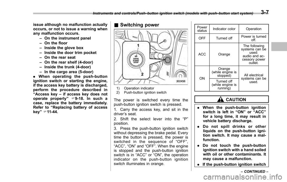
The power is switched every time the
push-button ignition switch is pressed.
1. Carry the access key, and sit in the
driver ’s seat.
2. Shift the select lever into the “P ”
position.
3. Press the push-button ignition switch
without depressing the brake pedal. Every
time the button is pressed, the power is
switched in the sequence of “OFF ”,
“ACC ”, “ON ”and “OFF ”. When the engine
is stopped and the push-button ignition
switch is in “ACC”or “ON ”, the operation
indicator on the push-button ignition
switch illuminates in orange.
Power status Indicator color Operation
OFF Turned off Power is turned
off.
ACC Orange The following
systems can be used:
audio and ac-
cessory power
outlet.
ON Orange
(while engine is stopped) All electrical
systems can be
used.
Turned off
(while engine is
running)
CAUTION
.When the push-button ignition
switch is left in “ON ”or “ACC ”
for a long time, it may result in
vehicle battery discharge.
. Do not spill drinks or other
liquids on the push-button igni-
tion switch. It may cause a mal-
function.
. Do not touch the push-button
ignition switch with a hand soiled
with oil or other contaminants. It
may cause a malfunction.
. If the push-button ignition switch
Instruments and controls/Push –button ignition switch (models with push –button start system)
–CONTINUED –3-7
Page 163 of 594
Instruments and controls/Warning and indicator lights
After that, this indicator light/warning light
changes toBLUEand maintains illumina-
tion in BLUE. This BLUEilluminated light
turns off when the engine is warmed up
sufficiently.
If the engine coolant temperature in-
creases over the specified range, the
indicator light/warning light blinks in
RED . At this time, the engine is close to
overheating.
If the engine coolant temperature in-
creases further, the indicator light/warning
light illuminates in REDcontinuously. At
this time, the engine may be overheating.
When the indicator light/warning light
blinks in REDor illuminates in RED, safely
stop the vehicle as soon as possible, and
refer to the emergency steps to take in the
case of engine overheating. Refer to
“Engine overheating ”F 9-13. After that,
have the system checked by your nearest
SUBARU dealer.
Also, if the indicator light/warning light
often blinks in RED, the electrical system
may be malfunctioning. Contact your
SUBARU dealer for an inspection.
NOTE
If the engine is restarted after a certain
driving condition, this indicator light/ warning light may illuminate in RED.
However, this is not a malfunction if the
indicator light/warning light turns off
after a short time.
&Charge warning light
If this light illuminates when the engine is
running, it may indicate that the charging
system is not working properly.
If the light illuminates while driving or does
not turn off after the engine starts, stop the
engine at the first safe opportunity and
check the alternator belt. If the belt is
loose, broken or if the belt is in good
condition but the light remains illuminated,
contact your nearest SUBARU dealer
immediately.
&Oil pressure warning
light
If this light illuminates when the engine is
running, it may indicate that the engine oil
pressure is low and the lubricating system
is not working properly.
If the light illuminates while driving or does
not turn off after the engine starts, stop the
engine at the first safe opportunity and
check the engine oil level. If the oil level is
low, add oil immediately. If the engine oil is
at the proper level but the light remainsilluminated, contact your nearest
SUBARU dealer immediately.
For details about checking the engine oil
level or adding the engine oil, refer to
“Engine oil
”F 11-8.
CAUTION
Do not operate the engine with the
oil pressure warning light illumi-
nated. This may cause serious en-
gine damage.
&Engine low oil level
warning light
This light illuminates when the engine oil
level decreases to the lower limit.
If the engine low oil level warning light
illuminates while driving, park the vehicle
in a safe and level location, and then
check the engine oil level. When the
engine oil level is not within the normal
range, refill with engine oil. Refer to
“Engine oil ”F 11-8.
If the warning light does not turn off after
refilling the engine oil, or the warning light
illuminates even though the engine oil
level is within the normal range, have the
vehicle checked by a SUBARU dealer.
3-18
Page 164 of 594
NOTE
.After replacing or adding the engine
oil, if the engine oil level is within the
normal range when restarting the en-
gine on a level surface, the warning
light will turn off.
. The warning light may illuminate
temporarily in the following conditions
because a low oil level may be detected
as a result of significant oil movement
in the engine.
–when the vehicle is considerably
inclined on an uphill or steep slope
– when the vehicle has continu-
ously accelerated and decelerated
– when the vehicle is continuously
turned
– when the vehicle is driven on a
road that alternates continuously
between uphill and downhill
&Windshield washer
fluid warning light
This light illuminates when the fluid level in
the windshield washer fluid tank de-
creases to the lower limit (approximately
1.1 US qt, 1.0 liter, 0.9 Imp qt).
&AT OIL TEMP warning
light (CVT models)
If this light illuminates when the engine is
running, it may indicate that the transmis-
sion fluid temperature is too hot.
If the light illuminates while driving, im-
mediately stop the vehicle in a safe place
and let the engine idle until the warning
light turns off.
! Transmission control system warn-
ing
If the “AT OIL TEMP ”warning light flashes
after the engine has started, it may
indicate that the transmission control
system is not working properly. Contact
your nearest SUBARU dealer for service
immediately.
&Low tire pressure
warning light (U.S.-spec.
models)
When the ignition switch is turned to the
“ON ”position, the low tire pressure warn-
ing light will illuminate for approximately 2
seconds to check that the tire pressure
monitoring system (TPMS) is functioning
properly. If there is no problem and all tires
are properly inflated, the light will turn off.
Each tire, including the spare (if provided), should be checked monthly when cold
and inflated to the inflation pressure
recommended by the vehicle manufac-
turer on the vehicle placard or tire inflation
pressure label. (If your vehicle has tires of
a different size than the size indicated on
the vehicle placard or tire inflation pres-
sure label, you should determine the
proper tire inflation pressure for those
tires.)
As an added safety feature, your vehicle
has been equipped with a tire pressure
monitoring system (TPMS) that illuminates
a low tire pressure telltale when one or
more of your tires is significantly under-
inflated. Accordingly, when the low tire
pressure telltale illuminates, you should
stop and check your tires as soon as
possible, and inflate them to the proper
pressure. Driving on a significantly under-
inflated tire causes the tire to overheat and
can lead to tire failure. Under-inflation also
reduces fuel efficiency and tire tread life,
and may affect the vehicle
’s handling and
stopping ability.
Please note that the TPMS is not a
substitute for proper tire maintenance,
and it is the driver ’s responsibility to
maintain correct tire pressure, even if
under-inflation has not reached the level
to trigger illumination of the TPMS low tire
pressure telltale.
Instruments and controls/Warning and indicator lights
–CONTINUED –3-19
Page 167 of 594
Instruments and controls/Warning and indicator lights
switch in the“ON”position and with the
parking brake fully released.
If the brake system warning light should
illuminate while driving (with the parking
brake fully released and with the ignition
switch positioned in “ON”), it could be an
indication of leaking of brake fluid or worn
brake pads. If this occurs, immediately
stop the vehicle at the nearest safe
location and check the brake fluid level.
If the fluid level is below the “MIN”mark in
the reservoir, do not drive the vehicle.
Have the vehicle towed to the nearest
SUBARU dealer for repair.
! Electronic Brake Force Distribution
(EBD) system warning
The brake system warning light also
illuminates if a malfunction occurs in the
EBD system. In that event, it illuminates
together with the ABS warning light.
The EBD system may be malfunctioning if
the brake system warning light and ABS
warning light illuminate simultaneously
during driving.
Even if the EBD system fails, the conven-
tional braking system will still function.
However, the rear wheels will be more
prone to locking when the brakes are
applied harder than usual and the vehi-
cle ’s motion may therefore become some-
what harder to control. If the brake system warning light and ABS
warning light illuminate simultaneously,
take the following steps.
1. Stop the vehicle in the nearest safe,
flat location.
2. Shut down the engine, apply the
parking brake and then restart it.
3. Release the parking brake. Even if
both warning lights turn off, the EBD
system may be malfunctioning. Drive
carefully to the nearest SUBARU dealer
and have the system inspected.
4. If both warning lights illuminate again
and remain illuminated after the engine
has been restarted, shut down the engine
again, apply the parking brake, and check
the brake fluid level.
5. If the brake fluid level is not below the
“
MIN ”mark, the EBD system may be
malfunctioning. Drive carefully to the
nearest SUBARU dealer and have the
system inspected.
6. If the brake fluid level is below the
“ MIN ”mark, DO NOT drive the vehicle.
Instead, have the vehicle towed to the
nearest SUBARU dealer for repair.
&Low fuel warning light
The low fuel warning light illuminates
when the tank is nearly empty, at approxi-
mately 2.6 US gal (10.0 liters, 2.2 Imp gal). It only operates when the ignition switch is
in the
“ON”position.
CAUTION
Promptly put fuel in the tank when-
ever the low fuel warning light
illuminates. Engine misfires as a
result of an empty tank could cause
damage to the engine.
NOTE
This light does not turn off unless the
tank is replenished up to an internal
fuel quantity of approximately 4.5 US
gal (17 liters, 3.7 Imp gal).
&Hill start assist warning
light/Hill start assist
OFF indicator light
! Hill start assist warning light
While the engine is running, if there are
any malfunctions in the Hill start assist
system, the warning light will illuminate.
WARNING
When the Hill start assist warning
light illuminates, have the vehicle
inspected at an authorized SUBARU
3-22
Page 267 of 594
Climate control/Manual climate control operation
!“DUAL ”mode (type D)
You can change the setting of the driver ’s
side and front passenger ’s side tempera-
ture independently by selecting the
“ DUAL ”mode.
You can select the “DUAL ”mode by
performing either of the following proce-
dures.
. Press the “DUAL”button
. Turn the passenger ’s side temperature
control dial
The “DUAL ”mode can be canceled by
pressing the “DUAL”button.
When the “DUAL”mode is selected:
Turn the driver ’ssidedialtosetthe
driver ’s side temperature. Turn the front
passenger ’ssidedialtosetthefront
passenger ’s side temperature.
When the “DUAL”mode is canceled:
Set the desired temperature by turning the
driver ’s side dial.
& Fan speed control
The fan operates only when the ignition
switch is in the “ON ”position. Select the
preferred fan speed by turning the fan
speed control dial.
& Air conditioner control
The air conditioner operates only when
the engine is running.
Press the air conditioner button while the
fan is in operation to turn on the air
conditioner. When the air conditioner is
on, the “A/C ”indicator light illuminates.
To turn off the air conditioner, press the
button again.
NOTE
For efficient defogging or dehumidify-
ing in cold weather, turn on the air
conditioner. However, if the ambient
temperature decreases to approxi-
mately 32 8F(0 8C), the air conditioner
compressor will stop operating.
& Air inlet selection
Select the air inlet by pressing the air inlet
selection button.
ON position (recirculation): Interior air is
recirculated inside the vehicle. Press the
air inlet selection button to the ON position
for fast cooling with the air conditioner or
when driving on a dusty road.
OFF position (outside air): Outside air is
drawn into the passenger compartment.
Press the air inlet selection button to the
OFF position when the interior has cooled to a comfortable temperature and the road
is no longer dusty.
WARNING
Continued operation in the ON posi-
tion may fog up the windows. Switch
to the OFF position as soon as the
outside conditions are no longer
dusty.
NOTE
.
When the indicator light on the air
inlet selection button is flashing at
engine starting, a malfunction might
be occurring in the electrical system.
Contact your SUBARU dealer for in-
spection.
. The indicator light on the air inlet
selection button may flash in the
following cases. However, this does
not indicate a malfunction.
–After the vehicle battery has been
disconnected and reconnected.
– When the vehicle battery voltage
is low.
4-10
Page 363 of 594

Audio/What to do if...
In other situations
SymptomLikely cause SolutionPage
Cell
phone This
system
Even though all conceivable mea-
sures have been taken, the symptom
status does not change. The cell phone is not close enough to
this system.
Bring the cell phone closer to this system.
——
The cell phone is the most likely cause
of the symptom. Turn the cell phone off, remove and reinstall
the battery pack, and then restart the cell
phone.
*
—
Enable the cell phone ’s Bluetooth connection. * —
Stop the cell phone ’s security software and
close all applications. *
—
Before using an application installed on the
cell phone, carefully check its source and how
its operation might affect this system. *
—
*: For details, refer to the owner ’s manual that came with the cell phone.
5-92
Page 386 of 594

Fuel...................................................................... 7-3Fuel requirements ............................................... 7-3
Fuel filler lid and cap ........................................... 7-4
State emission testing (U.S. only) ...................... 7-7
Preparing to drive ............................................... 7-8
Starting and stopping the engine (models without push-button start system) .................. 7-9
Starting engine.................................................... 7-9
Stopping the engine ........................................... 7-11
Starting and stopping engine (models with
push-button start system) .............................. 7-12
Safety precautions............................................. 7-12
Operating range for push-button start system ............................................................. 7-12
Starting engine ................................................... 7-12
Stopping engine ................................................. 7-13
When access key does not operate properly ....... 7-14
Remote engine start system (dealer
option) .............................................................. 7-14
Models with “keyless access with push-button
start system ”................................................... 7-15
Models without “keyless access with push-button
start system ”................................................... 7-16
Entering the vehicle while it is running via remote start ................................................................. 7-19
Entering the vehicle following remote engine start shutdown ......................................................... 7-19
Pre-heating or pre-cooling the interior of the vehicle ............................................................. 7-19
Service mode (models without “keyless access
with push-button start system ”)........................ 7-19 Remote transmitter program (models without
“keyless access with push-button start
system ”).......................................................... 7-19
System maintenance .......................................... 7-20
Manual transmission ......................................... 7-22Shifting speeds.................................................. 7-22
Driving tips ........................................................ 7-23
Continuously variable transmission ................. 7-23Continuously variable transmission features . ..... 7-24
Select lever ....................................................... 7-24
Selection of manual mode (if equipped) .............. 7-26
Selection of “L”(if equipped) ... .......................... 7-28
Shift lock function ............................................. 7-28
Driving tips ........................................................ 7-29
Power steering ................................................... 7-30Power steering warning light .............................. 7-30
Power steering system features ......................... 7-30
Braking............................................................... 7-31Braking tips ....................................................... 7-31
Brake system .................................................... 7-31
Disc brake pad wear warning indicators ............. 7-32
ABS (Anti-lock Brake System).......................... 7-32ABS self-check.................................................. 7-32
ABS warning light .............................................. 7-33
Electronic Brake Force Distribution (EBD)
system ............................................................. 7-33
Steps to take if EBD system malfunctions .......... 7-33
Vehicle Dynamics Control system.................... 7-34Safety precautions............................................. 7-34
System features ................................................. 7-35
Vehicle Dynamics Control system monitor .......... 7-36
Starting and operating
7