2016 SUBARU IMPREZA radiator
[x] Cancel search: radiatorPage 84 of 594
3. If wearing excessive layers of clothing,
the front passenger should remove any
unnecessary items before sitting in the
front passenger’s seat, or should sit in a
rear seat.
4. Turn the ignition switch to the “ON”
position and wait 6 seconds to allow the
system to complete self-checking. Follow-
ing the system check, both indicators turn
off for 2 seconds. Now, the ON indicator
should illuminate while the OFF indicator
remains off.
If the OFF indicator still remains illumi-
nated while the ON indicator remains off,
ask the occupant to move to the rear seat
and immediately contact your SUBARU
dealer for an inspection.
! How to contact the vehicle manu-
facturer concerning modifications
for persons with disabilities that
may affect the advanced airbag
system
Changing or moving any parts of the front
seats, rear seat, seatbelts, front bumper,
front side frame, radiator panel, instrument
panel, combination meter, steering wheel,
steering column, tire, suspension or floor
panel can affect the operation of the
SUBARU advanced airbag system. If
you have any questions, you may contact
the following SUBARU distributors.
Subaru of America, Inc.
Customer Dealer Services Department
P.O. Box 6000
Cherry Hill, NJ 08034-6000
1-800-SUBARU3 (1-800-782-2783)
Subaru Hawaii
2850 Pukoloa Street, Suite 202,
Honolulu, HI 96819-4467
808-839-2273
Shen
’s Corporation dba Prestige Automo-
bile
491, East Marine Corps Drive, Route 1
Dededo, Guam 96921-6225
671-633-2698
Trebol Motors
P.O. Box 11204, San Juan, Puerto Rico
00910
787-793-2828
Subaru Canada, Inc.
Consumer Support Department
560 Suffolk Court, Mississauga, Ontario
L5R 4J7
1-800-894-4212
There are currently no SUBARU distribu-
tors in any other U.S. territories. If you are
in such an area, please contact the
SUBARU distributor or dealer from which
you bought your vehicle.
Seat, seatbelt and SRS airbags/*SRS airbag (Supplemental Restraint System airbag)
–CONTINUED –1-53
Page 268 of 594
Defrosting
&Type A and B
Select the “”or “”mode by turning the
airflow mode selection dial to defrost or
dehumidify the windshield and front door
windows.
& Type C
Select the “”mode by pressing the
defroster button, or select the “”mode
by turning the airflow mode selection dial
to defrost or dehumidify the windshield
and front door windows.
& Type D
Select the “”mode by pressing the
defroster button, or select the “”mode
by pressing the airflow mode selection
button to defrost or dehumidify the wind-
shield and front door windows.
NOTE
. When the “”or “”mode is
selected, the air conditioner compres-
sor operates automatically regardless
of the position of the air conditioner
button to defrost the windshield more
quickly. However the indicator on the
air conditioner button will not illumi-
nate. At the same time, the air inlet selection is automatically set to the
outside air mode.
For type A climate control system, in
this state:
–You cannot stop the air condi-
tioner compressor by pressing the
air conditioner button.
– You cannot select the recircula-
tion mode by pressing the air inlet
selection button.
. For type C and D climate control
system, after defrosting the windshield
by pressing the defroster button “
”,
pressing the button again returns the
system to the setting that had been
selected before the defroster was acti-
vated.
Operating tips for heater and
air conditioner
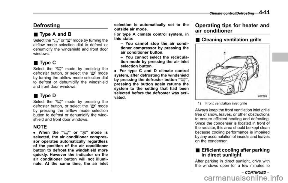
& Cleaning ventilation grille
1) Front ventilation inlet grille
Always keep the front ventilation inlet grille
free of snow, leaves, or other obstructions
to ensure efficient heating and defrosting.
Since the condenser is located in front of
the radiator, this area should be kept clean
because cooling performance is impaired
by any accumulation of insects and leaves
on the condenser.
&Efficient cooling after parking
in direct sunlight
After parking in direct sunlight, drive with
the windows open for a few minutes to
Climate control/Defrosting
–CONTINUED –4-11
Page 482 of 594
Engine overheating
WARNING
Never attempt to remove the radia-
tor cap until the engine has been
shut off and has fully cooled down.
When the engine is hot, the coolant
is under pressure. Removing the
cap while the engine is still hot
could release a spray of boiling hot
coolant, which could burn you very
seriously.
If the engine overheats, safely pull off the
road and stop the vehicle in a safe
location.
& If steam is coming from the
engine compartment
. Turn the ignition switch to the “LOCK”/
“OFF ”position and get everyone away
from the vehicle until it cools down.
. Contact an authorized SUBARU deal-
er.
& If no steam is coming from
the engine compartment
1. Keep the engine running at idling
speed. 2. Open the engine hood to ventilate the
engine compartment. Refer to
“Engine
hood ”F 11-5.
Confirm that the cooling fan is turning. If
the fan is not turning, immediately turn off
the engine and contact an authorized
SUBARU dealer for repair.
3. After the coolant temperature high
warning light that has blinked or illumi-
nated in REDturns off, turn off the engine.
For details about the warning light, refer to
“Coolant temperature low indicator light/
Coolant temperature high warning light ”
F 3-17.
4. After the engine has fully cooled down,
check the coolant level in the reserve
tank. If the coolant level is below the
“LOW ”mark, add coolant up to the “FULL ”
mark.
NOTE
For details about how to check the
coolant level or how to add coolant,
refer to “Engine coolant ”F 11-11.
5. If there is no coolant in the reserve
tank, add coolant to the reserve tank.
Then remove the radiator cap and fill the
radiator with coolant.
If you remove the radiator cap from a hot
radiator, first wrap a thick cloth around the
radiator cap, then turn the cap counter- clockwise slowly without pressing down
until it stops. Release the pressure from
the radiator. After the pressure has been
fully released, remove the cap by pressing
down and turning it.
In case of emergency/Engine overheating9-13
Page 502 of 594
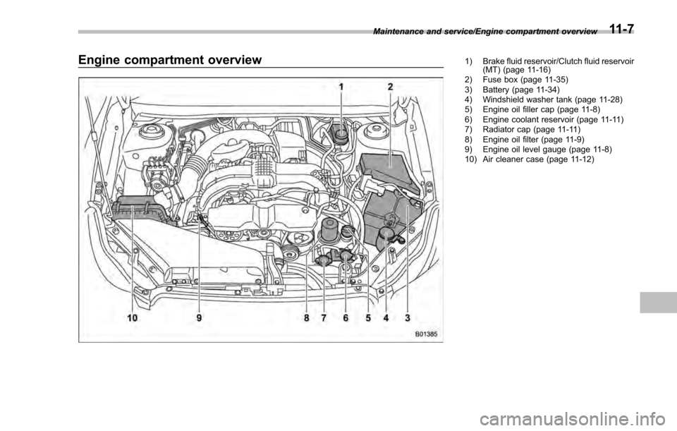
Engine compartment overview1) Brake fluid reservoir/Clutch fluid reservoir(MT) (page 11-16)
2) Fuse box (page 11-35)
3) Battery (page 11-34)
4) Windshield washer tank (page 11-28)
5) Engine oil filler cap (page 11-8)
6) Engine coolant reservoir (page 11-11)
7) Radiator cap (page 11-11)
8) Engine oil filter (page 11-9)
9) Engine oil level gauge (page 11-8)
10) Air cleaner case (page 11-12)
Maintenance and service/Engine compartment overview
11-7
Page 506 of 594
diluted with another brand or
type, the maintenance interval is
shortened to that of the mixing
coolant.
. Do not splash the engine coolant
over painted parts. The alcohol
contained in the engine coolant
may damage the paint surface.
& Cooling fan, hose and con-
nections
Your vehicle employs an electric cooling
fan which is thermostatically controlled to
operate when the engine coolant reaches
a specific temperature.
If the radiator cooling fan does not operate
even when the coolant temperature high
warning light blinks or illuminates in RED,
the cooling fan circuit may be defective.
Refer to “Coolant temperature low indica-
tor light/Coolant temperature high warning
light ”F 3-17.
Check the fuse and replace it if necessary.
Refer to “Fuses”F 11-35 and “Fuse panel
located in the engine compartment ”F 12-
12.
If the fuse is not blown, have the cooling
system checked by your SUBARU dealer.
If frequent addition of coolant is neces- sary, there may be a leak in the engine
cooling system. It is recommended that
the cooling system and connections be
checked for leaks, damage, or looseness.
&
Engine coolant
! Checking the coolant level
WARNING
Never attempt to remove the radia-
tor cap until the engine has been
shut off and has cooled down
completely. Since the coolant is
under pressure, you may suffer
serious burns from a spray of boil-
ing hot coolant when the cap is
removed.
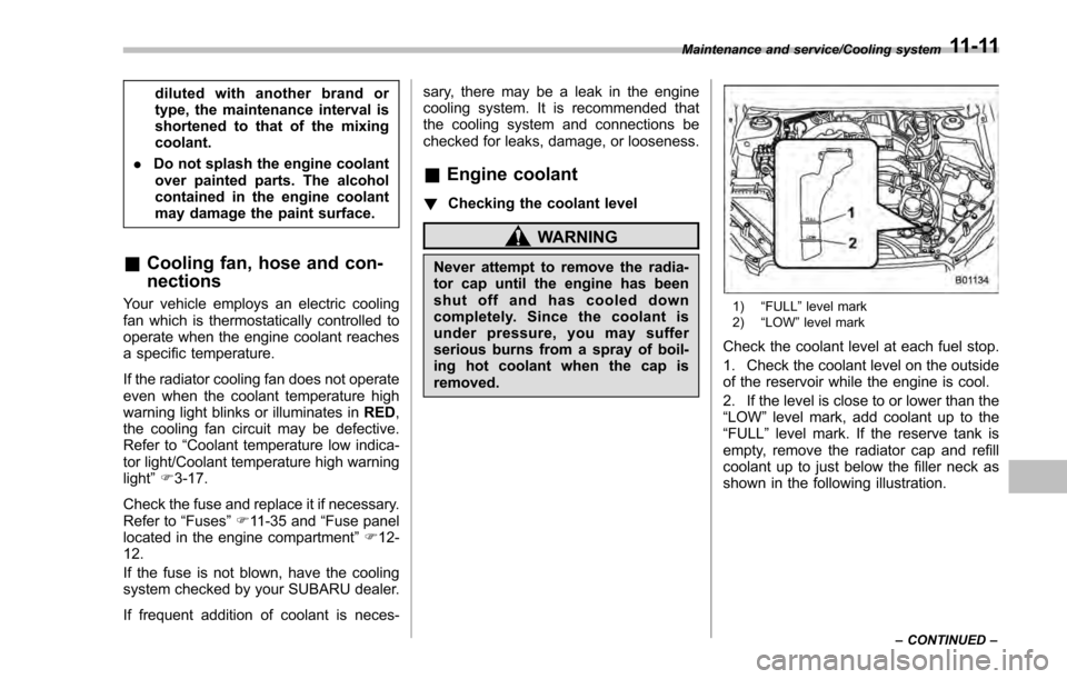
1) “FULL ”level mark
2) “LOW ”level mark
Check the coolant level at each fuel stop.
1. Check the coolant level on the outside
of the reservoir while the engine is cool.
2. If the level is close to or lower than the
“LOW ”level mark, add coolant up to the
“FULL ”level mark. If the reserve tank is
empty, remove the radiator cap and refill
coolant up to just below the filler neck as
shown in the following illustration.
Maintenance and service/Cooling system
–CONTINUED –11-11
Page 507 of 594
Maintenance and service/Air cleaner element
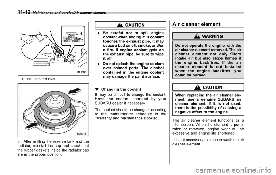
1) Fill up to this level
3. After refilling the reserve tank and the
radiator, reinstall the cap and check that
the rubber gaskets inside the radiator cap
are in the proper position.
CAUTION
.Be careful not to spill engine
coolant when adding it. If coolant
touches the exhaust pipe, it may
cause a bad smell, smoke, and/or
a fire. If engine coolant gets on
the exhaust pipe, be sure to wipe
it off.
. Do not splash the engine coolant
over painted parts. The alcohol
contained in the engine coolant
may damage the paint surface.
! Changing the coolant
It may be difficult to change the coolant.
Have the coolant changed by your
SUBARU dealer if necessary.
The coolant should be changed according
to the maintenance schedule in the
“Warranty and Maintenance Booklet ”.
Air cleaner element
WARNING
Do not operate the engine with the
air cleaner element removed. The air
cleaner element not only filters
intake air but also stops flames if
the engine backfires. If the air
cleaner element is not installed
when the engine backfires, you
could be burned.
CAUTION
When replacing the air cleaner ele-
ment, use a genuine SUBARU air
cleaner element. If it is not used,
there is the possibility of causing a
negative effect to the engine.
The air cleaner element functions as a
filter screen. When the element is perfo-
rated or removed, engine wear will be
excessive and engine life shortened.
It is not necessary to clean or wash the air
cleaner element.
11-12
Page 552 of 594

Fuse
panel Fuse
rating Circuit
15 10A .Luggage light
. Clock
16 7.5A .Illumination
17 15A .Seat heaters
18 10A .Backup light
19 7.5A .Power window relay
. Radiator main fan relay
20 10A .Accessory power outlet
(instrument panel)
21 10A .Starter relay
22 7.5A .Air conditioner
. Rear window defogger
relay coil
23 Empty
24 10A .Audio unit
. Clock
25 15A .SRS airbag system
26 Empty
27 15A .Blower fan
28 15A .Blower fan
29 15A .Fog light
30 Empty
31 7.5A .Auto air conditioner unit
. Integrated unit Fuse
panel Fuse
rating Circuit
32 7.5A .Clutch switch
. Steering lock control
unit
33 7.5A .Vehicle Dynamics Con-
trol unit Specifications/Fuses and circuits
–CONTINUED –
12-11