2016 SUBARU IMPREZA brake
[x] Cancel search: brakePage 8 of 594

&Abbreviation list
You may find several abbreviations in this
manual. The meanings of the abbrevia-
tions are shown in the following list.
Abbreviation Meaning
A/C Air conditioner
ALR/ELR Automatic locking retractor/
Emergency locking retractor
ABS Anti-lock brake system
AKI Anti knock index
ALR Automatic locking retractor
AWD All-wheel drive
BSD/RCTA Blind Spot Detection/Rear
Cross Traffic Alert
CVT Continuously variable trans-
mission
DRL Daytime running light
EBD Electronic brake force distri-
bution
ELR Emergency locking retractor
GAW Gross axle weight
GAWR Gross axle weight rating
GPS Global positioning system
GVW Gross vehicle weight
GVWR Gross vehicle weight rating
HID High intensity discharge Abbreviation
Meaning
INT Intermittent
LATCH Lower anchors and tethers for
children
LED Light emitting diode
MIL Malfunction indicator light
MMT Methylcyclopentadienyl man-
ganese tricarbonyl
MT Manual transmission
OBD On-board diagnostics
RON Research octane number
SRF Steering responsive fog lights
system
SRS Supplemental restraint sys-
tem
TIN Tire identification number
TPMS Tire pressure monitoring sys-
tem
Vehicle symbols
There are some of the symbols you may
see on your vehicle.
For warning and indicator lights, refer to
“
Warning and indicator lights ”F 22.
Mark Name
WARNING
CAUTION
Read these instructions care-
fully
Wear eye protection
Battery fluid contains sulfuric
acid
Keep children away
Keep flames away
Prevent explosions
3
Page 13 of 594

General information
&California proposition 65
warning
WARNING
Engine exhaust, some of its consti-
tuents, and certain vehicle compo-
nents contain or emit chemicals
known to the State of California to
cause cancer and birth defects or
other reproductive harm. In addi-
tion, certain fluids in vehicles and
certain components of product wear
contain or emit chemicals known to
the State of California to cause
cancer and birth defects or other
reproductive harm.
&California Perchlorate Advi-
sory
Certain vehicle components such as air-
bag modules, seatbelt pretensioners and
keyless entry transmitter batteries may
contain perchlorate material. Special
handling may apply for service or vehicle
end of life disposal. See www.dtsc.ca.gov/
hazardouswaste/perchlorate.
&Noise from under the vehicle
NOTE
You may hear a noise from under the
vehicle approximately 5 to 10 hours
after the ignition switch is turned to the
“LOCK ”/“OFF ”position. However, this
does not indicate a malfunction. This
noise is caused by the operation of the
fuel evaporation leakage checking sys-
tem and the operation is normal. The
noise will stop after approximately 15
minutes.
& Event data recorder
This vehicle is equipped with an event
data recorder (EDR). The main purpose of
an EDR is to record, in certain crash or
near crash-like situations, such as an air
bag deployment or hitting a road obstacle,
data that will assist in understanding how
a vehicle’ s systems performed. The EDR
is designed to record data related to
vehicle dynamics and safety systems for
a short period of time, typically 30 seconds
or less. The EDR in this vehicle is
designed to record such data as:
. How various systems in your vehicle
were operating;
. Whether or not the driver and passen-
ger safety belts were buckled/fastened;
. How far (if at all) the driver was depressing the accelerator and/or brake
pedal; and,
.
How fast the vehicle was traveling.
These data can help provide a better
understanding of the circumstances in
which crashes and injuries occur. NOTE:
EDR data are recorded by your vehicle
only if a non-trivial crash situation occurs;
no data are recorded by the EDR under
normal driving conditions and no personal
data (e.g., name, gender, age, and crash
location) are recorded. However, other
parties, such as law enforcement, could
combine the EDR data with the type of
personally identifying data routinely ac-
quired during a crash investigation.
To read data recorded by an EDR, special
equipment is required, and access to the
vehicle or the EDR is needed. In addition
to the vehicle manufacturer, other parties,
such as law enforcement, that have the
special equipment, can read the informa-
tion if they have access to the vehicle or
the EDR.
8
Page 18 of 594

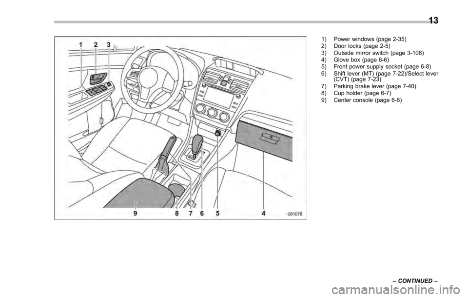
1) Power windows (page 2-35)
2) Door locks (page 2-5)
3) Outside mirror switch (page 3-108)
4) Glove box (page 6-6)
5) Front power supply socket (page 6-8)
6) Shift lever (MT) (page 7-22)/Select lever(CVT) (page 7-23)
7) Parking brake lever (page 7-40)
8) Cup holder (page 6-7)
9) Center console (page 6-6)
–CONTINUED –
13
Page 27 of 594

&Warning and indicator lights
Mark Name Page
Seatbelt warning light 3-14
Front passenger’s
seatbelt warning light 3-14
SRS airbag system
warning light3-15
/Front passenger
’s
frontal airbag ON indi-
cator 3-16
/Front passenger
’s
frontal airbag OFF in-
dicator 3-16
CHECK ENGINE
warning light/Malfunc-
tion indicator light3-16
Coolant temperature
low indicator light/
Coolant temperature
high warning light3-17
Charge warning light 3-18
Oil pressure warning
light
3-18
Engine oil level warn-
ing light3-18Mark Name Page
AT OIL TEMP warning
light (CVT models)
3-19
ABS warning light 3-21
Brake system warning
light
3-21
Door open warning
light3-23
AWD warning light
(CVT models)
3-23
Power steering warn-
ing light3-23
Hill start assist warn-
ing light/Hill start assist
OFF indicator light3-22
Vehicle Dynamics
Control warning light/
Vehicle Dynamics
Control operation indi-
cator light3-24
Vehicle Dynamics
Control OFF indicator
light
3-25
Turn signal indicator
lights
3-31Mark Name Page
High beam indicator
light
3-31
Automatic headlight
beam leveler warning
light (if equipped)3-31
Front fog light indicator
light (if equipped)
3-31
Access key warning
indicator (if equipped)3-25
Security indicator light 3-30
Headlight indicator
light (if equipped)
3-32
Cruise control indica-
tor light (if equipped)3-31
Cruise control set in-
dicator light (if
equipped)3-31
Low fuel warning light 3-22
Low tire pressure
warning light
(U.S.-spec. models)3-19
Windshield washer
fluid warning light
3-19
22
Page 146 of 594

Ignition switch (models without“keyless
access with push-button start system ”)......... 3-4
LOCK .................................................................. 3-4
ACC.................................................................... 3-5
ON...................................................................... 3-5
START ................................................................ 3-5
Key reminder chime ............................................ 3-5
Ignition switch light (if equipped) ......................... 3-6
Push-button ignition switch (models with
push-button start system) ............................... 3-6
Safety precautions.............................................. 3-6
Operating range for push-button start system ...... 3-6
Switching power ................................................. 3-7
When access key does not operate properly ........ 3-8
Hazard warning flasher....................................... 3-8
Meters and gauges. ............................................. 3-9
Combination meter illumination ........................... 3-9
Canceling the function for meter/gauge needle movement upon turning on the ignition
switch ............................................................... 3-9
Speedometer ...................................................... 3-10
Odometer ........................................................... 3-10
Double trip meter ............................................... 3-11
Tachometer ........................................................ 3-11
Fuel gauge ......................................................... 3-12
ECO gauge (if equipped) .................................... 3-12
Warning and indicator lights ............................. 3-13Initial illumination for system check .................... 3-13
Seatbelt warning light and chime ........................ 3-14
SRS airbag system warning light ........................ 3-15Front passenger
’s frontal airbag ON and OFF
indicators ........................................................ 3-16
CHECK ENGINE warning light/Malfunction indicator light .................................................. 3-16
Coolant temperature low indicator light/Coolant temperature high warning light ......................... 3-17
Charge warning light .......................................... 3-18
Oil pressure warning light .................................. 3-18
Engine low oil level warning light ....................... 3-18
Windshield washer fluid warning light ................ 3-19
AT OIL TEMP warning light (CVT models) ........... 3-19
Low tire pressure warning light (U.S.-spec. models) ........................................................... 3-19
ABS warning light .............................................. 3-21
Brake system warning light (red) ........................ 3-21
Low fuel warning light ....................................... 3-22
Hill start assist warning light/Hill start assist OFF indicator light .................................................. 3-22
Door open warning light .................................... 3-23
All-Wheel Drive warning light (CVT models) ... ..... 3-23
Power steering warning light .............................. 3-23
Vehicle Dynamics Control warning light/Vehicle Dynamics Control operation indicator light .. ..... 3-24
Vehicle Dynamics Control OFF indicator light ..... 3-25
Warning chimes and warning indicator of the keyless access with push-button start system (if
equipped) ........................................................ 3-25
Security indicator light ....................................... 3-30
Select lever/gear position indicator (CVT models) ........................................................... 3-30
Turn signal indicator lights ................................. 3-31
High beam indicator light ................................... 3-31
Instruments and controls
3
Page 152 of 594

issue although no malfunction actually
occurs, or not to issue a warning when
any malfunction occurs.–On the instrument panel
– On the floor
– Inside the glove box
– Inside the door trim pocket
– On the rear seat
– On the rear shelf (4-door)
– Inside the trunk (4-door)
– In the cargo area (5-door)
. When operating the push-button
ignition switch or starting the engine,
if the access key battery is discharged,
perform the procedure described in
“Access key –if access key does not
operate properly ”F9-18. In such a
case, replace the battery immediately.
Refer to “Replacing battery of access
key” F11-44.& Switching power
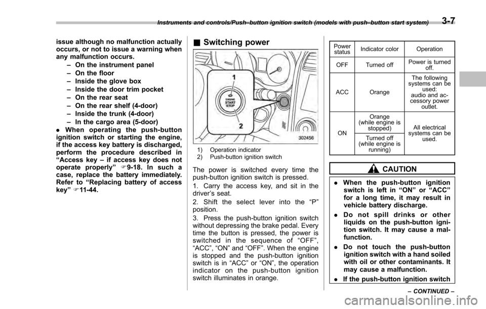
1) Operation indicator
2) Push-button ignition switch
The power is switched every time the
push-button ignition switch is pressed.
1. Carry the access key, and sit in the
driver ’s seat.
2. Shift the select lever into the “P ”
position.
3. Press the push-button ignition switch
without depressing the brake pedal. Every
time the button is pressed, the power is
switched in the sequence of “OFF ”,
“ACC ”, “ON ”and “OFF ”. When the engine
is stopped and the push-button ignition
switch is in “ACC”or “ON ”, the operation
indicator on the push-button ignition
switch illuminates in orange.
Power status Indicator color Operation
OFF Turned off Power is turned
off.
ACC Orange The following
systems can be used:
audio and ac-
cessory power
outlet.
ON Orange
(while engine is stopped) All electrical
systems can be
used.
Turned off
(while engine is
running)
CAUTION
.When the push-button ignition
switch is left in “ON ”or “ACC ”
for a long time, it may result in
vehicle battery discharge.
. Do not spill drinks or other
liquids on the push-button igni-
tion switch. It may cause a mal-
function.
. Do not touch the push-button
ignition switch with a hand soiled
with oil or other contaminants. It
may cause a malfunction.
. If the push-button ignition switch
Instruments and controls/Push –button ignition switch (models with push –button start system)
–CONTINUED –3-7
Page 158 of 594

efficiency.
NOTE
.The ECO gauge shows only an
approximate indication of fuel effi-
ciency.
. After resetting the trip meter, the
average rate of fuel consumption is not
shown until driving 0.6 mile (1 km).
Before that time, the ECO gauge does
not operate.
Warning and indicator lights
& Initial illumination for system
check
Several of the warning and indicator lights
illuminate when the ignition switch is
initially turned to the “ON ”position. This
permits checking the operation of the
bulbs.
Apply the parking brake and turn the
ignition switch to the “ON”position. For
the system check, the following lights
illuminate and then turn off after several
seconds or after the engine has started.
: Seatbelt warning light (The seatbelt warning light turns off
only when the driver fastens the
seatbelt.)
: Front passenger ’s seatbelt warning
light
(The seatbelt warning light turns off
only when the front seat passenger
fastens the seatbelt.)
: SRS airbag system warning light
ON /
: Front passenger ’s frontal airbag
ON indicator light
/: Front passenger ’s frontal airbag
OFF indicator light
: CHECK ENGINE warning light/Mal- function indicator light
: Coolant temperature low indicator light/Coolant temperature high warn-
ing light
: Charge warning light
: Oil pressure warning light
: Engine low oil level warning light
: Windshield washer fluid warning light
: AT OIL TEMP warning light(CVT models)
: Low tire pressure warning light(U.S.- spec. models)
/: ABS warning light
/: Brake system warning light
: Low fuel warning light
: Hill start assist warning light/Hill startassist OFF indicator light
: Door open warning light
: AWD warning light (CVT models)
: Power steering warning light
: Vehicle Dynamics Control warning light/Vehicle Dynamics Control opera-
tion indicator light
Instruments and controls/Warning and indicator lights
–CONTINUED –3-13
Page 165 of 594

Instruments and controls/Warning and indicator lights
Your vehicle has also been equipped with
a TPMS malfunction indicator to indicate
when the system is not operating properly.
The TPMS malfunction indicator is com-
bined with the low tire pressure telltale.
When the system detects a malfunction,
the telltale will flash for approximately one
minute and then remain continuously
illuminated. This sequence will continue
upon subsequent vehicle start-ups as long
as the malfunction exists. When the
malfunction indicator is illuminated, the
system may not be able to detect or signal
low tire pressure as intended. TPMS
malfunctions may occur for a variety of
reasons, including the installation of re-
placement or alternate tires or wheels on
the vehicle that prevent the TPMS from
functioning properly. Always check the
TPMS malfunction telltale after replacing
one or more tires or wheels on your
vehicle to ensure that the replacement or
alternate tires and wheels allow the TPMS
to continue to function properly.
Should the warning light illuminate stea-
dily after blinking for approximately one
minute, have the system inspected by
your nearest SUBARU dealer as soon as
possible.
WARNING
If this light does not illuminatebriefly after the ignition switch is
turned ON or the light illuminates
steadily after blinking for approxi-
mately one minute, you should have
your Tire Pressure Monitoring Sys-
tem checked at a SUBARU dealer as
soon as possible.
If this light illuminates while driving,
never brake suddenly and keep
driving straight ahead while gradu-
ally reducing speed. Then slowly
pull off the road to a safe place.
Otherwise an accident involving
serious vehicle damage and serious
personal injury could occur.
If this light still illuminates while
driving after adjusting the tire pres-
sure, a tire may have significant
damage and a fast leak that causes
the tire to lose air rapidly. If you have
a flat tire, replace it with a spare tire
as soon as possible.
When a spare tire is mounted or a
wheel rim is replaced without the
original pressure sensor/transmitter
being transferred, the Low tire pres-
sure warning light will illuminate
steadily after blinking for approxi-
mately one minute. This indicates
the TPMS is unable to monitor all
four road wheels. Contact your
SUBARU dealer as soon as possiblefor tire and sensor replacement and/
or system resetting.
If the light illuminates steadily after
blinking for approximately one min-
ute, promptly contact a SUBARU
dealer to have the system inspected.
CAUTION
The tire pressure monitoring system
is NOT a substitute for manually
checking tire pressure. The tire
pressure should be checked peri-
odically (at least monthly) using a
tire gauge. After any change to tire
pressure(s), the tire pressure mon-
itoring system will not re-check tire
inflation pressures until the vehicle
is first driven more than 20 mph (32
km/h). After adjusting the tire pres-
sures, increase the vehicle speed to
at least 20 mph (32 km/h) to start the
TPMS re-checking of the tire infla-
tion pressures. If the tire pressures
are now above the severe low
pressure threshold, the low tire
pressure warning light should turn
off a few minutes later. Therefore, be
sure to install the specified size for
the front and rear tires.
3-20