Page 3543 of 3641
WCS-28
< WIRING DIAGRAM >
WARNING CHIME SYSTEM
AANIA3165GB
Revision: August 20152016 Versa Note
cardiagn.com
Page 3544 of 3641
WCS
WARNING CHIME SYSTEMWCS-29
< WIRING DIAGRAM >
C
DE
F
G H
I
J
K L
M B A
O P
ABNIA8037GB
Revision: August 2015 2016 Versa Note
cardiagn.com
Page 3545 of 3641
WCS-30
< WIRING DIAGRAM >
WARNING CHIME SYSTEM
ABNIA8038GB
Revision: August 20152016 Versa Note
cardiagn.com
Page 3546 of 3641
WCS
WARNING CHIME SYSTEMWCS-31
< WIRING DIAGRAM >
C
DE
F
G H
I
J
K L
M B A
O P
ABNIA8039GB
Revision: August 2015 2016 Versa Note
cardiagn.com
Page 3549 of 3641

WCS-34
< DTC/CIRCUIT DIAGNOSIS >
POWER SUPPLY AND GROUND CIRCUIT
DTC/CIRCUIT DIAGNOSIS
POWER SUPPLY AND GROUND CIRCUIT
COMBINATION METER (TYPE A)
COMBINATION METER (TYPE A) : Diagnosis ProcedureINFOID:0000000012542990
Regarding Wiring Diagram information, refer to MWI-26, "Wiring Diagram".
1.CHECK FUSE
Check that the following fuses are not blown.
Is the fuse blown?
YES >> Replace the blown fuse after repairing the affected circuit.
NO >> GO TO 2.
2.POWER SUPPLY CIRCUIT CHECK
1. Disconnect combination meter connector.
2. Check voltage between combination meter harness connector M82, terminals 27, 28, 15 and ground.
Is the inspection result normal?
YES >> GO TO 3.
NO >> Repair or replace harness or connector.
3.GROUND CIRCUIT CHECK
1. Turn ignition switch OFF.
2. Disconnect combination meter connector.
3. Check continuity between combination meter har ness connector M82, terminals 21, 22, 23 and ground.
Is the inspection result normal?
YES >> Inspection End.
NO >> Repair or replace harness or connector.
COMBINATION METER (TYPE B)
Power source Fuse No.
Battery 8
Ignition switch ON or START 3
Ignition switch ACC or ON 18
TerminalsIgnition switch position
(+) (–)OFF ACC ONSTART
Connector Terminal
M82 27
GroundBattery voltage Battery voltage Battery voltage Battery voltage
28 0V0VBattery voltage Battery voltage
15 0V Battery voltage Battery voltage 0V
Te r m i n a l s
Continuity
(+)
(–)
Connector Terminal
M82 21
Ground Yes
22
23
Revision: August 2015 2016 Versa Note
cardiagn.com
Page 3550 of 3641

WCS
POWER SUPPLY AND GROUND CIRCUITWCS-35
< DTC/CIRCUIT DIAGNOSIS >
C
DE
F
G H
I
J
K L
M B A
O P
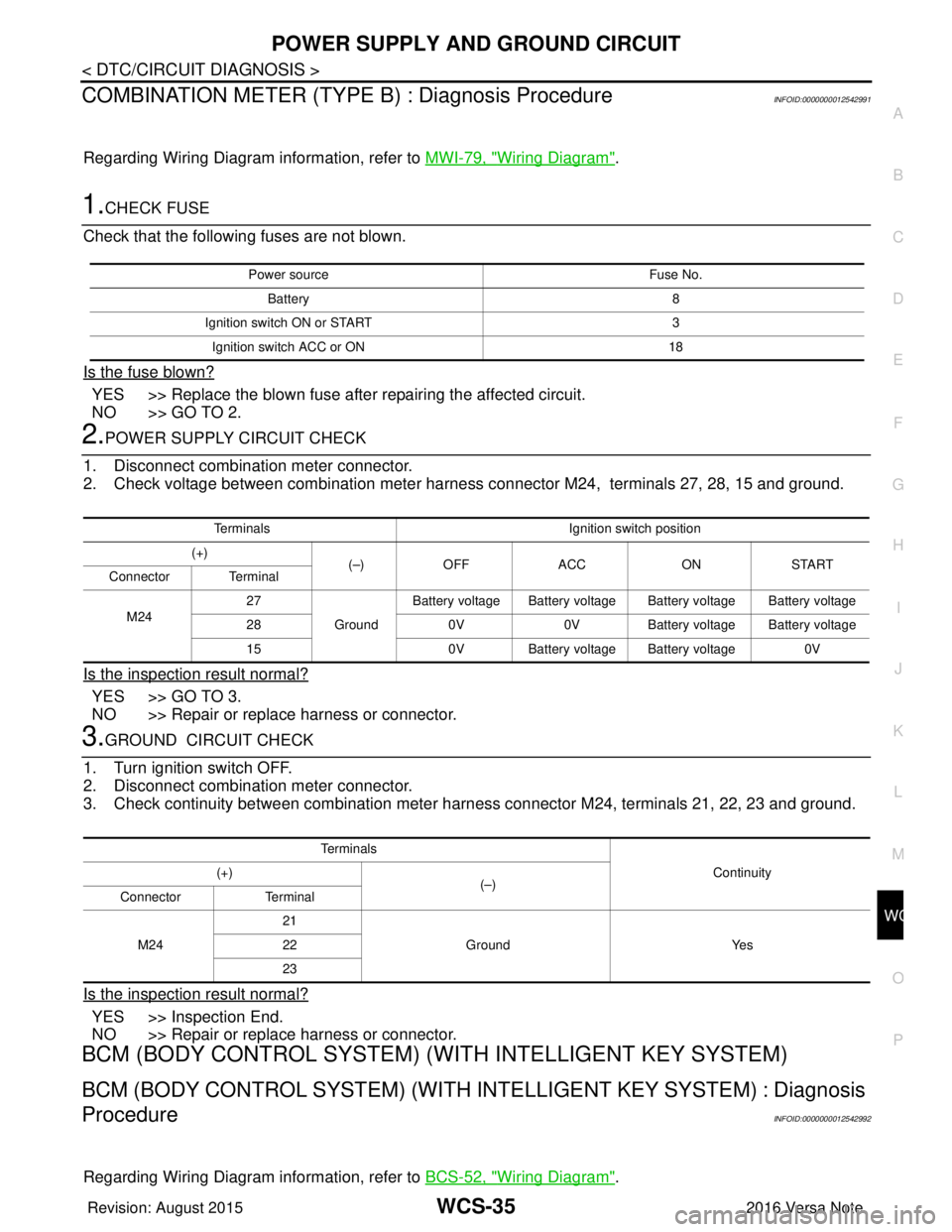
COMBINATION METER (TYPE B) : Diagnosis ProcedureINFOID:0000000012542991
Regarding Wiring Diagram information, refer to MWI-79, "Wiring Diagram".
1.CHECK FUSE
Check that the following fuses are not blown.
Is the fuse blown?
YES >> Replace the blown fuse after repairing the affected circuit.
NO >> GO TO 2.
2.POWER SUPPLY CIRCUIT CHECK
1. Disconnect combination meter connector.
2. Check voltage between combination meter harness connector M24, terminals 27, 28, 15 and ground.
Is the inspection result normal?
YES >> GO TO 3.
NO >> Repair or replace harness or connector.
3.GROUND CIRCUIT CHECK
1. Turn ignition switch OFF.
2. Disconnect combination meter connector.
3. Check continuity between combination meter harness connector M24, terminals 21, 22, 23 and ground.
Is the inspection result normal?
YES >> Inspection End.
NO >> Repair or replace harness or connector.
BCM (BODY CONTROL SYSTEM) (W ITH INTELLIGENT KEY SYSTEM)
BCM (BODY CONTROL SYSTEM) (WITH IN TELLIGENT KEY SYSTEM) : Diagnosis
Procedure
INFOID:0000000012542992
Regarding Wiring Diagram information, refer to BCS-52, "Wiring Diagram".
Power source Fuse No.
Battery 8
Ignition switch ON or START 3
Ignition switch ACC or ON 18
TerminalsIgnition switch position
(+) (–)OFF ACC ONSTART
Connector Terminal
M24 27
GroundBattery voltage Battery voltage Battery voltage Battery voltage
28 0V0VBattery voltage Battery voltage
15 0V Battery voltage Battery voltage 0V
Te r m i n a l s
Continuity
(+)
(–)
Connector Terminal
M24 21
Ground Yes
22
23
Revision: August 2015 2016 Versa Note
cardiagn.com
Page 3551 of 3641

WCS-36
< DTC/CIRCUIT DIAGNOSIS >
POWER SUPPLY AND GROUND CIRCUIT
1.CHECK FUSES AND FUSIBLE LINK
Check that the following fuses and fusible link are not blown.
Is the fuse blown?
YES >> Replace the blown fuse or fusible link after repairing the affected circuit.
NO >> GO TO 2.
2.CHECK POWER SUPPLY CIRCUIT
1. Disconnect BCM connector M99.
2. Check voltage between BCM connector M99 and ground.
Is the inspection result normal?
YES >> GO TO 3.
NO >> Repair harness or connector.
3.CHECK GROUND CIRCUIT
Check continuity between BCM connector M99 and ground.
Is the inspection result normal?
YES >> Inspection End.
NO >> Repair harness or connector.
BCM (BODY CONTROL SYSTEM) (WIT HOUT INTELLIGENT KEY SYSTEM)
BCM (BODY CONTROL SYSTEM) (WITHOUT INTELLIGENT KEY SYSTEM) : Diag-
nosis Procedure
INFOID:0000000012542993
Regarding Wiring Diagram information, refer to BCS-117, "Wiring Diagram".
1.CHECK FUSES AND FUSIBLE LINK
Check that the following fuses and fusible link are not blown.
Terminal No. Signal nameFuses and fusible link No.
57 Battery power supply 12 (10A)
70 G (40A)
BCM
Ground Voltage
Connector Terminal
M99 57
— Battery voltage
70
BCM GroundContinuity
Connector Terminal
M99 67—Yes
Terminal No. Signal nameFuses and fusible link No.
37 Battery power supply 8 (10A)
42 12 (10A)
50 G (40A)
11 Ignition switch ACC or ON 18 (10A)
38 Ignition switch ON or START 2 (10A)
Revision: August 2015 2016 Versa Note
cardiagn.com
Page 3554 of 3641

WCS
SEAT BELT BUCKLE SWITCH SIGNAL CIRCUIT
WCS-39
< DTC/CIRCUIT DIAGNOSIS >
C
D E
F
G H
I
J
K L
M B A
O P
SEAT BELT BUCKLE SW ITCH SIGNAL CIRCUIT
TYPE A
TYPE A : DescriptionINFOID:0000000012432692
Transmits a seat belt buckle switch LH signal to the combination meter.
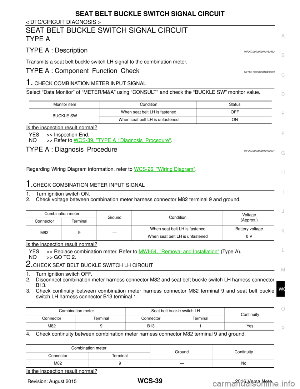
TYPE A : Component Function CheckINFOID:0000000012432693
1. CHECK COMBINATION METER INPUT SIGNAL
Select “Data Monitor” of “METER/M&A” using “C ONSULT” and check the “BUCKLE SW” monitor value.
Is the inspection result normal?
YES >> Inspection End.
NO >> Refer to WCS-39, "
TYPE A : DiagnosisProcedure".
TYPE A : Diagnosis ProcedureINFOID:0000000012432694
Regarding Wiring Diagram information, refer to WCS-26, "Wiring Diagram".
1.CHECK COMBINATION METER INPUT SIGNAL
1. Turn ignition switch ON.
2. Check voltage between combination meter harness connector M82 terminal 9 and ground.
Is the inspection result normal?
YES >> Replace combination meter. Refer to MWI-54, "Removal and Installation" (Type A).
NO >> GO TO 2.
2.CHECK SEAT BELT BUCKLE SWITCH LH CIRCUIT
1. Turn ignition switch OFF.
2. Disconnect combination meter harness connector M82 and seat belt buckle switch LH harness connector
B13.
3. Check continuity between combination meter har ness connector M82 terminal 9 and seat belt buckle
switch LH harness connector B13 terminal 1.
4. Check continuity between combination meter harness connector M82 terminal 9 and ground.
Is the inspection result normal?
Monitor item Condition Status
BUCKLE SW When seat belt LH is fastened
OFF
When seat belt LH is unfastened ON
Combination meter
GroundCondition Vo l ta g e
(Approx.)
Connector Terminal
M82 9— When seat belt LH is fastened
Battery voltage
When seat belt LH is unfastened 0 V
Combination meterSeat belt buckle switch LH
Continuity
Connector TerminalConnector Terminal
M82 9B13 1Yes
Combination meter GroundContinuity
Connector Terminal
M82 9— No
Revision: August 2015 2016 Versa Note
cardiagn.com