2016 NISSAN NOTE ECU
[x] Cancel search: ECUPage 3012 of 3641
![NISSAN NOTE 2016 Service Repair Manual VEHICLE SECURITY INDICATORSEC-155
< DTC/CIRCUIT DIAGNOSIS > [WITHOUT INTELLIGENT KEY SYSTEM]
C
D
E
F
G H
I
J
L
M A
B
SEC
N
O P
VEHICLE SECURITY INDICATOR
DescriptionINFOID:0000000012430486
• Vehicle NISSAN NOTE 2016 Service Repair Manual VEHICLE SECURITY INDICATORSEC-155
< DTC/CIRCUIT DIAGNOSIS > [WITHOUT INTELLIGENT KEY SYSTEM]
C
D
E
F
G H
I
J
L
M A
B
SEC
N
O P
VEHICLE SECURITY INDICATOR
DescriptionINFOID:0000000012430486
• Vehicle](/manual-img/5/57363/w960_57363-3011.png)
VEHICLE SECURITY INDICATORSEC-155
< DTC/CIRCUIT DIAGNOSIS > [WITHOUT INTELLIGENT KEY SYSTEM]
C
D
E
F
G H
I
J
L
M A
B
SEC
N
O P
VEHICLE SECURITY INDICATOR
DescriptionINFOID:0000000012430486
• Vehicle security indicator is built in combination meter.
• NATS (Nissan Anti-Theft System) condition is indicated by blink or illumination of vehicle security indicator.
Component Function CheckINFOID:0000000012430487
1.CHECK FUNCTION
1. Perform “Active Test” of “THEFT I ND” in the “IMMU” using CONSULT.
2. Check vehicle security indicator operation.
Is the inspection result normal?
YES >> Inspection End.
NO >> Refer to SEC-155, "
Diagnosis Procedure (Type B)" or SEC-156, "Diagnosis Procedure (Type A)".
Diagnosis Procedu re (Type B)INFOID:0000000012430488
Regarding Wiring Diagram information, refer to SEC-132, "Wiring Diagram".
1.SECURITY INDICATOR LAMP ACTIVE TEST
With CONSULT
Check “THEFT IND”” in “Active Test” of “IMMU”.
Without CONSULT
1. Disconnect BCM.
2. Check voltage between BCM harness connector M18 terminal 23 and ground.
Is the inspection result normal?
YES >> Security indicator lamp is OK.
NO >> GO TO 2.
2.SECURITY INDICATOR LAMP CHECK
Check security indicator lamp condition.
Is the inspection result normal?
YES >> GO TO 3.
NO >> Replace combination meter. Refer to MWI-115, "
Removal and Installation".
3.CHECK HARNESS CONTINUITY
1. Turn ignition switch OFF.
2. Disconnect BCM and security indicator lamp connector.
3. Check continuity between BCM connector M18 terminal 23 and combination meter connector M24 termi- nal 18.
Te s t i t e m D e s c r i p t i o n
THEFT IND ON
Vehicle security indicator ON
OFF OFF
ConnectorTe r m i n a l s
ConditionVoltage (V)
(Approx.)
(+) (-)
M18 23Ground ON
0
OFF Battery voltage
Revision: August 2015 2016 Versa Note
cardiagn.com
Page 3013 of 3641
![NISSAN NOTE 2016 Service Repair Manual SEC-156
< DTC/CIRCUIT DIAGNOSIS >[WITHOUT INTELLIGENT KEY SYSTEM]
VEHICLE SECURITY INDICATOR
4. Check continuity between BCM connector M18 terminal 23 and ground.
Is the inspection result normal?
YES NISSAN NOTE 2016 Service Repair Manual SEC-156
< DTC/CIRCUIT DIAGNOSIS >[WITHOUT INTELLIGENT KEY SYSTEM]
VEHICLE SECURITY INDICATOR
4. Check continuity between BCM connector M18 terminal 23 and ground.
Is the inspection result normal?
YES](/manual-img/5/57363/w960_57363-3012.png)
SEC-156
< DTC/CIRCUIT DIAGNOSIS >[WITHOUT INTELLIGENT KEY SYSTEM]
VEHICLE SECURITY INDICATOR
4. Check continuity between BCM connector M18 terminal 23 and ground.
Is the inspection result normal?
YES >> Check the following:
• 10A fuse No. 8, located in fuse block (J/B)
• Harness for open or short between security indicator lamp and fuse.
NO >> Repair or replace harness.
Diagnosis Procedure (Type A)INFOID:0000000012430489
Regarding Wiring Diagram information, refer to SEC-132, "Wiring Diagram".
1.SECURITY INDICATOR LAMP ACTIVE TEST
With CONSULT
Check “THEFT IND”” in “Active Test” of “IMMU”.
Without CONSULT
1. Disconnect BCM.
2. Check voltage between BCM harness connector M18 terminal 23 and ground.
Is the inspection result normal?
YES >> Security indicator lamp is OK.
NO >> GO TO 2.
2.SECURITY INDICATOR LAMP CHECK
Check security indicator lamp condition.
Is the inspection result normal?
YES >> GO TO 3.
NO >> Replace combination meter. Refer to MWI-54, "
Removal and Installation".
3.CHECK HARNESS CONTINUITY
1. Turn ignition switch OFF.
2. Disconnect BCM and security indicator lamp connector.
3. Check continuity between BCM connector M18 term inal 23 and combination meter connector M82 termi-
nal 18.
4. Check continuity between BCM connector M18 terminal 23 and ground.
BCM Combination meter
Continuity
Connector TerminalConnector Terminal
M 182 3M 241 8 Y es
BCM GroundContinuity
Connector Terminal
M18 23 No
ConnectorTe r m i n a l s
ConditionVoltage (V)
(Approx.)
(+) (-)
M18 23Ground ON
0
OFF Battery voltage
BCM Combination meter
Continuity
Connector TerminalConnector Terminal
M 182 3M 821 8 Y es
Revision: August 2015 2016 Versa Note
cardiagn.com
Page 3014 of 3641
![NISSAN NOTE 2016 Service Repair Manual VEHICLE SECURITY INDICATORSEC-157
< DTC/CIRCUIT DIAGNOSIS > [WITHOUT INTELLIGENT KEY SYSTEM]
C
D
E
F
G H
I
J
L
M A
B
SEC
N
O P
Is the inspection result normal?
YES >> Check the following: • 10A fuse NISSAN NOTE 2016 Service Repair Manual VEHICLE SECURITY INDICATORSEC-157
< DTC/CIRCUIT DIAGNOSIS > [WITHOUT INTELLIGENT KEY SYSTEM]
C
D
E
F
G H
I
J
L
M A
B
SEC
N
O P
Is the inspection result normal?
YES >> Check the following: • 10A fuse](/manual-img/5/57363/w960_57363-3013.png)
VEHICLE SECURITY INDICATORSEC-157
< DTC/CIRCUIT DIAGNOSIS > [WITHOUT INTELLIGENT KEY SYSTEM]
C
D
E
F
G H
I
J
L
M A
B
SEC
N
O P
Is the inspection result normal?
YES >> Check the following: • 10A fuse No. 8, located in fuse block (J/B)
• Harness for open or short between security indicator lamp and fuse.
NO >> Repair or replace harness.
BCM
GroundContinuity
Connector Terminal
M18 23 No
Revision: August 2015 2016 Versa Note
cardiagn.com
Page 3015 of 3641
![NISSAN NOTE 2016 Service Repair Manual SEC-158
< SYMPTOM DIAGNOSIS >[WITHOUT INTELLIGENT KEY SYSTEM]
NISSAN VEHICLE IMMOBILIZE
R SYSTEM-NATS SYMPTOMS
SYMPTOM DIAGNOSIS
NISSAN VEHICLE IMMOBILIZER SYSTEM-NATS SYMPTOMS
Symptom TableINFOID:000 NISSAN NOTE 2016 Service Repair Manual SEC-158
< SYMPTOM DIAGNOSIS >[WITHOUT INTELLIGENT KEY SYSTEM]
NISSAN VEHICLE IMMOBILIZE
R SYSTEM-NATS SYMPTOMS
SYMPTOM DIAGNOSIS
NISSAN VEHICLE IMMOBILIZER SYSTEM-NATS SYMPTOMS
Symptom TableINFOID:000](/manual-img/5/57363/w960_57363-3014.png)
SEC-158
< SYMPTOM DIAGNOSIS >[WITHOUT INTELLIGENT KEY SYSTEM]
NISSAN VEHICLE IMMOBILIZE
R SYSTEM-NATS SYMPTOMS
SYMPTOM DIAGNOSIS
NISSAN VEHICLE IMMOBILIZER SYSTEM-NATS SYMPTOMS
Symptom TableINFOID:0000000012430490
NOTE:
• Before performing the diagnosis in the following table, check “ SEC-139, "
Work Flow"”.
• Check that vehicle is under the condition shown in “Conditions of vehicle” before starting diagnosis, and check each symptom.
• If the following symptoms are detected, check syst ems shown in the “Diagnosis/service procedure” column
in this order.
CONDITIONS OF VEHICLE (OPERATING CONDITIONS)
• Mechanical key is not inserted into key cylinder.
• Ignition knob switch is not depressed.
Symptom Diagnosis/service procedure Reference page
Security indicator does not turn ON or flash. 1. Check vehicle security indicator
SEC-155
2. Check Intermittent Incident GI-42
Revision: August 2015 2016 Versa Note
cardiagn.com
Page 3018 of 3641

SRC-1
RESTRAINTS
C
DE
F
G
I
J
K L
M
SECTION SRC
A
B
SRC
N
O P
CONTENTS
SRS AIRBAG CONTROL SYSTEM
PRECAUTION ....... ........................................4
PRECAUTIONS .............................................. .....4
Precaution for Supplemental Restraint System
(SRS) "AIR BAG" and "SEAT BELT PRE-TEN-
SIONER" ............................................................. ......
4
Service ......................................................................4
SYSTEM DESCRIPTION ..............................5
COMPONENT PARTS ................................... .....5
Component Parts Location .................................. ......5
Driver Air Bag Module ...............................................6
Front Passenger Air Bag Module ..............................6
Front Side Air Bag Module .................................. ......7
Side Curtain Air Bag Module .....................................7
Front Seat Belt Pre-tensioner ....................................7
Air Bag Diagnosis Sensor Unit ..................................7
Crash Zone Sensor ...................................................8
Front Side Air Bag Satellite Sensor ...........................8
Rear Side Air Bag Satellite Sensor ...........................8
Front Door Satellite Sensor .......................................8
SRS Component Connectors ....................................8
SYSTEM .............................................................10
SRS AIR BAG SYSTEM ............................................10
SRS AIR BAG SYSTEM : System Description ... ....10
OCCUPANT CLASSIFICATION SYSTEM ............ ....10
OCCUPANT CLASSIFICATION SYSTEM : Sys-
tem Description .......................................................
11
SEAT BELT WARNING LAMP SYSTEM .............. ....12
SEAT BELT WARNING LAMP SYSTEM : System
Description ..............................................................
12
DIAGNOSIS SYSTEM (AIR BAG) .....................14
Description .......................................................... ....14
On Board Diagnosis Function .................................14
Trouble Diagnosis with CONSULT ..........................16
CONSULT Function (AIR BAG) ..............................16
ECU DIAGNOSIS INFORMATION ..............17
DIAGNOSIS SENSOR UNIT .............................17
DTC Index ........................................................... ....17
Flash Code Index ....................................................21
WIRING DIAGRAM ......................................25
SRS AIR BAG SYSTEM ...................................25
Wiring Diagram .................................................... ....25
BASIC INSPECTION ...................................36
DIAGNOSIS AND REPAIR WORK FLOW .......36
Work Flow ............................................................ ....36
INSPECTION AND ADJUSTMENT ..................39
ADDITIONAL SERVICE WHEN REPLACING
CONTROL UNIT .................................................... ....
39
ADDITIONAL SERVICE WHEN REPLACING
CONTROL UNIT : Description .................................
39
ADDITIONAL SERVICE WHEN REPLACING
CONTROL UNIT : Special Repair Requirement ......
39
ZERO POINT RESET ............................................. ....39
ZERO POINT RESET : Description .........................39
ZERO POINT RESET : Special Repair Require-
ment .........................................................................
39
INTERMITTENT INCIDENT ..............................41
Inspection Procedure ..............................................41
DTC/CIRCUIT DIAGNOSIS .........................42
B0001, B0002 DRIVER AIRBAG MODULE .....42
DTC Logic ............................................................ ....42
Diagnosis Procedure ...............................................43
B0010, B0011 PASSENGER AIRBAG MOD-
ULE ....................................................................
45
DTC Logic ................................................................45
Diagnosis Procedure ...............................................45
Revision: August 2015 2016 Versa Note
cardiagn.com
Page 3024 of 3641

COMPONENT PARTSSRC-7
< SYSTEM DESCRIPTION >
C
DE
F
G
I
J
K L
M A
B
SRC
N
O P
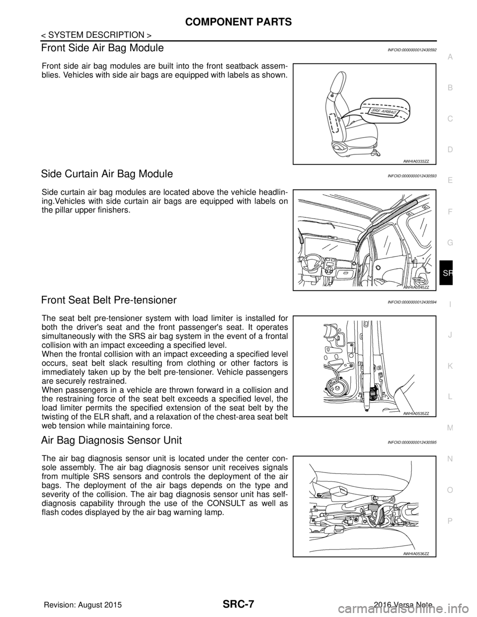
Front Side Air Bag ModuleINFOID:0000000012430592
Front side air bag modules are built into the front seatback assem-
blies. Vehicles with side air bags are equipped with labels as shown.
Side Curtain Air Bag ModuleINFOID:0000000012430593
Side curtain air bag modules are located above the vehicle headlin-
ing.Vehicles with side curtain air bags are equipped with labels on
the pillar upper finishers.
Front Seat Belt Pre-tensionerINFOID:0000000012430594
The seat belt pre-tensioner system with load limiter is installed for
both the driver's seat and the fr ont passenger's seat. It operates
simultaneously with the SRS air bag system in the event of a frontal
collision with an impact exceeding a specified level.
When the frontal collision with an im pact exceeding a specified level
occurs, seat belt slack resulting from clothing or other factors is
immediately taken up by the belt pre-tensioner. Vehicle passengers
are securely restrained.
When passengers in a vehicle are thrown forward in a collision and
the restraining force of the seat belt exceeds a specified level, the
load limiter permits the specified ex tension of the seat belt by the
twisting of the ELR shaft, and a relaxation of the chest-area seat belt
web tension while maintaining force.
Air Bag Diagnosis Sensor UnitINFOID:0000000012430595
The air bag diagnosis sensor unit is located under the center con-
sole assembly. The air bag diagnosis sensor unit receives signals
from multiple SRS sensors and cont rols the deployment of the air
bags. The deployment of the air bags depends on the type and
severity of the collision. The air bag diagnosis sensor unit has self-
diagnosis capability through the us e of the CONSULT as well as
flash codes displayed by the air bag warning lamp.
AWHIA0333ZZ
AWHIA0545ZZ
AWHIA0535ZZ
AWHIA0536ZZ
Revision: August 2015 2016 Versa Note
cardiagn.com
Page 3033 of 3641

SRC-16
< SYSTEM DESCRIPTION >
DIAGNOSIS SYSTEM (AIR BAG)
Trouble Diagnosis with CONSULT
INFOID:0000000012430606
1. Connect CONSULT.
2. DTC is displayed on SELF-DIAG RESULTS.
NOTE:
If a malfunction is not detected on “SELF-DIAG RESULTS [CURRENT]”, but a malfunction is detected during
SRS Operation Check, the following cases may exist:
• “SELF-DIAG [PAST]” memory might not be erased. Refer to SRC-14, "
On Board Diagnosis Function".
• SRS system malfunctions intermittently. Refer to SRC-41, "
InspectionProcedure".
DIAGNOSIS MODE
1. Connect CONSULT.
2. Confirm that zero point reset of OCS is complete.
3. If no DTCs are detected on “SELF-DIAG RESULTS [CURRE NT]”, repair of SRS is completed. Go to step
4.
If any DTCs are detected on “SELF-DIAG RESULT S [CURRENT]”, the malfunction has not been repaired
completely or another malfunction is being detected. Perform SRS Operation Check again. Refer to SRC-
14, "On Board Diagnosis Function".
4. Touch “ERASE”. NOTE:
Touching “ERASE” will clear the SRS memory of the malfunction (“SELF-DIAG [PAST]”). If “SELF-
DIAG [PAST]” is not erased, User Mode may sh ow the previous system malfunction even if the
malfunction has been repaired completely.
5. Check that no malfunction is det ected in “SELF-DIAG [PAST]”.
6. Exit Diagnosis Mode and disconnect the CONSULT.
7. Perform SRS Operation Check. Refer to SRC-14, "
On Board Diagnosis Function".
SRS HISTORY CHECK
1. Check repair history of the SRS. If no repairs have been made, perform SRC-14, "On Board Diagnosis
Function". If repairs have been made, GO TO step 2.
2. Erase ”SELF-DIAG [PAST]” after repair. Refer to SRC-14, "
On Board Diagnosis Function".
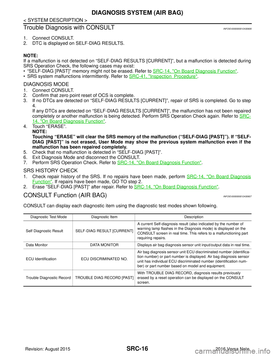
CONSULT Function (AIR BAG)INFOID:0000000012430607
CONSULT can display each diagnostic item using the diagnostic test modes shown following.
Diagnostic Test ModeDiagnostic Item Description
Self Diagnostic Result SEL F-DIAG RESULT [CURRENT]A current Self-diagnosis result (also indicated by the number of
warning lamp flashes in the Diagnosis mode) is displayed on the
CONSULT screen in real time. This refers to a malfunctioning part
requiring repairs.
Data Monitor DATA MONITOR Displays air bag diagnosis sensor unit input/output data in real time.
ECU Identification ECU DISCRIMINATED NO. Air bag diagnosis sensor unit ECU discriminated number (identifica-
tion number) or part number is displayed. Air bag diagnosis sensor
unit has individual ECU discriminated number (identification num-
ber) or part number based on model and equipment.
Trouble Diagnostic Record TR OUBLE DIAG RECORD [PAST] With TROUBLE DIAG RECORD, diagnosis results previously
erased by a reset operation can be displayed on the CONSULT
screen.
Revision: August 2015
2016 Versa Note
cardiagn.com
Page 3034 of 3641

DIAGNOSIS SENSOR UNITSRC-17
< ECU DIAGNOSIS INFORMATION >
C
DE
F
G
I
J
K L
M A
B
SRC
N
O P
ECU DIAGNOSIS INFORMATION
DIAGNOSIS SENSOR UNIT
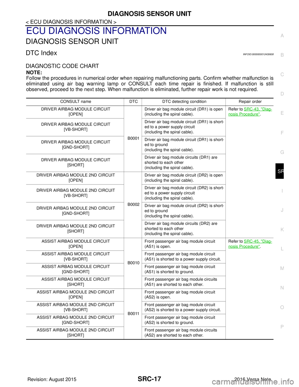
DTC IndexINFOID:0000000012430608
DIAGNOSTIC CODE CHART
NOTE:
Follow the procedures in numerical order when repairi ng malfunctioning parts. Confirm whether malfunction is
eliminated using air bag warning lamp or CONSULT each time repair is finished. If malfunction is still
observed, proceed to the next step. When malfunction is elim inated, further repair work is not required.
CONSULT nameDTCDTC detecting condition Repair order
DRIVER AIRBAG MODULE CIRCUIT [OPEN]
B0001Driver air bag module circuit (DR1) is open
(including the spiral cable).
Refer to SRC-43, "
Diag-
nosis Procedure".
DRIVER AIRBAG MODULE CIRCUIT [VB-SHORT] Driver air bag module circuit (DR1) is short-
ed to a power supply circuit
(including the spiral cable).
DRIVER AIRBAG MODULE CIRCUIT [GND-SHORT] Driver air bag module circuit (DR1) is short-
ed to ground
(including the spiral cable).
DRIVER AIRBAG MODULE CIRCUIT [SHORT] Driver air bag module circuits (DR1) are
shorted to each other
(including the spiral cable).
DRIVER AIRBAG MODULE 2ND CIRCUIT [OPEN]
B0002Driver air bag module circuit (DR2) is open
(including the spiral cable).
DRIVER AIRBAG MODULE 2ND CIRCUIT [VB-SHORT] Driver air bag module circuit (DR2) is short-
ed to a power supply circuit
(including the spiral cable).
DRIVER AIRBAG MODULE 2ND CIRCUIT [GND-SHORT] Driver air bag module circuit (DR2) is short-
ed to ground
(including the spiral cable).
DRIVER AIRBAG MODULE 2ND CIRCUIT [SHORT] Driver air bag module circuits (DR2) are
shorted to each other
(including the spiral cable).
ASSIST AIRBAG MODULE CIRCUIT [OPEN]
B0010Front passenger air bag module circuit
(AS1) is open.
Refer to SRC-45, "
Diag-
nosis Procedure".
ASSIST AIRBAG MODULE CIRCUIT [VB-SHORT] Front passenger air bag module circuit
(AS1) is shorted to a power supply circuit.
ASSIST AIRBAG MODULE CIRCUIT [GND-SHORT] Front passenger air bag module circuit
(AS1) is shorted to ground.
ASSIST AIRBAG MODULE CIRCUIT [SHORT] Front passenger air bag module circuits
(AS1) are shorted to each other.
ASSIST AIRBAG MODULE 2ND CIRCUIT [OPEN]
B0011Front passenger air bag module circuit
(AS2) is open.
ASSIST AIRBAG MODULE 2ND CIRCUIT [VB-SHORT] Front passenger air bag module circuit
(AS2) is shorted to a power supply circuit.
ASSIST AIRBAG MODULE 2ND CIRCUIT [GND-SHORT] Front passenger air bag module circuit
(AS2) is shorted to ground.
ASSIST AIRBAG MODULE 2ND CIRCUIT [SHORT] Front passenger air bag module circuits
(AS2) are shorted to each other.
Revision: August 2015
2016 Versa Note
cardiagn.com