2016 NISSAN NOTE fuel cap
[x] Cancel search: fuel capPage 1871 of 3641
FUEL SYSTEMFL-5
< PERIODIC MAINTENANCE >
C
DE
F
G H
I
J
K L
M A
FL
NP
O
PERIODIC MAINTENANCE
FUEL SYSTEM
InspectionINFOID:0000000012432107
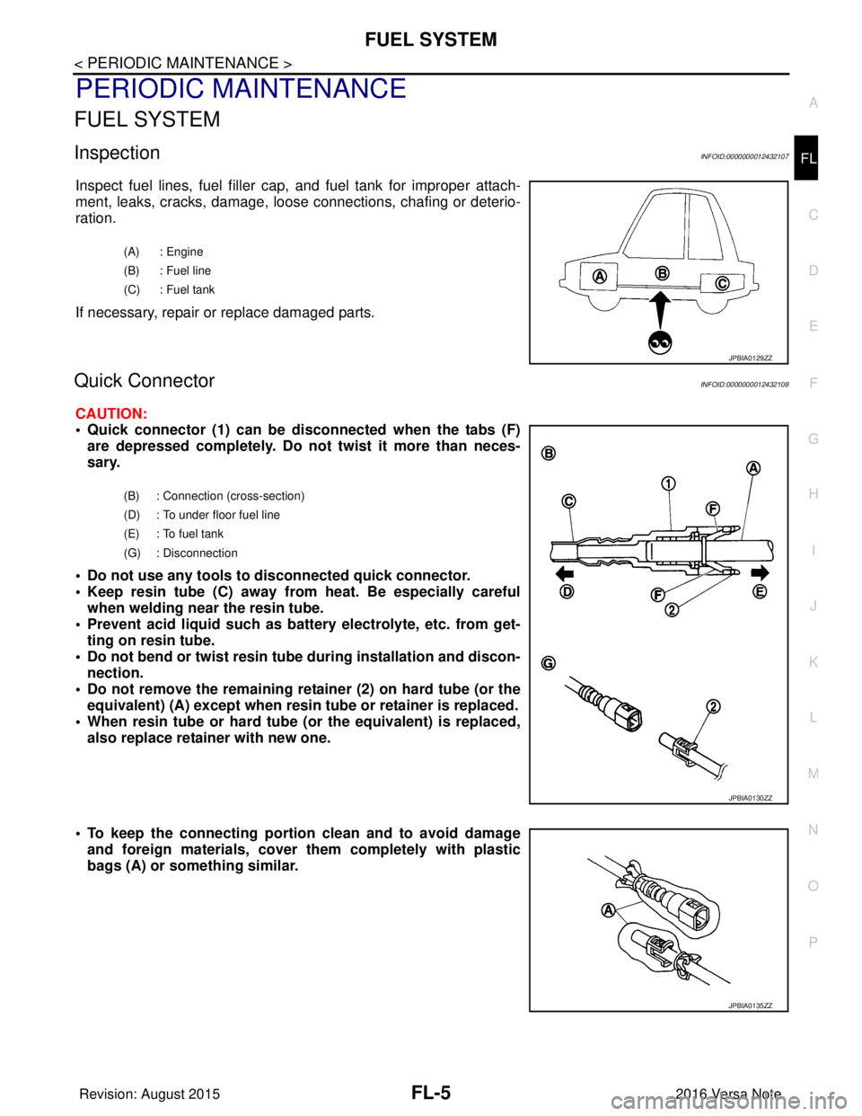
Inspect fuel lines, fuel filler cap,
and fuel tank for improper attach-
ment, leaks, cracks, damage, loos e connections, chafing or deterio-
ration.
If necessary, repair or replace damaged parts.
Quick ConnectorINFOID:0000000012432108
CAUTION:
• Quick connector (1) can be di sconnected when the tabs (F)
are depressed completely. Do not twist it more than neces-
sary.
• Do not use any tools to di sconnected quick connector.
• Keep resin tube (C) away from heat. Be especially careful when welding near the resin tube.
• Prevent acid liquid such as battery electrolyte, etc. from get- ting on resin tube.
• Do not bend or twist resin tube during installation and discon-
nection.
• Do not remove the remaining retainer (2) on hard tube (or the equivalent) (A) except when resin tu be or retainer is replaced.
• When resin tube or hard tube (or the equivalent) is replaced, also replace retainer with new one.
• To keep the connecting portion clean and to avoid damage and foreign materials, cover them completely with plastic
bags (A) or something similar.
(A) : Engine
(B) : Fuel line
(C) : Fuel tank
JPBIA0129ZZ
(B) : Connection (cross-section)
(D) : To under floor fuel line
(E) : To fuel tank
(G) : Disconnection
JPBIA0130ZZ
JPBIA0135ZZ
Revision: August 2015 2016 Versa Note
cardiagn.com
Page 1872 of 3641
FL-6
< REMOVAL AND INSTALLATION >
FUEL LEVEL SENSOR UNIT, FUEL FILTER AND FUEL PUMP ASSEMBLY
REMOVAL AND INSTALLATION
FUEL LEVEL SENSOR UNIT, FUEL FILTER AND FUEL PUMP ASSEMBLY
Exploded ViewINFOID:0000000012432109
Removal and InstallationINFOID:0000000012432110
WARNING:
Read “General Precautions” when wo rking on the fuel system. Refer to FL-2, "
General Precaution".
NOTE:
When removing components such as hoses, tubes/lines, etc. , cap or plug openings to prevent fluid from spill-
ing.
REMOVAL
1. Release the fuel pressure from the fuel lines. Refer to EC-137, "Work Procedure".
2. Disconnect the battery negative terminal. Refer to PG-70, "
Removal and Installation (Battery)".
3. Open fuel filler lid.
4. Open fuel filler cap and release the pressure inside fuel tank.
5. Remove the rear seat cushion. Refer to SE-26, "
SEAT CUSHION : Removal and Installation".
6. Remove the inspection hole cover. NOTE:
Inspection hole cover is held down by an adhesive.
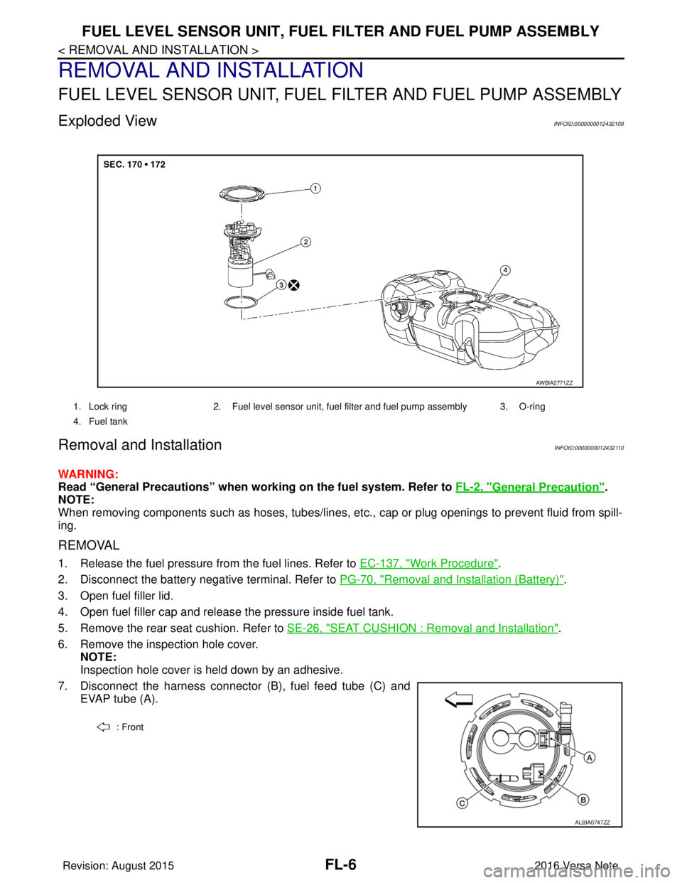
7. Disconnect the harness connector (B), fuel feed tube (C) and EVAP tube (A).
1. Lock ring 2. Fuel level sensor unit, fuel filter and fuel pump assembly 3. O-ring
4. Fuel tank
AWBIA2771ZZ
: Front
ALBIA0747ZZ
Revision: August 2015 2016 Versa Note
cardiagn.com
Page 1876 of 3641
FL-10
< REMOVAL AND INSTALLATION >
FUEL TANK
FUEL TANK
Exploded ViewINFOID:0000000012432112
Removal and InstallationINFOID:0000000012432113
WARNING:
Read “General Precautions” when working on the fuel system. Refer to FL-2, "
General Precaution".
NOTE:
When removing components such as hoses, tubes/lines, etc. , cap or plug openings to prevent fluid from spill-
ing.
REMOVAL
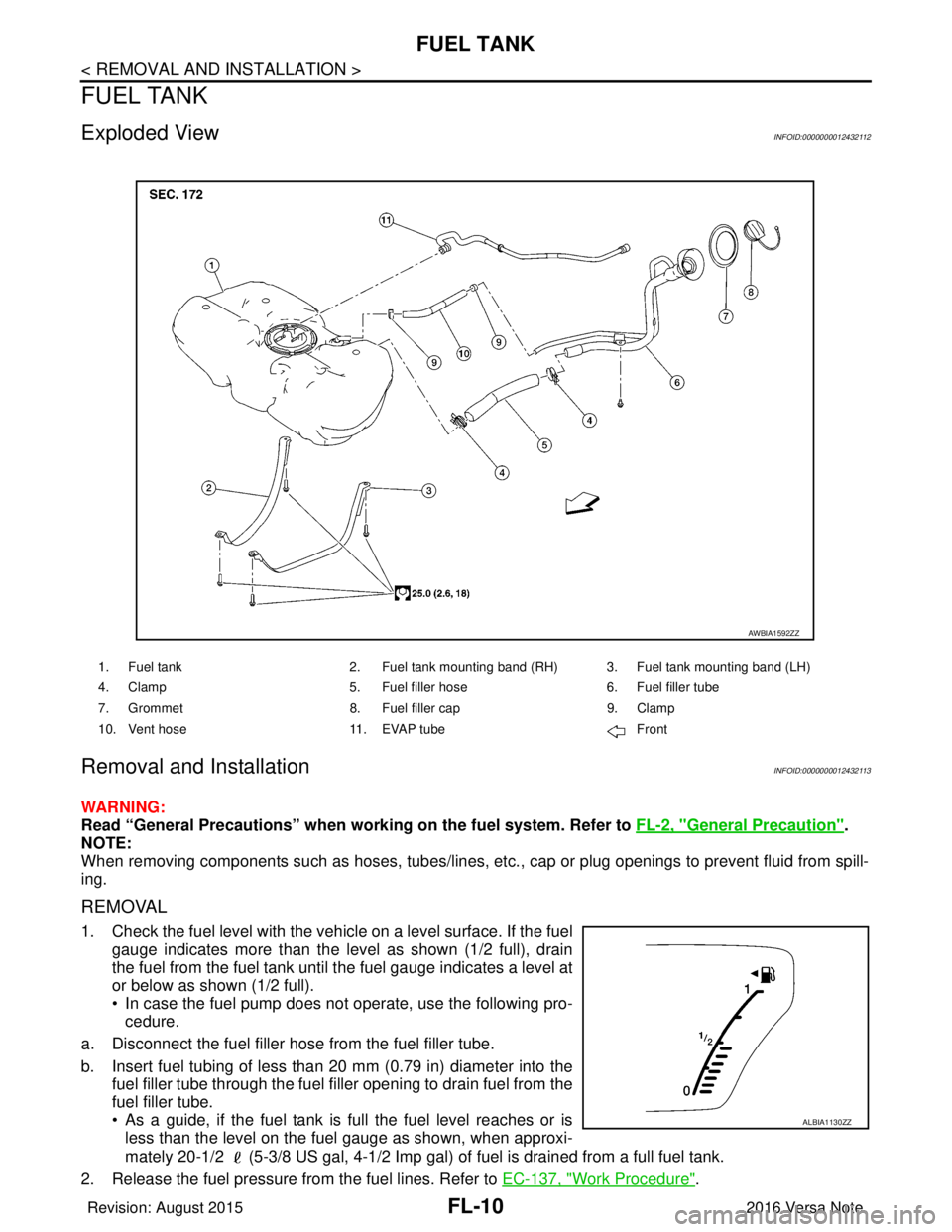
1. Check the fuel level with the vehicle on a level surface. If the fuel gauge indicates more than the level as shown (1/2 full), drain
the fuel from the fuel tank until the fuel gauge indicates a level at
or below as shown (1/2 full).
• In case the fuel pump does not operate, use the following pro-cedure.
a. Disconnect the fuel filler hose from the fuel filler tube.
b. Insert fuel tubing of less than 20 mm (0.79 in) diameter into the fuel filler tube through the fuel f iller opening to drain fuel from the
fuel filler tube.
• As a guide, if the fuel tank is full the fuel level reaches or is less than the level on the fuel gauge as shown, when approxi-
mately 20-1/2 (5-3/8 US gal, 4-1/2 Imp gal) of fuel is drained from a full fuel tank.
2. Release the fuel pressure from the fuel lines. Refer to EC-137, "
Work Procedure".
1. Fuel tank2. Fuel tank mounting band (RH) 3. Fuel tank mounting band (LH)
4. Clamp 5. Fuel filler hose 6. Fuel filler tube
7. Grommet 8. Fuel filler cap 9. Clamp
10. Vent hose 11. EVAP tube Front
AWBIA1592ZZ
ALBIA1130ZZ
Revision: August 2015 2016 Versa Note
cardiagn.com
Page 1877 of 3641
FUEL TANKFL-11
< REMOVAL AND INSTALLATION >
C
DE
F
G H
I
J
K L
M A
FL
NP
O
3. Open fuel filler lid.
4. Open fuel filler cap and release
the pressure inside fuel tank.
5. Remove the rear seat cushion. Refer to SE-26, "
SEAT CUSHION : Removal and Installation".
6. Remove the inspection hole cover. NOTE:
Inspection hole cover is held by an adhesive.
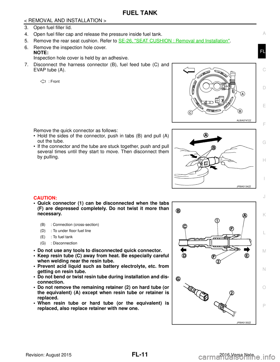
7. Disconnect the harness connector (B), fuel feed tube (C) and
EVAP tube (A).
Remove the quick connector as follows:
• Hold the sides of the connector, push in tabs (B) and pull (A) out the tube.
• If the connector and the tube are stuck together, push and pull several times until they start to move. Then disconnect them
by pulling.
CAUTION:
• Quick connector (1) can be disconnected when the tabs (F) are depressed completely. Do not twist it more than
necessary.
• Do not use any tools to disconnected quick connector.
• Keep resin tube (C) away from heat. Be especially careful when welding near the resin tube.
• Prevent acid liquid such as battery electrolyte, etc. from getting on resin tube.
• Do not bend or twist resin tube during installation and dis- connection.
• Do not remove the remaining retainer (2) on hard tube (or the equivalent) (A) except when resin tube or retainer is
replaced.
• When resin tube or hard tube (or the equivalent) is replaced, also replace retainer with new one.
: Front
ALBIA0747ZZ
JPBIA0134ZZ
(B) : Connection (cross-section)
(D) : To under floor fuel line
(E) : To fuel tank
(G) : Disconnection
JPBIA0130ZZ
Revision: August 2015 2016 Versa Note
cardiagn.com
Page 1888 of 3641
FL-22
< SERVICE DATA AND SPECIFICATIONS (SDS)
SERVICE DATA AND SPECIFICATIONS (SDS)
SERVICE DATA AND SPECIFICATIONS (SDS)
SERVICE DATA AND SPECIFICATIONS (SDS)
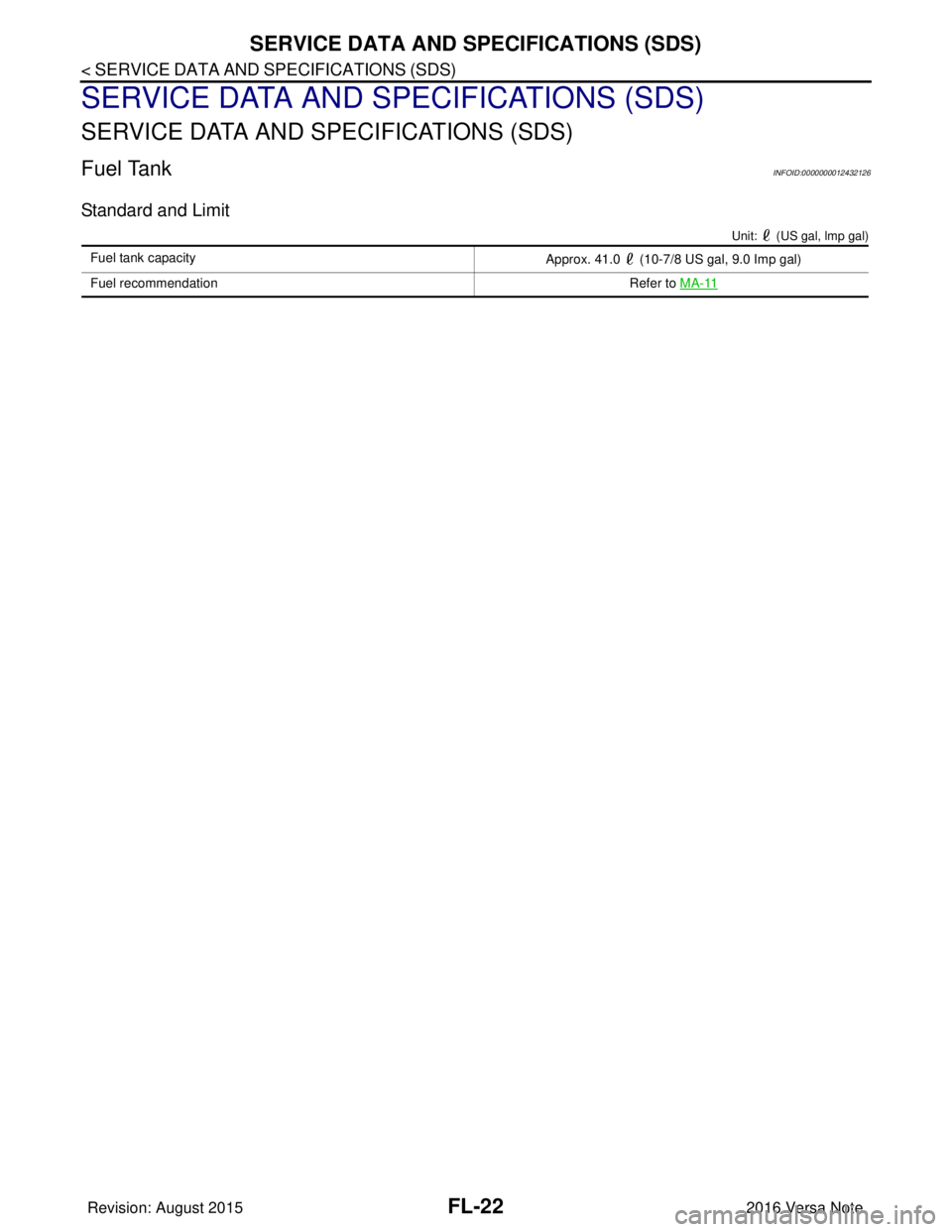
Fuel TankINFOID:0000000012432126
Standard and Limit
Unit: (US gal, lmp gal)
Fuel tank capacityApprox. 41.0 (10-7/8 US gal, 9.0 Imp gal)
Fuel recommendation Refer to MA-11
Revision: August 2015 2016 Versa Note
cardiagn.com
Page 1912 of 3641
GI-24
< PRECAUTION >
PRECAUTIONS
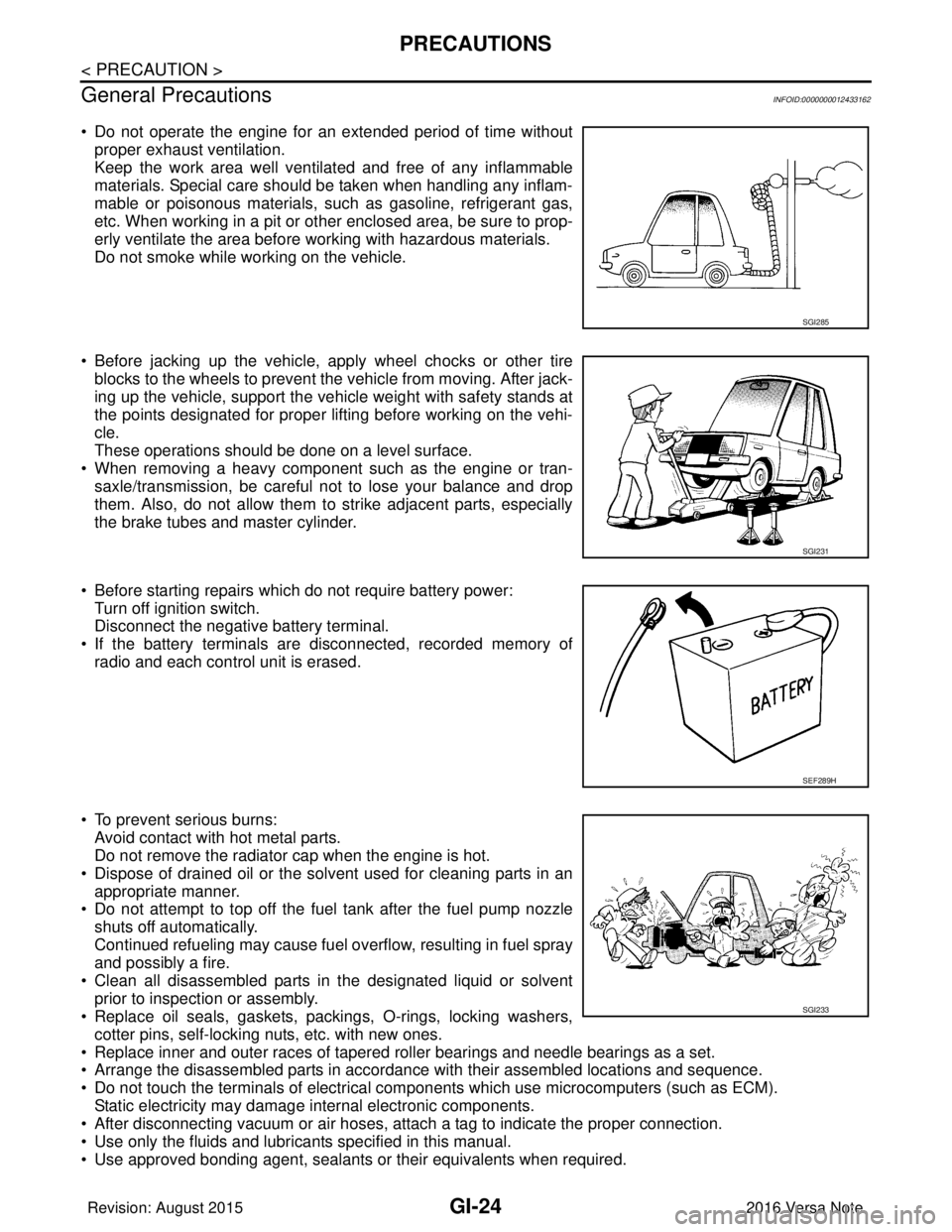
General Precautions
INFOID:0000000012433162
• Do not operate the engine for an extended period of time without proper exhaust ventilation.
Keep the work area well ventilated and free of any inflammable
materials. Special care should be taken when handling any inflam-
mable or poisonous materials, such as gasoline, refrigerant gas,
etc. When working in a pit or other enclosed area, be sure to prop-
erly ventilate the area before working with hazardous materials.
Do not smoke while working on the vehicle.
• Before jacking up the vehicle, apply wheel chocks or other tire blocks to the wheels to prevent the vehicle from moving. After jack-
ing up the vehicle, support the vehicle weight with safety stands at
the points designated for proper lifting before working on the vehi-
cle.
These operations should be done on a level surface.
• When removing a heavy component such as the engine or tran- saxle/transmission, be careful not to lose your balance and drop
them. Also, do not allow them to strike adjacent parts, especially
the brake tubes and master cylinder.
• Before starting repairs which do not require battery power: Turn off ignition switch.
Disconnect the negative battery terminal.
• If the battery terminals are disconnected, recorded memory of radio and each control unit is erased.
• To prevent serious burns: Avoid contact with hot metal parts.
Do not remove the radiator cap when the engine is hot.
• Dispose of drained oil or the solvent used for cleaning parts in an appropriate manner.
• Do not attempt to top off the fuel tank after the fuel pump nozzle
shuts off automatically.
Continued refueling may cause fuel overflow, resulting in fuel spray
and possibly a fire.
• Clean all disassembled parts in the designated liquid or solvent prior to inspection or assembly.
• Replace oil seals, gaskets, packings, O-rings, locking washers,
cotter pins, self-locking nuts, etc. with new ones.
• Replace inner and outer races of tapered roller bearings and needle bearings as a set.
• Arrange the disassembled parts in accordance with their assembled locations and sequence.
• Do not touch the terminals of electrical com ponents which use microcomputers (such as ECM).
Static electricity may damage internal electronic components.
• After disconnecting vacuum or air hoses, atta ch a tag to indicate the proper connection.
• Use only the fluids and lubricants specified in this manual.
• Use approved bonding agent, sealants or their equivalents when required.
SGI285
SGI231
SEF289H
SGI233
Revision: August 2015 2016 Versa Note
cardiagn.com
Page 2218 of 3641
![NISSAN NOTE 2016 Service Repair Manual LAN-30
< SYSTEM DESCRIPTION >[CAN]
SYSTEM
CAN COMMUNICATION SYSTEM : CA N Communication Signal Chart
INFOID:0000000012433349
Refer to LAN-15, "How to Use CAN Communication Signal Chart" for how to use NISSAN NOTE 2016 Service Repair Manual LAN-30
< SYSTEM DESCRIPTION >[CAN]
SYSTEM
CAN COMMUNICATION SYSTEM : CA N Communication Signal Chart
INFOID:0000000012433349
Refer to LAN-15, "How to Use CAN Communication Signal Chart" for how to use](/manual-img/5/57363/w960_57363-2217.png)
LAN-30
< SYSTEM DESCRIPTION >[CAN]
SYSTEM
CAN COMMUNICATION SYSTEM : CA N Communication Signal Chart
INFOID:0000000012433349
Refer to LAN-15, "How to Use CAN Communication Signal Chart" for how to use CAN communication signal
chart.
NOTE:
• Refer to LAN-21, "
Abbreviation List" for the abbreviations of the connecting units.
• The air bag diagnosis sensor unit and AV control unit uses CAN communication only for communicating with
the diagnostic tool (not with other connected control units).
T: Transmit R: Receive
NAVI switches Side camera LH
With navigation system With around view monitor system
ALMIA0821ZZ
Signal nameECM
ABS
IPDM-E TCM
AV M EPS
M&A
STRG BCM
Accelerator pedal position signal T RR
A/C compressor request signal TR
Closed throttle position signal TR
Cooling fan speed request signal TR
ECO pedal guide signal TR
Engine and CVT integrated control signal TR
RT
Engine coolant temperature signal TR R R
Engine speed signal T RR R
Engine status signal T RR R
Fuel filler cap warning display signal TR
N idle instruction signal TR
RT
Malfunctioning indicator lamp signal TR
RT
Oil pressure warning lamp signal TR
Power generation command value signal TR
ABS warning lamp signal TR
VDC warning lamp signal TR
VDC OFF indicator lamp signal TR
Revision: August 2015 2016 Versa Note
cardiagn.com
Page 2219 of 3641
![NISSAN NOTE 2016 Service Repair Manual LAN
SYSTEMLAN-31
< SYSTEM DESCRIPTION > [CAN]
C
D
E
F
G H
I
J
K L
B A
O P
N
Vehicle speed signal (ABS)
TR R R R R
Brake warning lamp signal TR
Detention switch signal TR
Front wiper stop position sign NISSAN NOTE 2016 Service Repair Manual LAN
SYSTEMLAN-31
< SYSTEM DESCRIPTION > [CAN]
C
D
E
F
G H
I
J
K L
B A
O P
N
Vehicle speed signal (ABS)
TR R R R R
Brake warning lamp signal TR
Detention switch signal TR
Front wiper stop position sign](/manual-img/5/57363/w960_57363-2218.png)
LAN
SYSTEMLAN-31
< SYSTEM DESCRIPTION > [CAN]
C
D
E
F
G H
I
J
K L
B A
O P
N
Vehicle speed signal (ABS)
TR R R R R
Brake warning lamp signal TR
Detention switch signal TR
Front wiper stop position signal TR
High beam status signal RT
Ignition switch ON signal TR
RT
Interlock/PNP switch signal TR
RT
Low beam status signal RT
Push-button ignition switch status signal TR
OD OFF indicator signal RT
RT
Starter control relay signal TR
RT
Starter relay status signal TR
RT
Sleep-ready signal TR
TR
Wake up signal TR
Input shaft revolution signal RT
O/D OFF indicator signal TR
Output shaft revolution signal RT
Shift position signal RT RR
Target gear ratio signal RT
EPS warning lamp signal TR
Overdrive control switch signal RT
Fuel filler cap warning reset signal RT
O/D OFF switch signal RT
Odometer signal TR
Vehicle speed signal (Meter) RR TR
Wake up signal TR
Steering angle sensor signal RR T
A/C ON signal R T
Blower fan ON signal R T
Buzzer output signal RT
Dimmer signal RT
Door switch signal RRT
Engine start operation indicator lamp signal RT
Front wiper request signal RT
High beam request signal RRT
Key warning lamp signal RT
Low beam request signal RRT
Signal name
ECM
ABS
IPDM-E
TCMAV M
EPS
M&A
STRG
BCM
Revision: August 2015 2016 Versa Note
cardiagn.com