2016 NISSAN NOTE window
[x] Cancel search: windowPage 368 of 3641
![NISSAN NOTE 2016 Service Repair Manual BCS
BCM
BCS-107
< ECU DIAGNOSIS INFORMATION > [WITHOUT INTELLIGENT KEY SYSTEM]
C
D
E
F
G H
I
J
K L
B A
O P
N
10
(G) Ground
Rear defogger sw
signal Input
Rear window
defogger switch OFF
Battery volta NISSAN NOTE 2016 Service Repair Manual BCS
BCM
BCS-107
< ECU DIAGNOSIS INFORMATION > [WITHOUT INTELLIGENT KEY SYSTEM]
C
D
E
F
G H
I
J
K L
B A
O P
N
10
(G) Ground
Rear defogger sw
signal Input
Rear window
defogger switch OFF
Battery volta](/manual-img/5/57363/w960_57363-367.png)
BCS
BCM
BCS-107
< ECU DIAGNOSIS INFORMATION > [WITHOUT INTELLIGENT KEY SYSTEM]
C
D
E
F
G H
I
J
K L
B A
O P
N
10
(G) Ground
Rear defogger sw
signal Input
Rear window
defogger switch OFF
Battery voltage
ON 0 V
11
(L) Ground ACC switch signal Input Ignition switch OFF
0 V
ACC or ON Battery voltage
12
(GR) Ground Central door lock sw
signal InputDoor lock and
unlock switch N position
1.0 - 1.5 V
LOCK position 0 V
13
(BR) Ground Central door unlock
sw signal InputDoor lock and
unlock switch N position
1.0 - 1.5 V
UNLOCK position 0 V
18
(V) Ground Keyless gnd signal Input Ignition switch ON
0 V
19
(LG) Ground
Keyless tuner power
supply Input
Ignition switch
OFF Key inserted into ignition
key cylinder
0 V
Key removed from ignition
key cylinder
(Any door open) 5 V
Key removed from ignition
key cylinder
(Any door closed)
Terminal No.
(Wire color) Description
Condition Va l u e
(Approx.)
Signal name Input/
Output
+ −
JPMIA0012GB
JPMIA0012GB
JPMIA0338JP
Revision: August 2015 2016 Versa Note
cardiagn.com
Page 373 of 3641
![NISSAN NOTE 2016 Service Repair Manual BCS-112
< ECU DIAGNOSIS INFORMATION >[WITHOUT INTELLIGENT KEY SYSTEM]
BCM
36
(LG) Ground Output 1 signal Output
Combination
switchOFF
7.0 - 8.0 V
FR WASHER
1.2 V
FR WIPER LOW
TURN LH
TURN RH
37
(Y) G NISSAN NOTE 2016 Service Repair Manual BCS-112
< ECU DIAGNOSIS INFORMATION >[WITHOUT INTELLIGENT KEY SYSTEM]
BCM
36
(LG) Ground Output 1 signal Output
Combination
switchOFF
7.0 - 8.0 V
FR WASHER
1.2 V
FR WIPER LOW
TURN LH
TURN RH
37
(Y) G](/manual-img/5/57363/w960_57363-372.png)
BCS-112
< ECU DIAGNOSIS INFORMATION >[WITHOUT INTELLIGENT KEY SYSTEM]
BCM
36
(LG) Ground Output 1 signal Output
Combination
switchOFF
7.0 - 8.0 V
FR WASHER
1.2 V
FR WIPER LOW
TURN LH
TURN RH
37
(Y) Ground Key sw signal Input Ignition switch Ignition key inserted into
ignition key cylinder
Battery voltage
Ignition key removed from
ignition key cylinder 0 V
38
(O) Ground Ign sw signal
Input Ignition switchOFF or ACC
0 V
ON or START Battery voltage
39
(L) Ground CAN high
Input/
Output ——
40
(P) Ground CAN low Input/
Output ——
41
(G) Ground Door unlock output
(DR) signal OutputFront door lock
actuator LH Actuated to UNLOCK po-
sition
Battery voltage
Other than actuated to
UNLOCK position 0 V
42
(Y) Ground Battery (FUSE) Input Ignition switch OFF
Battery voltage
43
(W) Ground Battery saver output
signal
OutputInterior room lamp battery saver activated
0 V
Interior room lamp battery saver not activat-
ed Battery voltage
44
(GR) Ground Rear defogger relay
output signal InputRear window
defogger switch OFF
Battery voltage
ON 0 – 0.5 V
45
(R) Ground Room lamp output
signal OutputInterior room
lamp or map
lamp OFF
Battery voltage
ON Battery voltage
DOOR 0 – 1 V
48
(L) Ground A/C indicator
Input— —
50
(G) Ground Battery (F/L)
Input Ignition switch OFF Battery voltage
52
(L) Ground Power window pow-
er supply (RAP) sig-
nal Output Ignition switch ON
Battery voltage
Te r m i n a l N o .
(Wire color) Description
Condition Va l u e
(Approx. )
Sign al
name Input/
Output
+ −
PKIB4960J
PKIB4958J
Revision: August 2015 2016 Versa Note
cardiagn.com
Page 652 of 3641

DEF-1
DRIVER CONTROLS
C
DE
F
G H
I
J
K
M
SECTION DEF
A
B
DEF
N
O P
CONTENTS
DEFOGGER
PRECAUTION ....... ........................................3
PRECAUTIONS .............................................. .....3
Precaution for Supplemental Restraint System
(SRS) "AIR BAG" and "SEAT BELT PRE-TEN-
SIONER" ............................................................. ......
3
SYSTEM DESCRIPTION ..............................4
COMPONENT PARTS ................................... .....4
Component Parts Location .................................. ......4
Rear window defogger ..............................................5
Door mirror defogger .................................................5
SYSTEM ..............................................................6
System Description ............................................. ......6
DIAGNOSIS SYSTEM (BCM) (WITH INTELLI-
GENT KEY SYSTEM) ..........................................
7
COMMON ITEM ..................................................... ......7
COMMON ITEM : CONSULT Function (BCM -
COMMON ITEM) .......................................................
7
REAR DEFOGGER ............................................... ......8
REAR DEFOGGER : CONSULT Function (BCM -
REAR DEFOGGER) ........................................... ......
8
DIAGNOSIS SYSTEM (BCM) (WITHOUT IN-
TELLIGENT KEY SYSTEM) ................................
9
COMMON ITEM ..................................................... ......9
COMMON ITEM : CONSULT Function (BCM -
COMMON ITEM) .......................................................
9
REAR DEFOGGER ............................................... ....10
REAR DEFOGGER : CONSULT Function (BCM -
REAR DEFOGGER) ........................................... ....
10
ECU DIAGNOSIS INFORMATION ..............11
BCM ................................................................ ....11
List of ECU Reference ........................................ ....11
WIRING DIAGRAM ......................................12
REAR WINDOW DE FOGGER SYSTEM ..........12
Wiring Diagram .................................................... ....12
BASIC INSPECTION ...................................17
DIAGNOSIS AND REPAIR WORK FLOW .......17
Work Flow ............................................................ ....17
DTC/CIRCUIT DIAGNOSIS .........................20
REAR WINDOW DEFOGGER SWITCH ...........20
Description ........................................................... ....20
Component Function Check ....................................20
Diagnosis Procedure ...............................................20
Component Inspection .............................................21
REAR WINDOW DEFOGGER RELAY .............22
Description ...............................................................22
Component Function Check ....................................22
Diagnosis Procedure ...............................................22
Component Inspection .............................................23
REAR WINDOW DEFOGGER POWER SUP-
PLY AND GROUND CIRCUIT ..........................
24
Description ...............................................................24
Component Function Check ....................................24
Diagnosis Procedure ...............................................24
Component Inspection .............................................25
DRIVER SIDE DOOR MIRROR DEFOGGER ...26
Description ...............................................................26
Component Function Check ....................................26
Diagnosis Procedure ...............................................26
Component Inspection .............................................27
PASSENGER SIDE DOOR MIRROR DEFOG-
GER ...................................................................
28
Description ...............................................................28
Component Function Check ....................................28
Diagnosis Procedure ...............................................28
Revision: August 2015 2016 Versa Note
cardiagn.com
Page 653 of 3641

DEF-2
Component Inspection ............................................29
SYMPTOM DIAGNOSIS .............................30
REAR WINDOW DEFOGGER AND DOOR
MIRROR DEFOGGER DO NOT OPERATE. .. ...
30
Diagnosis Procedure ........................................... ...30
REAR WINDOW DEFOGGER DOES NOT
OPERATE BUT BOTH OF DOOR MIRROR
DEFOGGER OPERATE. ...................................
31
Diagnosis Procedure ........................................... ...31
BOTH DOORS MIRROR DEFOGGER DON’T
OPERATE BUT REAR WINDOW DEFOG-
GER OPERATES ...............................................
32
Diagnosis Procedure ........................................... ...32
DRIVER SIDE DOOR MIRROR DEFOGGER
DOES NOT OPERATE. .....................................
33
Diagnosis Procedure ............................................ ...33
PASSENGER SIDE DOOR MIRROR DEFOG-
GER DOES NOT OPERATE. ............................
34
Diagnosis Procedure ............................................ ...34
REAR WINDOW DEFOGGER SWITCH DOES
NOT LIGHT, BUT REAR WINDOW DEFOG-
GER OPERATES ...............................................
35
Diagnosis Procedure ............................................ ...35
REMOVAL AND INSTALLATION ..............36
FILAMENT ...................................................... ...36
Inspection and Repair .......................................... ...36
CONDENSER ....................................................38
Removal and Installation .........................................38
Revision: August 2015 2016 Versa Note
cardiagn.com
Page 655 of 3641

DEF-4
< SYSTEM DESCRIPTION >
COMPONENT PARTS
SYSTEM DESCRIPTION
COMPONENT PARTS
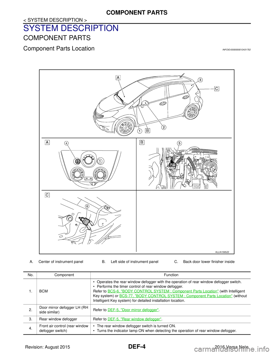
Component Parts LocationINFOID:0000000012431752
A. Center of instrument panel B. Left side of instrument panel C. Back door lower finisher inside
ALLIA1565ZZ
No.Component Function
1. BCM • Operates the rear window defogger with the operation of rear window defogger switch.
• Performs the timer control of rear window defogger.
Refer to BCS-6, "
BODY CONTROL SYSTEM : Co
mponent Parts Location" (with Intelligent
Key system) or BCS-77, "
BODY CONTROL SYSTEM : Co mponent Parts Location" (without
Intelligent Key system) for detailed installation location.
2. Door mirror defogger LH (RH
side similar)
Refer to DEF-5, "
Door mirror defogger".
3. Rear window defogger Refer to DEF-5, "
Rear window defogger".
4. Front air control (rear window
defogger switch) • The rear window defogger switch is turned ON.
• Turns the indicator lamp ON when detecting the operation of rear window defogger.
Revision: August 2015
2016 Versa Note
cardiagn.com
Page 656 of 3641

COMPONENT PARTSDEF-5
< SYSTEM DESCRIPTION >
C
DE
F
G H
I
J
K
M A
B
DEF
N
O P
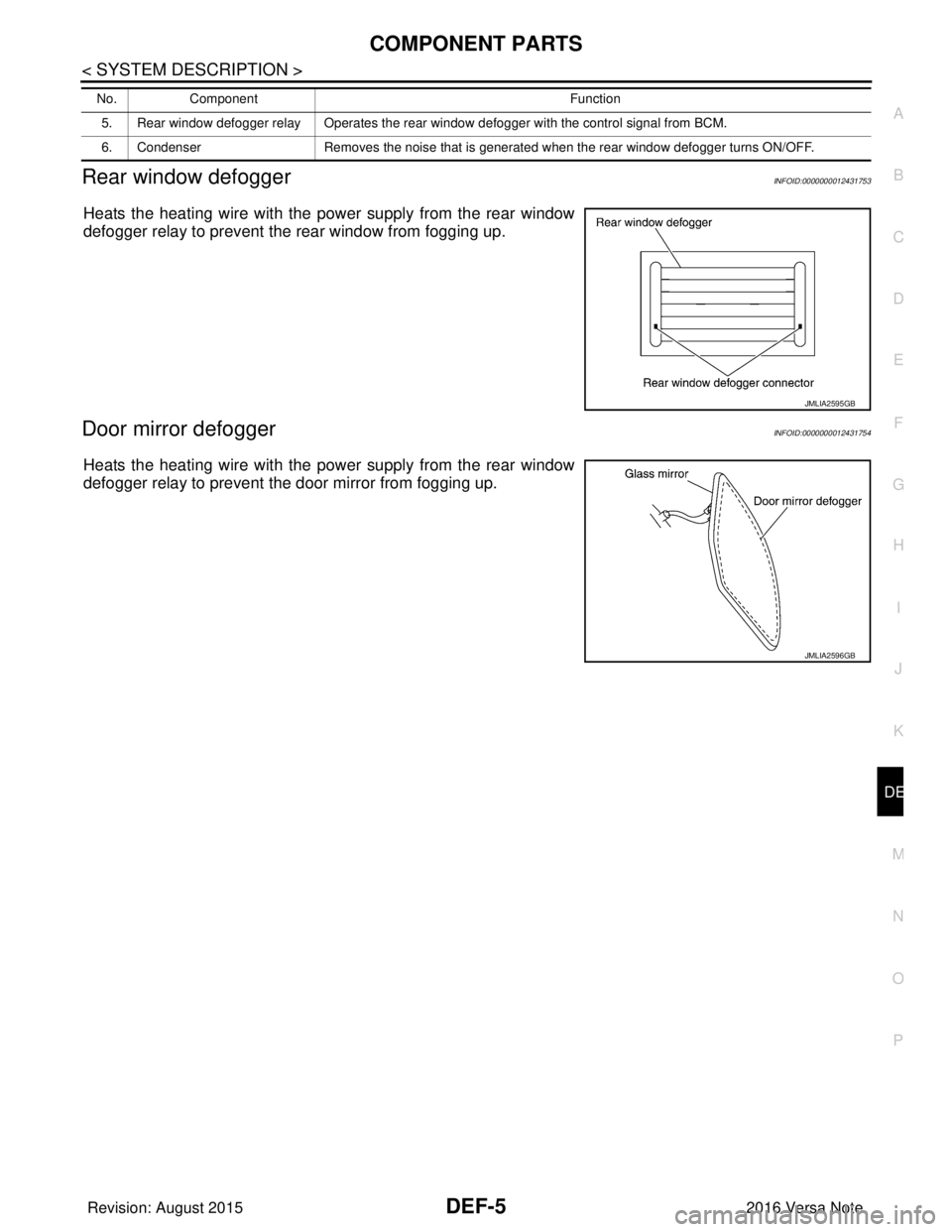
Rear window defoggerINFOID:0000000012431753
Heats the heating wire with the pow er supply from the rear window
defogger relay to prevent the rear window from fogging up.
Door mirror defoggerINFOID:0000000012431754
Heats the heating wire with the pow er supply from the rear window
defogger relay to prevent the door mirror from fogging up.
5. Rear window defogger relay Operates the rear window defogger with the control signal from BCM.
6. Condenser Removes the noise that is generated when the rear window defogger turns ON/OFF.
No.
Component Function
JMLIA2595GB
JMLIA2596GB
Revision: August 2015 2016 Versa Note
cardiagn.com
Page 657 of 3641

DEF-6
< SYSTEM DESCRIPTION >
SYSTEM
SYSTEM
System DescriptionINFOID:0000000012431755
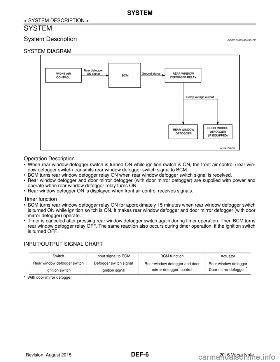
SYSTEM DIAGRAM
Operation Description
• When rear window defogger switch is turned ON while ignition switch is ON, the front air control (rear win-dow defogger switch) transmits rear window defogger switch signal to BCM.
• BCM turns rear window defogger relay ON when rear window defogger switch signal is received.
• Rear window defogger and door mirror defogger (with door mirror defogger) are supplied with power and operate when rear window defogger relay turns ON.
• Rear window defogger ON is displayed when front air control receives signals.
Timer function
• BCM turns rear window defogger relay ON for appr oximately 15 minutes when rear window defogger switch
is turned ON while ignition switch is ON. It makes rear window defogger and door mirror defogger (with door
mirror defogger) operate.
• Timer is canceled after pressing rear window defogger switch again during timer operation. Then BCM turns rear window defogger relay OFF. The same reaction also occurs during timer operation, if the ignition switch
is turned OFF.
INPUT/OUTPUT SIGNAL CHART
*: With door mirror defogger
ALLIA1028GB
Switch Input signal to BCM BCM functionActuator
Rear window defogger switch Defogger switch signal Rear window defogger and door
mirror defogger
* control Rear window defogger
Door mirror defogger *Ignition switch Ignition signal
Revision: August 2015 2016 Versa Note
cardiagn.com
Page 658 of 3641

DIAGNOSIS SYSTEM (BCM) (WITH INTELLIGENT KEY SYSTEM)
DEF-7
< SYSTEM DESCRIPTION >
C
D E
F
G H
I
J
K
M A
B
DEF
N
O P
DIAGNOSIS SYSTEM (BCM) (WIT H INTELLIGENT KEY SYSTEM)
COMMON ITEM
COMMON ITEM : CONSULT Function (BCM - COMMON ITEM)INFOID:0000000012542306
APPLICATION ITEM
CONSULT performs the following functions via CAN communication with BCM.
SYSTEM APPLICATION
BCM can perform the following functions.
Direct Diagnostic Mode Description
ECU Identification The BCM part number is displayed.
Self Diagnostic Result The BCM self diagnostic results are displayed.
Data Monitor The BCM input/output data is displayed in real time.
Active Test The BCM activates outputs to test components.
Work support The settings for BCM functions can be changed.
Configuration • The vehicle specification can be read and saved.
• The vehicle specification can be written when replacing BCM.
CAN DIAG SUPPORT MNTR The result of transmit/receive diagnosis of CAN communication is displayed.
System Sub System Direct Diagnostic Mode
ECU Identification
Self Diagnostic Result
Data Monitor
Active Test
Work support
Configuration
CAN DIAG SUPPORT MNTR
Door lock
DOOR LOCK ×××
Rear window defogger REAR DEFOGGER ××
Warning chime BUZZER ××
Interior room lamp timer INT LAMP ×××
Exterior lamp HEAD LAMP ×××
Wiper and washer WIPER ×××
Turn signal and hazard warning lamps FLASHER ×××
Air conditioner AIR CONDITIONER ×
Intelligent Key system INTELLIGENT KEY ××××
Combination switch COMB SW ×
BCM BCM× × ×××
Immobilizer IMMU ××××
Interior room lamp battery saver BATTERY SAVER ×××
Vehicle security system THEFT ALM ××
RAP system RETAINED PWR ×
Signal buffer system SIGNAL BUFFER ×
TPMS AIR PRESSURE MONITOR ××××
Panic alarm system PANIC ALARM ×
Revision: August 2015 2016 Versa Note
cardiagn.com