2016 NISSAN NOTE wheel bolt torque
[x] Cancel search: wheel bolt torquePage 1835 of 3641
FAX-18
< REMOVAL AND INSTALLATION >
FRONT DRIVE SHAFT BOOT
• Check each mating surface for water and foreign matter. If there is any water or foreign matter,
clean the mating surface.
17. Install the transverse link to the steering knuckle with the nut and bolt. Refer to FSU-10, "
Exploded View".
18. Hold the wheel hub using a Tool. Tighten the wheel hub lock nut. CAUTION:
• Since the drive shaft is assembled by press-fitting, use a torque wrench to tighten the wheel hub
lock nut. Do not use a power tool.
• Too much torque causes axle noise. Too little torque causes wheel bearing looseness. Tighten the wheel hub lock nut to the specification.
19. Install the cotter pin. Securely bend the cotter pin to prevent rattles. CAUTION:
Do not reuse the cotter pin.
20. Install the wheel sensor, the wheel sensor bolt, and the wheel sensor harness. Refer to BRC-140,
"FRONT WHEEL SENSOR : Removal and Installation".
21. Align the matching marks on the disc brake roto r and on the wheel hub. Install the disc brake rotor.
CAUTION:
Do not drop the disc brake rotor.
22. Remove the wire from the brake caliper. Install the brake caliper and the brake caliper torque member
bolts. Refer to BR-37, "
BRAKE CALIPER ASSEMBLY : Removal and Installation".
CAUTION:
Do not twist the brake hose.
23. Install the wheel and tire. Refer to WT-48, "
Removal and Installation".
24. Complete the inspection. Refer to FAX-18, "
Inspection".
TRANSAXLE SIDE
TRANSAXLE SIDE : Removal and InstallationINFOID:0000000012431896
Remove boot after drive shaft is removed from the vehicle.
• For drive shaft removal and installation, refer to FAX-19, "
Removal and Installation".
• For drive shaft disassembly and assembly, refer to FAX-22, "
Disassembly and Assembly".
InspectionINFOID:0000000012431897
INSPECTION AFTER INSTALLATION
1. Check the wheel sensor harness to be sure the connectors are fully seated.
2. Check the wheel alignment. Refer to FSU-7, "
Inspection".
Tool number : KV4010104000 ( — )
Revision: August 2015
2016 Versa Note
cardiagn.com
Page 1854 of 3641
FRONT COIL SPRING AND STRUTFSU-9
< REMOVAL AND INSTALLATION >
C
DF
G H
I
J
K L
M A
B
FSU
N
O P
REMOVAL AND INSTALLATION
FRONT COIL SPRING AND STRUT
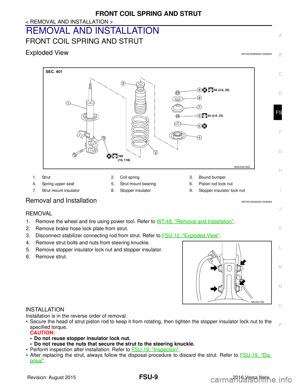
Exploded ViewINFOID:0000000012430303
Removal and InstallationINFOID:0000000012430304
REMOVAL
1. Remove the wheel and tire using power tool. Refer to WT-48, "Removal and Installation".
2. Remove brake hose lock plate from strut.
3. Disconnect stabilizer connecting rod from strut. Refer to FSU-12, "
Exploded View".
4. Remove strut bolts and nuts from steering knuckle.
5. Remove stopper insulator lock nut and stopper insulator.
6. Remove strut.
INSTALLATION
Installation is in the reverse order of removal.
• Secure the head of strut piston rod to keep it from rotating, then tighten the stopper insulator lock nut to the specified torque.
CAUTION:
• Do not reuse stopper insulator lock nut.
• Do not reuse the nuts that secure the strut to the steering knuckle.
• Perform inspection after installation. Refer to FSU-19, "
Inspection".
• After replacing the strut, always follow the dis posal procedure to discard the strut. Refer to FSU-19, "
Dis-
posal".
1. Strut2. Coil spring3. Bound bumper
4. Spring upper seat 5. Strut mount bearing6. Piston rod lock nut
7. Strut mount insulator 8. Stopper insulator9. Stopper insulator lock nut
AWEIA0418ZZ
WEIA0179E
Revision: August 2015 2016 Versa Note
cardiagn.com
Page 1855 of 3641
FSU-10
< REMOVAL AND INSTALLATION >
TRANSVERSE LINK
TRANSVERSE LINK
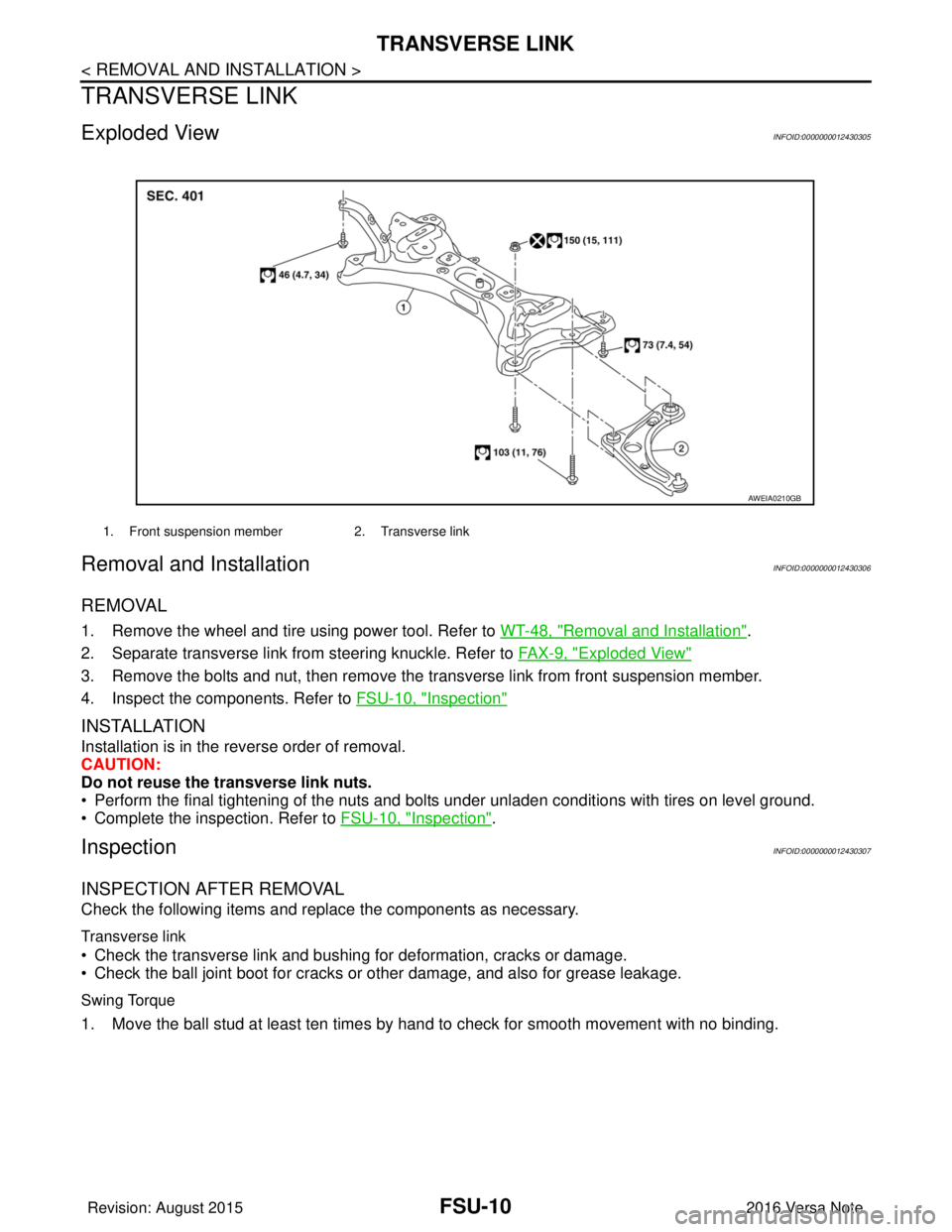
Exploded ViewINFOID:0000000012430305
Removal and InstallationINFOID:0000000012430306
REMOVAL
1. Remove the wheel and tire using power tool. Refer to WT-48, "Removal and Installation".
2. Separate transverse link from steering knuckle. Refer to FA X - 9 , "
Exploded View"
3. Remove the bolts and nut, then remove the transverse link from front suspension member.
4. Inspect the components. Refer to FSU-10, "
Inspection"
INSTALLATION
Installation is in the reverse order of removal.
CAUTION:
Do not reuse the transverse link nuts.
• Perform the final tightening of the nuts and bolts under unladen conditions with tires on level ground.
• Complete the inspection. Refer to FSU-10, "
Inspection".
InspectionINFOID:0000000012430307
INSPECTION AFTER REMOVAL
Check the following items and replace the components as necessary.
Transverse link
• Check the transverse link and bushing for deformation, cracks or damage.
• Check the ball joint boot for cracks or other damage, and also for grease leakage.
Swing Torque
1. Move the ball stud at least ten times by hand to check for smooth movement with no binding.
1. Front suspension member2. Transverse link
AWEIA0210GB
Revision: August 2015 2016 Versa Note
cardiagn.com
Page 1858 of 3641
FRONT STABILIZERFSU-13
< REMOVAL AND INSTALLATION >
C
DF
G H
I
J
K L
M A
B
FSU
N
O P
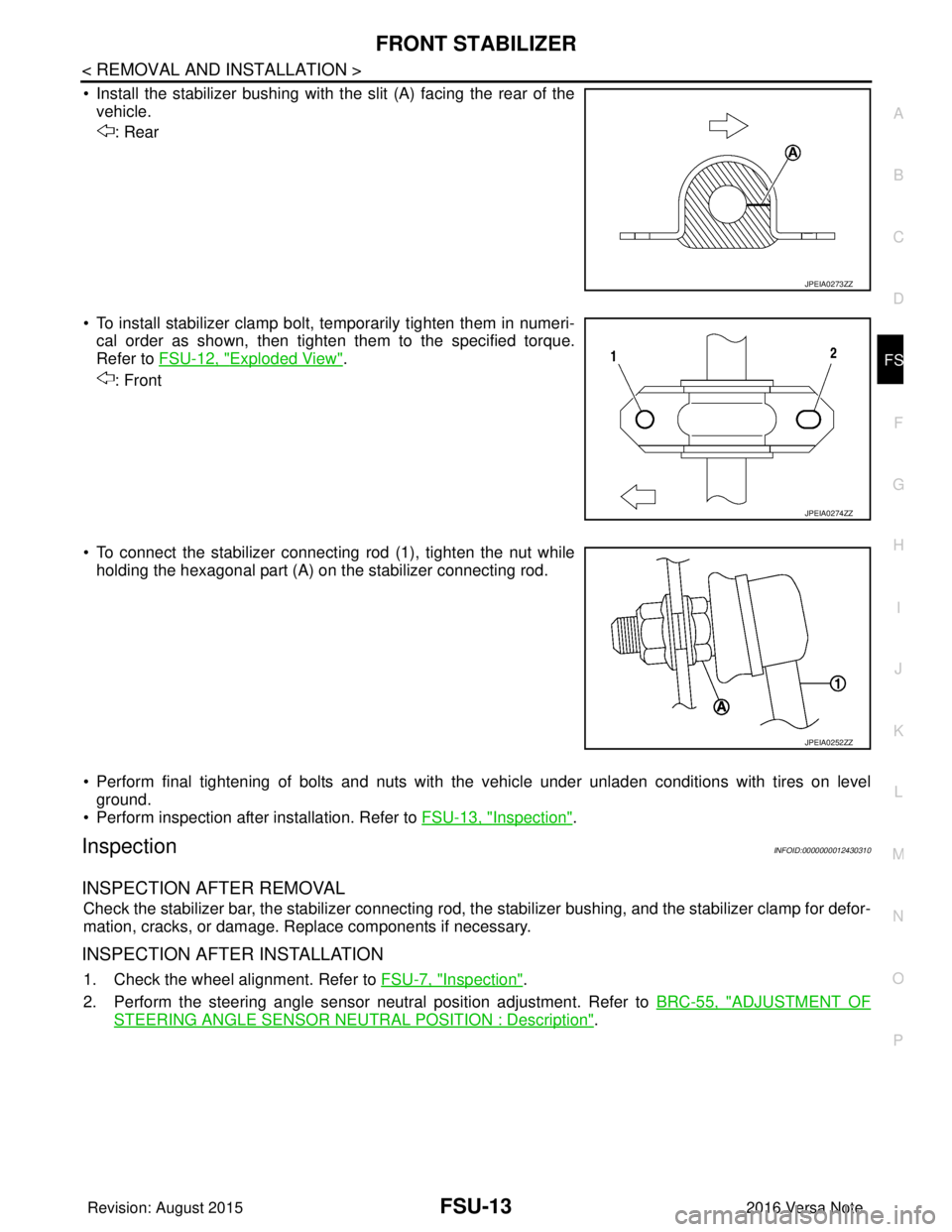
• Install the stabilizer bushing with the slit (A) facing the rear of the vehicle.
: Rear
• To install stabilizer clamp bolt, temporarily tighten them in numeri- cal order as shown, then tighten them to the specified torque.
Refer to FSU-12, "
Exploded View".
: Front
• To connect the stabilizer connecting rod (1), tighten the nut while holding the hexagonal part (A) on the stabilizer connecting rod.
• Perform final tightening of bolts and nuts with the vehicle under unladen conditions with tires on level ground.
• Perform inspection after installation. Refer to FSU-13, "
Inspection".
InspectionINFOID:0000000012430310
INSPECTION AFTER REMOVAL
Check the stabilizer bar, the stabilizer connecting rod, t he stabilizer bushing, and the stabilizer clamp for defor-
mation, cracks, or damage. Replace components if necessary.
INSPECTION AFTER INSTALLATION
1. Check the wheel alignment. Refer to FSU-7, "Inspection".
2. Perform the steering angle sensor neutral position adjustment. Refer to BRC-55, "
ADJUSTMENT OF
STEERING ANGLE SENSOR NEUTRAL POSITION : Description".
JPEIA0273ZZ
JPEIA0274ZZ
JPEIA0252ZZ
Revision: August 2015 2016 Versa Note
cardiagn.com
Page 1859 of 3641
FSU-14
< UNIT REMOVAL AND INSTALLATION >
FRONT SUSPENSION MEMBER
UNIT REMOVAL AND INSTALLATION
FRONT SUSPENSION MEMBER
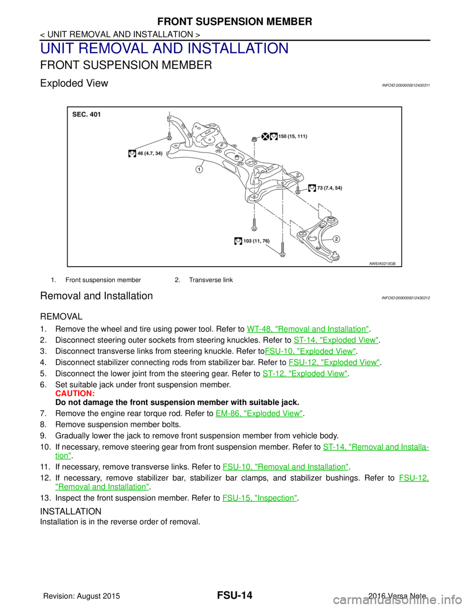
Exploded ViewINFOID:0000000012430311
Removal and InstallationINFOID:0000000012430312
REMOVAL
1. Remove the wheel and tire using power tool. Refer to WT-48, "Removal and Installation".
2. Disconnect steering outer sockets from steering knuckles. Refer to ST-14, "
Exploded View".
3. Disconnect transverse links from steering knuckle. Refer to FSU-10, "
Exploded View".
4. Disconnect stabilizer connecting rods from stabilizer bar. Refer to FSU-12, "
Exploded View".
5. Disconnect the lower joint from the steering gear. Refer to ST-12, "
Exploded View".
6. Set suitable jack under front suspension member. CAUTION:
Do not damage the front suspensi on member with suitable jack.
7. Remove the engine rear torque rod. Refer to EM-86, "
Exploded View".
8. Remove suspension member bolts.
9. Gradually lower the jack to remove front suspension member from vehicle body.
10. If necessary, remove steering gear from front suspension member. Refer to ST-14, "
Removal and Installa-
tion".
11. If necessary, remove transverse links. Refer to FSU-10, "
Removal and Installation".
12. If necessary, remove stabilizer bar, stabilizer bar clamps, and stabilizer bushings. Refer to FSU-12,
"Removal and Installation".
13. Inspect the front suspension member. Refer to FSU-15, "
Inspection".
INSTALLATION
Installation is in the reverse order of removal.
1. Front suspension member2. Transverse link
AWEIA0210GB
Revision: August 2015 2016 Versa Note
cardiagn.com
Page 1889 of 3641

GI-1
GENERAL INFORMATION
C
DE
F
G H
I
J
K L
M B
GI
SECTION GI
N
O P
CONTENTS
GENERAL INFORMATION
HOW TO USE THIS MANU AL ......................3
HOW TO USE THIS MANUAL ....................... .....3
Description .......................................................... ......3
Terms ........................................................................3
Units ..........................................................................3
Contents ....................................................................3
Relation between Illustrations and Descriptions .......4
Components ..............................................................4
HOW TO FOLLOW TROUBLE DIAGNOSES .....6
Description ................................................................6
How to Follow Test Groups in Trouble Diagnosis ......6
Key to Symbols Signifying Measurements or Pro-
cedures ............................................................... ......
7
HOW TO READ WIRING DIAGRAMS ................9
Connector Symbols ............................................. ......9
Sample/Wiring Diagram -Example- .........................10
Connector Information .............................................12
ABBREVIATIONS .......................................... ....14
Abbreviation List .................................................. ....14
TIGHTENING TORQUE OF STANDARD
BOLTS ................................................................
19
Description .......................................................... ....19
Tightening Torque Table (New Standard Includ-
ed) ...........................................................................
19
RECOMMENDED CHEMICAL PRODUCTS
AND SEALANTS ................................................
22
Recommended Chemical Products and Sealants ....22
PRECAUTION ..............................................23
PRECAUTIONS .............................................. ....23
Description .......................................................... ....23
Precaution for Supplemental Restraint System
(SRS) "AIR BAG" and "SEAT BELT PRE-TEN-
SIONER" .................................................................
23
Procedures without Cowl Top Cover .......................23
Cautions in Removing Battery Terminal and AV
Control Unit (Models with AV Control Unit) .............
23
General Precautions ............................................ ....24
Three Way Catalyst .................................................25
Fuel ..........................................................................25
Multiport Fuel Injection System or Engine Control
System .....................................................................
26
Hoses ......................................................................26
Engine Oils ..............................................................27
Air Conditioning .......................................................27
LIFTING POINT .................................................28
Special Service Tool ................................................28
Garage Jack and Safety Stand ................................28
2-Pole Lift ................................................................29
Board-on Lift ............................................................30
TOW TRUCK TOWING .....................................31
Tow Truck Towing ...................................................31
Vehicle Recovery (Freeing a Stuck Vehicle) ...........31
VEHICLE INFORMATION ...........................33
IDENTIFICATION INFORMATION ....................33
Model Variation .................................................... ....33
Identification Number ...............................................34
Identification Plate ...................................................35
Engine Serial Number .............................................36
CVT Number ............................................................36
Manual Transaxle Number ......................................36
Dimensions ..............................................................36
Wheels & Tires ........................................................37
BASIC INSPECTION ...................................38
SERVICE INFORMATION FOR ELECTRICAL
INCIDENT ..........................................................
38
Work Flow ............................................................ ....38
Control Units and Electrical Parts ............................38
How to Check Terminal ...........................................39
Intermittent Incident ............................................. ....42
Circuit Inspection .....................................................44
Revision: August 2015 2016 Versa Note
cardiagn.com
Page 2328 of 3641
ENGINE MAINTENANCEMA-13
< PERIODIC MAINTENANCE >
C
DE
F
G H
I
J
K L
M B
MA
N
O A
ENGINE MAINTENANCE
DRIVE BELT
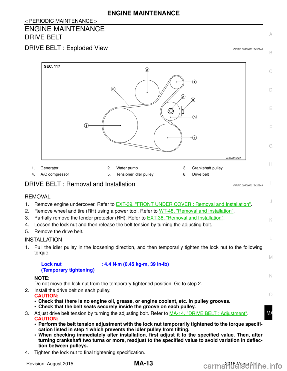
DRIVE BELT : Exploded ViewINFOID:0000000012432248
DRIVE BELT : Removal and InstallationINFOID:0000000012432249
REMOVAL
1. Remove engine undercover. Refer to
EXT-39, "FRONT UNDER COVER : Removal and Installation".
2. Remove wheel and tire (RH) using a power tool. Refer to WT-48, "
Removal and Installation".
3. Partially remove the fender protector (RH). Refer to EXT-38, "
Removal and Installation".
4. Loosen the lock nut and then release the belt tension by turning the adjusting bolt.
5. Remove the drive belt.
INSTALLATION
1. Pull the idler pulley in the loosening direction, and then temporarily tighten the lock nut to the following
torque.
NOTE:
Do not move the lock nut from the temporary tightened position. Go to step 2.
2. Install the drive belt on each pulley. CAUTION:
• Check that there is no engine oil, grease, or engine coolant, etc. in pulley grooves.
• Check that the belt seats securely inside the groove on each pulley.
3. Adjust drive belt tension by turning the adjusting bolt. Refer to MA-14, "
DRIVE BELT : Adjustment".
CAUTION:
• Perform the belt tension adjustment with the lock nut temporarily tightened to the torque specifi-
cation listed in step 1 which preven ts the idler pulley from tilting.
• When checking immediately after in stallation, first adjust it to the specified value. Then, after
turning crankshaft two turns or more, readjust to the specified value to avoid variation in deflec-
tion between pulleys.
4. Tighten the lock nut to final tightening specification.
1. Generator 2. Water pump3. Crankshaft pulley
4. A/C compressor 5. Tensioner idler pulley6. Drive belt
ALBIA1157ZZ
Lock nut
(Temporary tightening): 4.4 N·m (0.45 kg-m, 39 in-lb)
Revision: August 2015
2016 Versa Note
cardiagn.com
Page 3118 of 3641
SR-2
< PRECAUTION >
PRECAUTIONS
PRECAUTION
PRECAUTIONS
Precaution for Supplemental Restraint System (SRS) "AIR BAG" and "SEAT BELT
PRE-TENSIONER"
INFOID:0000000012430560
The Supplemental Restraint System such as “A IR BAG” and “SEAT BELT PRE-TENSIONER”, used along
with a front seat belt, helps to reduce the risk or severity of injury to the driver and front passenger for certain
types of collision. Information necessary to service the system safely is included in the SR and SB section of
this Service Manual.
WARNING:
• To avoid rendering the SRS inopera tive, which could increase the risk of personal injury or death in
the event of a collision which would result in air bag inflation, all maintenance must be performed by
an authorized NISSAN/INFINITI dealer.
• Improper maintenance, including in correct removal and installation of the SRS, can lead to personal
injury caused by unintent ional activation of the system. For re moval of Spiral Cable and Air Bag
Module, see the SR section.
• Do not use electrical test equipmen t on any circuit related to the SRS unless instructed to in this
Service Manual. SRS wiring harn esses can be identified by yellow and/or orange harnesses or har-
ness connectors.
PRECAUTIONS WHEN USING POWER TOOLS (AIR OR ELECTRIC) AND HAMMERS
WARNING:
• When working near the Airbag Diagnosis Sensor Unit or other Airbag System sensors with the Igni-
tion ON or engine running, DO NOT use air or electri c power tools or strike near the sensor(s) with a
hammer. Heavy vibration could activate the sensor( s) and deploy the air bag(s), possibly causing
serious injury.
• When using air or electric power tools or hammers , always switch the Ignition OFF, disconnect the
battery and wait at least three minutes before performing any service.
ServiceINFOID:0000000012430561
• Do not use electrical test equipment to check SRS ci rcuits unless instructed to in this Service Manual.
• Before servicing the SRS, turn ignition switch OFF, disconnect both battery cables and wait at least three
minutes.
For approximately three minutes after the cables are remo ved, it is still possible for the air bag and seat belt
pre-tensioner to deploy. Therefore, do not work on any SRS connectors or wires until at least three minutes
have passed.
• Diagnosis sensor unit must always be installed with their arrow marks “ ⇐” pointing towards the front of the
vehicle for proper operation. Also chec k diagnosis sensor unit for cracks, deformities or rust before installa-
tion and replace as required.
• The spiral cable must be aligned with the neutral position since its rotations are limited. Do not turn steering wheel and column after removal of steering gear.
• Handle air bag module carefully. Always place driver and front passenger air bag modules with the pad side facing upward and seat mounted front side air bag module standing with the stud bolt side facing down.
• Conduct self-diagnosis to check entire SRS for proper function after replacing any components.
• After air bag inflates, the instrument panel assembly should be replaced if damaged.
• Always replace instrument panel pad following front passenger air bag deployment.
Precaution for WorkINFOID:0000000012430562
• When removing or disassembling each component, be careful not to damage or deform it. If a component may be subject to interference, be sure to protect it with a shop cloth.
• When removing (disengaging) components with a screwdriver or similar tool, be sure to wrap the component with a shop cloth or vinyl tape to protect it.
• Protect the removed parts with a shop cloth and prevent them from being dropped.
• Replace a deformed or damaged clip.
• If a part is specified as a non-reusable part, always replace it with a new one.
• Be sure to tighten bolts and nuts securely to the specified torque.
• After installation is complete, be sure to check that each part works properly.
Revision: August 2015 2016 Versa Note
cardiagn.com