Page 2734 of 3641

RSU-6
< PERIODIC MAINTENANCE >
WHEEL ALIGNMENT
WHEEL ALIGNMENT
InspectionINFOID:0000000012431922
DESCRIPTION
Measure the wheel alignment under unladen conditions.
NOTE:
“Unladen conditions” means that fuel, engine coolant, and lubricants are full. Spare tire, jack, hand tools and
mats are in designated positions.
PRELIMINARY
Check the following:
1. Tires for improper air pressure and wear.
2. Road wheels for runout. Refer to WT-44, "
Inspection".
3. Wheel bearing axial end play. Refer to RAX-10, "
Wheel Bearing".
4. Shock absorber operation.
5. Each mounting part of suspension for looseness and deformation.
6. Rear suspension beam for cracks, deformation, and other damage.
7. Vehicle height (posture).
GENERAL INFORMATION AND RECOMMENDATIONS
1. A Four-Wheel Thrust Alignment should be performed. • This type of alignment is recommended for any NISSAN/INFINITI vehicle.
• The four-wheel “thrust” process helps ensure that the vehicle is properly aligned and the steering wheel
is centered.
• The alignment machine itself should be capabl e of accepting any NISSAN/INFINITI vehicle.
• The alignment machine should be checked to ensure that it is level.
2. Make sure the alignment machine is properly calibrated. • Your alignment machine should be regularly calibrated in order to give correct information.
• Check with the manufacturer of your specific al ignment machine for their recommended Service/Cali-
bration Schedule.
THE ALIGNMENT PROCESS
IMPORTANT: Use only the alignment specifications listed in this Service Manual. Refer to RSU-15, "Wheel
Alignment (Unladen*1)".
1. When displaying the alignment settings, many alignment machines use “indicators”: (Green/red, plus or minus, Go/No Go). Do NOT use these indicators.
• The alignment specifications programmed into your alignment machine that operate these indicators may not be correct.
• This may result in an ERROR.
2. Most camera-type alignment machines are equipped with both "Rolling Compensation" method and optional "Jacking Compensation" method to "com pensate" the alignment targets or head units.
"Rolling Compensation" is the preferred method.
• If using the "Rolling Compensation" method, after installing the alignment targets or head units, push or pull on the rear wheel to move the vehicle. Do not push or pull the vehicle body.
• If using the "Jacking Compensation" method, after in stalling the alignment targets or head units, raise
the vehicle and rotate the wheels 1/2 turn both ways.
NOTE:
Do not use the "rolling compensation" if you are using sensor-type alignment equipment.
• Follow all instructions for the alignment machine you're using for more information.
CAMBER INSPECTION
• Measure camber of both right and left wheels with a suitable alignment gauge.
• If it is out of the specificati on value, inspect and replace any damaged or worn rear suspension parts.
Camber : Refer to RSU-15, "
Wheel Alignment
(Unladen*1)".
Revision: August 2015
2016 Versa Note
cardiagn.com
Page 2743 of 3641

SERVICE DATA AND SPECIFICATIONS (SDS)RSU-15
< SERVICE DATA AND SPECIFICATIONS (SDS)
C
DF
G H
I
J
K L
M A
B
RSU
N
O P
SERVICE DATA AND SPECIFICATIONS (SDS)
SERVICE DATA AND SPECIFICATIONS (SDS)
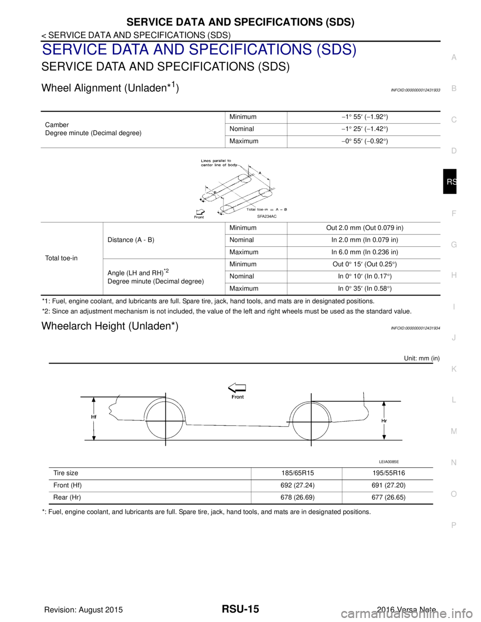
Wheel Alignment (Unladen*1)INFOID:0000000012431933
*1: Fuel, engine coolant, and lubricants are full. Spare tire, jack, hand tools, and mats are in designated positions.
*2: Since an adjustment mechanism is not included, the value of the left and right wheels must be used as the standard value.
Wheelarch Height (Unladen*)INFOID:0000000012431934
Unit: mm (in)
*: Fuel, engine coolant, and lubricants are full. Spare tire, jack, hand tools, and mats are in designated positions. Camber
Degree minute (Decimal degree)
Minimum
−1° 55 ′ ( −1.92 °)
Nominal −1° 25 ′ ( −1.42 °)
Maximum −0° 55 ′ ( −0.92 °)
Total toe-in Distance (A - B)
Minimum
Out 2.0 mm (Out 0.079 in)
Nominal In 2.0 mm (In 0.079 in)
Maximum In 6.0 mm (In 0.236 in)
Angle (LH and RH)
*2
Degree minute (Decimal degree) Minimum Out 0
° 15 ′ (Out 0.25 °)
Nominal In 0° 10 ′ (In 0.17 °)
Maximum In 0° 35 ′ (In 0.58 °)
SFA234AC
Tire size 185/65R15195/55R16
Front (Hf) 692 (27.24)691 (27.20)
Rear (Hr) 678 (26.69)677 (26.65)
LEIA0085E
Revision: August 2015 2016 Versa Note
cardiagn.com
Page 2789 of 3641

WT-46
< PERIODIC MAINTENANCE >
WHEEL AND TIRE
3. Install balance weight in the position shown.CAUTION:
• Do not install the inner bala nce weight before installing
the outer balance weight.
• Before installing the balance weight, be sure to clean the mating surface of the wheel and tire.
• When installing balance weight (1) to wheel and tire, set it into the grooved area (A) on the inner wall of the wheel and tire as
shown so that the balance weight center (B) is aligned with the
balancer machine indication position (angle) (C).
CAUTION:
• Always use Genuine NISSAN adhesive balance weights.
• Balance weights are non-reusable; always replace withnew ones.
• Do not install more than three sheets of balance weights.
4. If calculated balance weight value exceeds 50 g (1.76 oz), install two balance weight sheets in line with each other as shown.
CAUTION:
Do not install one balance weight sheet on top of another.
5. Start balancer machine again.
6. Install balance weight on inner side of wheel and tire in the bal- ancer machine indication position (angle).
CAUTION:
Do not install more than two balance weights.
7. Start balancer machine. Make sure that inner and outer residual imbalance values are 5 g (0.17 oz) each or below.
8. If either residual imbalance value exceeds 5 g (0.17 oz), repeat installation procedures.
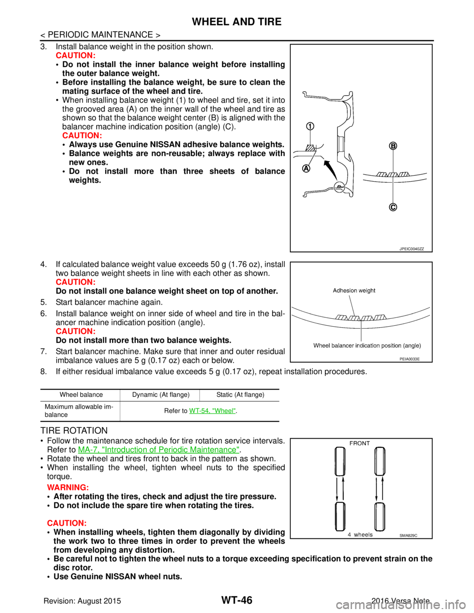
TIRE ROTATION
• Follow the maintenance schedule for tire rotation service intervals.
Refer to MA-7, "
Introduction of Periodic Maintenance".
• Rotate the wheel and tires front to back in the pattern as shown.
• When installing the wheel, tighten wheel nuts to the specified torque.
WARNING:
• After rotating the tires, check and adjust the tire pressure.
• Do not include the spare tire when rotating the tires.
CAUTION:
• When installing wheels, tighten them diagonally by dividing
the work two to three times in order to prevent the wheels
from developing any distortion.
• Be careful not to tighten the wh eel nuts to a torque exceeding speci fication to prevent strain on the
disc rotor.
• Use Genuine NISSAN wheel nuts.
JPEIC0040ZZ
Wheel balance Dynamic (At flange) Static (At flange)
Maximum allowable im-
balance Refer to WT-54, "
Wheel".
PEIA0033E
SMA829C
Revision: August 2015
2016 Versa Note
cardiagn.com
Page 2797 of 3641
WT-54
< SERVICE DATA AND SPECIFICATIONS (SDS)
SERVICE DATA AND SPECIFICATIONS (SDS)
SERVICE DATA AND SPECIFICATIONS (SDS)
SERVICE DATA AND SPECIFICATIONS (SDS)
WheelINFOID:0000000012432473
ALUMINUM WHEEL
STEEL WHEEL
Tire Air PressureINFOID:0000000012432474
Unit: kPa (kg/cm2, psi)
ItemLimit
Runout Axial runout
Less than 0.3 mm (0.012 in)
Radial runout
Allowable imbalance Dynamic (At flange)
Less than 5 g (0.17 oz) (one side)
Static (At flange) Less than 10 g (0.35 oz)
Item Limit
Runout Axial runout
Less than 0.8 mm (0.031 in)
Radial runout Less than 0.5 mm (0.020 in)
Allowable imbalance Dynamic (At flange)
Less than 5 g (0.17 oz) (one side)
Static (At flange) Less than 10 g (0.35 oz)
Tire size Cold tire pressure
Front RearSpare
P185/65R15 86H 230 (2.35, 33)230 (2.35, 33) —
P195/55R16 86V 230 (2.35, 33)230 (2.35, 33) —
T125/70D15 ——420 (4.28, 60)
Revision: August 2015 2016 Versa Note
cardiagn.com