2016 NISSAN NOTE recommended oil
[x] Cancel search: recommended oilPage 1097 of 3641
![NISSAN NOTE 2016 Service Repair Manual EM-96
< UNIT DISASSEMBLY AND ASSEMBLY >[HR16DE]
CYLINDER BLOCK
a. Loosen and remove bolts in several steps in reverse of the
numerical order as shown.
NOTE:
When removing or installing signal plate, u](/manual-img/5/57363/w960_57363-1096.png "NISSAN NOTE 2016 Service Repair Manual EM-96
< UNIT DISASSEMBLY AND ASSEMBLY >[HR16DE]
CYLINDER BLOCK
a. Loosen and remove bolts in several steps in reverse of the
numerical order as shown.
NOTE:
When removing or installing signal plate, u")
EM-96
< UNIT DISASSEMBLY AND ASSEMBLY >[HR16DE]
CYLINDER BLOCK
a. Loosen and remove bolts in several steps in reverse of the
numerical order as shown.
NOTE:
When removing or installing signal plate, use socket (size T40).
b. Remove the main bearing cap from the cylinder block while tapping lightly with a plastic hammer.
10. Remove crankshaft (2). CAUTION:
• Do not damage or deform signal plate (1) mounted on
crankshaft.
• When setting crankshaft on a flat floor surface, use a
block of wood to avoid interf erence between signal plate
and the floor surface.
• Do not remove signal plate unless it is necessary to do
so.
NOTE:
When removing or installing signal plate, use socket (size T40).
11. Pull rear oil seal out from rear end of crankshaft.
12. Remove main bearing (upper/lower) and thrust bear ings from cylinder block and main bearing caps.
CAUTION:
Identify original installation positions, and store the bearings without mixing them up.
13. Remove oil jets. CAUTION:
Insert the dowel pin of oil jet into the cylinde r block dowel pin hole to loosen the bolt.
ASSEMBLY
CAUTION:
Do not reuse O-rings.
1. Fully air-blow engine coolant and engine oil passages in cylinder block, cylinder bore and crankcase to
remove any foreign material.
WARNING:
Use goggles to protect your eyes.
2. Install cylinder block plugs. • Apply liquid gasket to the thread of water drain plug (3).
Use Genuine Silicone RTV Seal ant, or equivalent. Refer to
GI-22, "
Recommended Chemical Products and Sealants".
CAUTION:
Do not reuse O-ring.
• Tighten each plug as specified below.
: Engine front
JPBIA4203ZZ
JPBIA4531ZZ
(2) : O-ring : Engine front
AWBIA1607ZZ
Part WasherTightening torque
(1) Yes54.0 N·m (5.5 kg-m, 40 ft-lb)
(3) No9.8 N·m (1.0 kg-m, 87 in-lb)
Revision: August 2015 2016 Versa Note
cardiagn.com
Page 1163 of 3641
![NISSAN NOTE 2016 Service Repair Manual EC-36
< SYSTEM DESCRIPTION >[HR16DE]
SYSTEM
*1: M/T models
*2: CVT models
*3: ECM determines the start signal status
by the signals of engine speed and battery voltage.
*4: This signal is sent to the](/manual-img/5/57363/w960_57363-1162.png "NISSAN NOTE 2016 Service Repair Manual EC-36
< SYSTEM DESCRIPTION >[HR16DE]
SYSTEM
*1: M/T models
*2: CVT models
*3: ECM determines the start signal status
by the signals of engine speed and battery voltage.
*4: This signal is sent to the")
EC-36
< SYSTEM DESCRIPTION >[HR16DE]
SYSTEM
*1: M/T models
*2: CVT models
*3: ECM determines the start signal status
by the signals of engine speed and battery voltage.
*4: This signal is sent to the ECM through CAN communication line.
SYSTEM DESCRIPTION
Firing order: 1 - 3 - 4 - 2
The ignition timing is controlled by the ECM to maintain the best air-fuel ratio for every running condition of the
engine. The ignition timing data is stored in the ECM.
The ECM receives information such as the injection pulse width and camshaft position sensor signal. Comput-
ing this information, ignition signals are transmitted to the power transistor.
During the following conditions, the ignition timing is re vised by the ECM according to the other data stored in
the ECM.
• At starting
• During warm-up
• At idle
• At low battery voltage
• During acceleration
The knock sensor retard system is designed only for emergencies. The basic ignition timing is programmed
within the anti-knocking zone, if recommended fuel is used under dry conditions. The retard system does not
operate under normal driving conditions. If engine knocking occurs, the \
knock sensor monitors the condition.
The signal is transmitted to the ECM. The ECM retards the ignition timing to eliminate the knocking condition.
AIR CONDITIONING CUT CONTROL
SensorInput signal to ECM ECM function Actuator
Crankshaft position sensor (POS) Engine speed
*3
Piston position
Ignition timing control Ignition coil (with power transistor)
Camshaft position sensor (PHASE)
Mass air flow sensor
Amount of intake air
Engine coolant temperature sensor Engine coolant temperature
Throttle position sensor Throttle position
Accelerator pedal position sensor Accelerator pedal position
Park/neutral position (PNP) switch
*1
PNP signal
Transmission range switch*2
Battery Battery voltage*3
Knock sensorEngine knocking
Combination meter Vehicle speed
*4
Revision: August 2015 2016 Versa Note
cardiagn.com
Page 1633 of 3641
![NISSAN NOTE 2016 Service Repair Manual PRECAUTIONSLU-3
< PRECAUTION > [HR16DE]
C
D
E
F
G H
I
J
K L
M A
LU
NP
O
3. Attach liquid gasket tube to the suitable tool.
Use Genuine Silicone RTV Sealant, or equivalent. Refer to
GI-22, "
Recommend](/manual-img/5/57363/w960_57363-1632.png "NISSAN NOTE 2016 Service Repair Manual PRECAUTIONSLU-3
< PRECAUTION > [HR16DE]
C
D
E
F
G H
I
J
K L
M A
LU
NP
O
3. Attach liquid gasket tube to the suitable tool.
Use Genuine Silicone RTV Sealant, or equivalent. Refer to
GI-22, \"
Recommend")
PRECAUTIONSLU-3
< PRECAUTION > [HR16DE]
C
D
E
F
G H
I
J
K L
M A
LU
NP
O
3. Attach liquid gasket tube to the suitable tool.
Use Genuine Silicone RTV Sealant, or equivalent. Refer to
GI-22, "
Recommended Chemical Products and Sealants".
4. Apply liquid gasket without gaps to the specified location accord- ing to the specified dimensions.
• If there is a groove for liquid gasket application, apply liquidgasket to the groove.
• As for bolt holes (B), normally apply liquid gasket inside the holes. Occasionally, it should be applied outside the holes.
Check to read the text of this manual.
• Within five minutes of liquid gasket application, install the mat- ing component.
• If liquid gasket protrudes, wipe it off immediately.
• Do not retighten mounting bolts or nuts after the installation.
• After 30 minutes or more have passed from the installation, fill engine oil and engine coolant.
CAUTION:
If there are specific instructions in the procedures contained in this manual concerning liquid gasket
application, observe them.
EMA0622D
(A) : Groove
: Inside
JPBIA0010ZZ
Revision: August 2015 2016 Versa Note
cardiagn.com
Page 1638 of 3641
![NISSAN NOTE 2016 Service Repair Manual LU-8
< PERIODIC MAINTENANCE >[HR16DE]
ENGINE OIL
2. Disconnect harness connector at
oil pressure sensor. Remove
oil pressure sensor using suitable tool and install suitable tools
(A/B).
CAUTION:
Do n](/manual-img/5/57363/w960_57363-1637.png "NISSAN NOTE 2016 Service Repair Manual LU-8
< PERIODIC MAINTENANCE >[HR16DE]
ENGINE OIL
2. Disconnect harness connector at
oil pressure sensor. Remove
oil pressure sensor using suitable tool and install suitable tools
(A/B).
CAUTION:
Do n")
LU-8
< PERIODIC MAINTENANCE >[HR16DE]
ENGINE OIL
2. Disconnect harness connector at
oil pressure sensor. Remove
oil pressure sensor using suitable tool and install suitable tools
(A/B).
CAUTION:
Do not drop or shock oil pressure sensor.
3. Start engine and warm it up to normal operating temperature.
4. Check engine oil pressure with engine running under no-load. NOTE:
• When engine oil temperature is low, engine oil pressure becomes high.
• If difference is extreme, check oil passage and oil pump for engine oil leaks.
5. After the inspections, install oil pressure sensor as follows:
a. Remove old liquid gasket adhering to oil pressure sensor and engine.
b. Apply liquid gasket and tighten oil pressure sensor to specification. Use Genuine Liquid Gasket or equivalent. Refer to GI-22, "
Recommended Chemical Products and
Sealants".
6. Check engine oil level.
7. After warming up engine, check that ther e is no engine oil leaks with the running engine.
DrainingINFOID:0000000012432201
WARNING:
• Be careful not to get burned, as engine oil may be hot.
• Prolonged and repeated contact with used engine oil may cause ski n cancer. Try to avoid direct skin
contact with used engine oil. If skin contact is made, wash thoroughly with soap or hand cleaner as
soon as possible.
1. Warm up the engine, park the vehicle on a level surface and check for engine oil leaks. Refer to LU-7,
"Inspection".
2. Stop the engine and wait for 10 minutes.
3. Loosen oil filler cap.
4. Remove drain plug and then drain engine oil.
RefillingINFOID:0000000012432202
1. Install drain plug with new copper sealing washer. Refer to EM-34, "Exploded View".
CAUTION:
• Be sure to clean drain plug.
• Do not reuse copper sealing washer.
2. Refill with new engine oil.
CAUTION:
• The refill capacity depends on the engine oi l temperature and drain time. Use these specifica-
tions for reference only.
• Always use oil level gauge to determine the pr oper amount of engine oil in the engine.
JPBIA0074ZZ
Engine oil pressure : Refer to LU-15, "Engine Oil Pressure".
Tightening torque : Refer to EM-93, "
Exploded View".
Engine oil capacity and viscosity : Refer to MA-11, "
Fluids and Lubricants".
Revision: August 2015 2016 Versa Note
cardiagn.com
Page 1889 of 3641

GI-1
GENERAL INFORMATION
C
DE
F
G H
I
J
K L
M B
GI
SECTION GI
N
O P
CONTENTS
GENERAL INFORMATION
HOW TO USE THIS MANU AL ......................3
HOW TO USE THIS MANUAL ....................... .....3
Description .......................................................... ......3
Terms ........................................................................3
Units ..........................................................................3
Contents ....................................................................3
Relation between Illustrations and Descriptions .......4
Components ..............................................................4
HOW TO FOLLOW TROUBLE DIAGNOSES .....6
Description ................................................................6
How to Follow Test Groups in Trouble Diagnosis ......6
Key to Symbols Signifying Measurements or Pro-
cedures ............................................................... ......
7
HOW TO READ WIRING DIAGRAMS ................9
Connector Symbols ............................................. ......9
Sample/Wiring Diagram -Example- .........................10
Connector Information .............................................12
ABBREVIATIONS .......................................... ....14
Abbreviation List .................................................. ....14
TIGHTENING TORQUE OF STANDARD
BOLTS ................................................................
19
Description .......................................................... ....19
Tightening Torque Table (New Standard Includ-
ed) ...........................................................................
19
RECOMMENDED CHEMICAL PRODUCTS
AND SEALANTS ................................................
22
Recommended Chemical Products and Sealants ....22
PRECAUTION ..............................................23
PRECAUTIONS .............................................. ....23
Description .......................................................... ....23
Precaution for Supplemental Restraint System
(SRS) "AIR BAG" and "SEAT BELT PRE-TEN-
SIONER" .................................................................
23
Procedures without Cowl Top Cover .......................23
Cautions in Removing Battery Terminal and AV
Control Unit (Models with AV Control Unit) .............
23
General Precautions ............................................ ....24
Three Way Catalyst .................................................25
Fuel ..........................................................................25
Multiport Fuel Injection System or Engine Control
System .....................................................................
26
Hoses ......................................................................26
Engine Oils ..............................................................27
Air Conditioning .......................................................27
LIFTING POINT .................................................28
Special Service Tool ................................................28
Garage Jack and Safety Stand ................................28
2-Pole Lift ................................................................29
Board-on Lift ............................................................30
TOW TRUCK TOWING .....................................31
Tow Truck Towing ...................................................31
Vehicle Recovery (Freeing a Stuck Vehicle) ...........31
VEHICLE INFORMATION ...........................33
IDENTIFICATION INFORMATION ....................33
Model Variation .................................................... ....33
Identification Number ...............................................34
Identification Plate ...................................................35
Engine Serial Number .............................................36
CVT Number ............................................................36
Manual Transaxle Number ......................................36
Dimensions ..............................................................36
Wheels & Tires ........................................................37
BASIC INSPECTION ...................................38
SERVICE INFORMATION FOR ELECTRICAL
INCIDENT ..........................................................
38
Work Flow ............................................................ ....38
Control Units and Electrical Parts ............................38
How to Check Terminal ...........................................39
Intermittent Incident ............................................. ....42
Circuit Inspection .....................................................44
Revision: August 2015 2016 Versa Note
cardiagn.com
Page 1913 of 3641
PRECAUTIONSGI-25
< PRECAUTION >
C
DE
F
G H
I
J
K L
M B
GI
N
O P
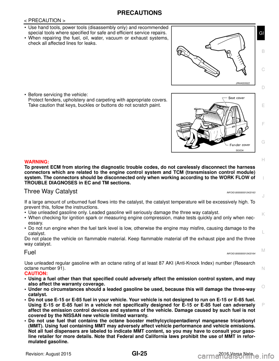
• Use hand tools, power tools (disassembly only) and recommended special tools where specified for safe and efficient service repairs.
• When repairing the fuel, oil, water, vacuum or exhaust systems,
check all affected lines for leaks.
• Before servicing the vehicle: Protect fenders, upholstery and carpeting with appropriate covers.
Take caution that keys, buckles or buttons do not scratch paint.
WARNING:
To prevent ECM from storing the diagnostic trou ble codes, do not carelessly disconnect the harness
connectors which are related to the engine cont rol system and TCM (transmission control module)
system. The connectors should be disconnected only when working according to the WORK FLOW of
TROUBLE DIAGNOSES in EC and TM sections.
Three Way CatalystINFOID:0000000012433163
If a large amount of unburned fuel flows into the catalyst, the catalyst temperature will be excessively high. To
prevent this, follow the instructions.
• Use unleaded gasoline only. Leaded gasoline will seriously damage the three way catalyst.
• When checking for ignition spark or measuring engine compression, make tests quickly and only when nec-
essary.
• Do not run engine when the fuel tank level is low, otherwise the engine may misfire, causing damage to the
catalyst.
Do not place the vehicle on flammable material. Keep flammable material off the exhaust pipe and the three
way catalyst.
FuelINFOID:0000000012433164
Use unleaded regular gasoline with an octane rating of at least 87 AKI (Anti-Knock Index) number (Research
octane number 91).
CAUTION:
• Using a fuel other than that specified could adversely affect th e emission control system, and may
also affect the warranty coverage.
• Under no circumstances should a leaded gasoline be used, because this will damage the three-way
catalyst.
• Do not use E-15 or E-85 fuel in your vehicle. Your vehicle is not designed to run on E-15 or E-85 fuel. Using E-15 or E-85 fuel in a vehicle not specifically designed for E-15 or E-85 fuel can adversely
affect the emission control devices and systems of the vehicle. Damage caused by such fuel is not
covered by the NISSAN new vehicle limited warranty.
• Do not use fuel that contains the octane boo ster methylcyclopentadienyl manganese tricarbonyl
(MMT). Using fuel containing MM T may adversely affect vehicle pe rformance and vehicle emissions.
Not all fuel dispensers are labeled to indicate MMT content, so you may have to consult your gaso-
line retailer for more details. Note that Federal and California laws prohibit the use of MMT in refor-
mulated gasoline.
JPAIA0335ZZ
SGI234
Revision: August 2015 2016 Versa Note
cardiagn.com
Page 1974 of 3641
![NISSAN NOTE 2016 Service Repair Manual HAC-6
< PRECAUTION >[MANUAL AIR CONDITIONING]
PRECAUTIONS
• The fluorescent leak detection dye is not a replacem
ent for an electronic leak detector. The fluores-
cent leak detection dye should be u](/manual-img/5/57363/w960_57363-1973.png "NISSAN NOTE 2016 Service Repair Manual HAC-6
< PRECAUTION >[MANUAL AIR CONDITIONING]
PRECAUTIONS
• The fluorescent leak detection dye is not a replacem
ent for an electronic leak detector. The fluores-
cent leak detection dye should be u")
HAC-6
< PRECAUTION >[MANUAL AIR CONDITIONING]
PRECAUTIONS
• The fluorescent leak detection dye is not a replacem
ent for an electronic leak detector. The fluores-
cent leak detection dye should be u sed in conjunction with an electronic leak detector to pin-point
refrigerant leaks.
• Read and follow all manufacture’s operating inst ructions and precautions prior to performing the
work for the purpose of safet y and customer’s satisfaction.
• A compressor shaft seal should not necessarily be repaired becau se of dye seepage. The compres-
sor shaft seal should only be repaired after conf irming the leak with an electronic leak detector.
• Always remove any remaining dye from the leak area after repairs are completed to avoid a misdiag-
nosis during a future service.
• Do not allow dye to come into contact with painted body panels or interior components. Clean imme- diately with the approved dye cl eaner if dye is spilled. Fluorescent dye left on a surface for an
extended period of time cannot be removed.
• Do not spray the fluorescent dye cleaning agent on hot surfaces (engine exhaust manifold, etc.).
• Do not use more than one refrigerant dye bottle [1/4 ounce (7.4 cc)] per A/C system.
• Leak detection dyes for HFC-134a (R-134a) and CFC-12 (R-12) A/C systems are different. Do not use
HFC-134a (R-134a) leak detection dye in CFC-12 (R-12) A/C system, or CFC-12 (R-12) leak detection
dye in HFC-134a (R-134a) A/C system, or A/C system damage may result.
• The fluorescent properties of the dye remains fo r three or more years unless a compressor malfunc-
tion occurs.
NOTE: Identification
• Vehicles with factory installed fluorescent dye have a green label.
• Vehicles without factory installed fluorescent dye have a blue label.
Service EquipmentINFOID:0000000012430713
RECOVERY/RECYCLING RECHARGING EQUIPMENT
Be certain to follow the manufacturer’s instructions for machine operation and machine maintenance. Do not
introduce any refrigerant other than that specified into the machine.
ELECTRICAL LEAK DETECTOR
Be certain to follow the manufacturer’s instruct ions for tester operation and tester maintenance.
VACUUM PUMP
The oil contained inside the vacuum pump is not compatible with the
specified oil for HFC-134a (R-134a) A/C systems. The vent side of
the vacuum pump is exposed to atmospheric pressure. Vacuum
pump oil may migrate out of the pump into the service hose. This is
possible when the pump is switc hed OFF after evacuation (vacuum-
ing) and hose is connected to it.
To prevent this migration, use a manual valve placed near the hose-
to-pump connection, as per the following.
• Vacuum pumps usually have a manual isolator valve as part of the pump. Close this valve to isolat e the service hose from the pump.
• Use a hose equipped with a manual shut-off valve near the pump
end for pumps without an isolator. Close the valve to isolate the
hose from the pump.
• Disconnect the hose from the pump if the hose has an automatic
shut-off valve. As long as the hose is connected, the valve is open
and lubricating oil may migrate.
Some one-way valves open when vacuum is applied and close
under no vacuum condition. Such valves may restrict the pump’s
ability to pull a deep vacuum and are not recommended.
MANIFOLD GAUGE SET
RHA270DA
Revision: August 2015 2016 Versa Note
cardiagn.com
Page 2030 of 3641
PRECAUTIONSHA-5
< PRECAUTION >
C
DE
F
G H
J
K L
M A
B
HA
N
O P
• Expansion valve to evaporator
• Refrigerant pressure sensor to liquid tank
WARNING:
Check that all refrigerant is discharged into the recycling equipment and the pressure in the system is
less than atmospheric pressure. Then gradually loo sen the discharge side hose fitting and remove it.
CAUTION:
Observe the following when replacing or cleaning refrigerant cycle components.
• Store it in the same way as it is when mounted on the vehicle when the compressor is removed. Fail- ure to do so will cause oil to enter the low-pressure chamber.
• Always use a torque wrench and a back-up wrench when connecting tubes.
• Immediately plug all openings to prevent entry of dust and moisture after disconnecting tubes.
• Connect the pipes at the final stag e of the operation when installing an air conditioner in the vehicle.
Do not remove the seal caps of pipes and other comp onents until just before required for connec-
tion.
• Allow components stored in cool areas to warm to working area temperature before removing seal
caps. This prevents condensation from forming inside A/C components.
• Remove moisture thoroughly from the refriger ation system before charging the refrigerant.
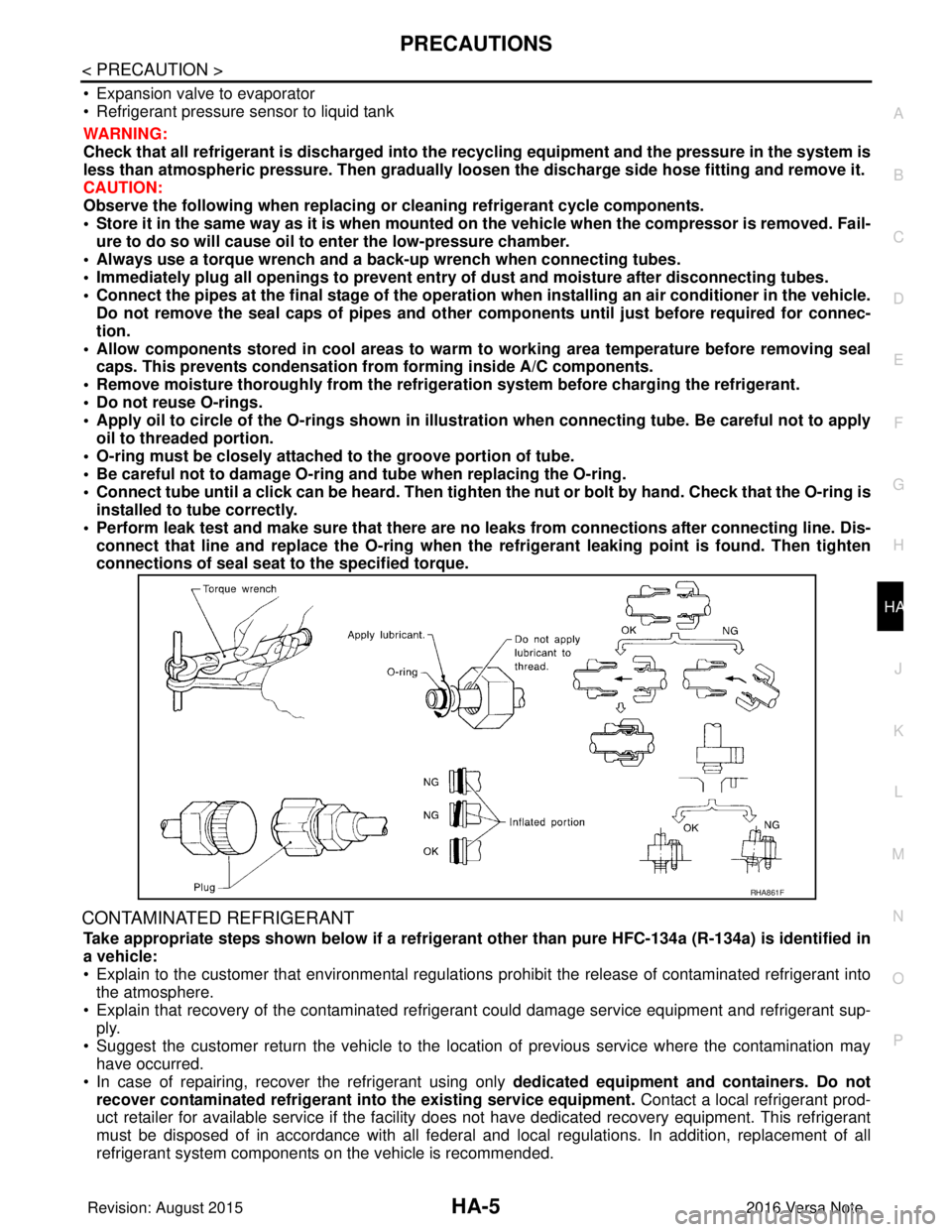
• Do not reuse O-rings.
• Apply oil to circle of the O-rings shown in illust ration when connecting tube. Be careful not to apply
oil to threaded portion.
• O-ring must be closely attached to the groove portion of tube.
• Be careful not to damage O-ring and tube when replacing the O-ring.
• Connect tube until a click can be heard. Then tighten the nut or bolt by hand. Check that the O-ring is
installed to tube correctly.
• Perform leak test and make sure that there are no leaks from connections after connecting line. Dis-
connect that line and replace the O-ring when the refrigerant leaking point is found. Then tighten
connections of seal seat to the specified torque.
CONTAMINATED REFRIGERANT
Take appropriate steps shown below if a refrigerant other than pure HFC-134a (R-134a) is identified in
a vehicle:
• Explain to the customer that environmental regulations prohibit the release of contaminated refrigerant into
the atmosphere.
• Explain that recovery of the contaminated refri gerant could damage service equipment and refrigerant sup-
ply.
• Suggest the customer return the vehicle to the locati on of previous service where the contamination may
have occurred.
• In case of repairing, recover the refrigerant using only dedicated equipment and containers. Do not
recover contaminated refrigerant into the existing service equipment. Contact a local refrigerant prod-
uct retailer for available service if the facility does not have dedicated recovery equipment. This refrigerant
must be disposed of in accordance with all federal and local regulations. In addition, replacement of all
refrigerant system components on the vehicle is recommended.
RHA861F
Revision: August 2015 2016 Versa Note
cardiagn.com