2016 NISSAN NOTE wiring
[x] Cancel search: wiringPage 673 of 3641

DEF-22
< DTC/CIRCUIT DIAGNOSIS >
REAR WINDOW DEFOGGER RELAY
REAR WINDOW DEFOGGER RELAY
DescriptionINFOID:0000000012431767
Power is supplied to the rear window defogger with BCM control.
Component Function CheckINFOID:0000000012431768
1.CHECK FUNCTION
1. Turn ignition switch ON.
2. Check that an operation noise of rear window defogger relay can be heard when turning the rear window defogger switch ON.
Is the inspection result normal?
YES >> Rear window defogger relay function is OK.
NO >> Refer to DEF-22, "
Diagnosis Procedure"
Diagnosis ProcedureINFOID:0000000012431769
Regarding Wiring Diagram information, refer to DEF-12, "Wiring Diagram".
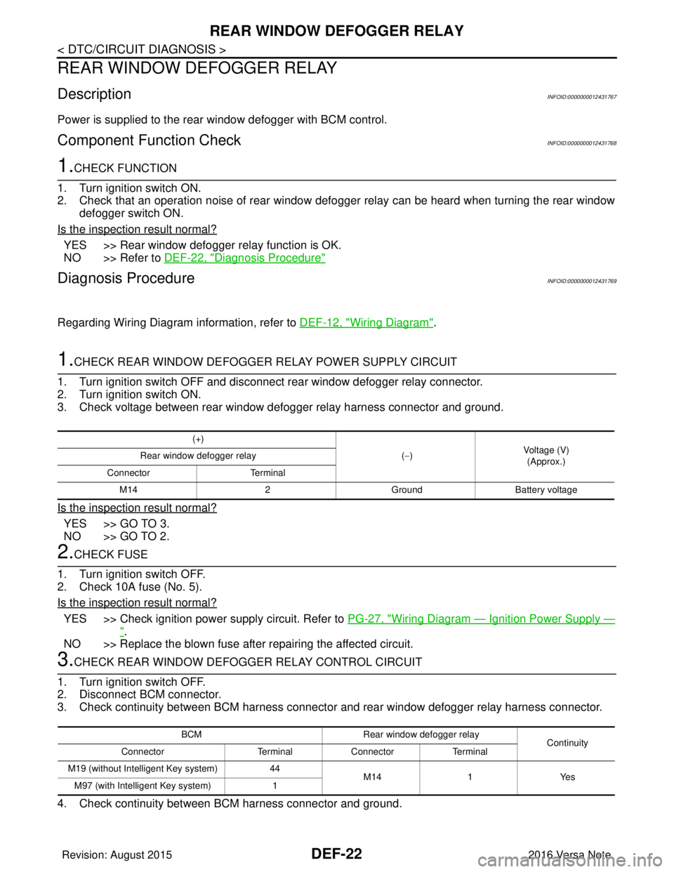
1.CHECK REAR WINDOW DEFOGGER RELAY POWER SUPPLY CIRCUIT
1. Turn ignition switch OFF and disconnect rear window defogger relay connector.
2. Turn ignition switch ON.
3. Check voltage between rear window defogger relay harness connector and ground.
Is the inspection result normal?
YES >> GO TO 3.
NO >> GO TO 2.
2.CHECK FUSE
1. Turn ignition switch OFF.
2. Check 10A fuse (No. 5).
Is the inspection result normal?
YES >> Check ignition power supply circuit. Refer to PG-27, "Wiring Diagram — Ignition Power Supply —
".
NO >> Replace the blown fuse after repairing the affected circuit.
3.CHECK REAR WINDOW DEFOGGER RELAY CONTROL CIRCUIT
1. Turn ignition switch OFF.
2. Disconnect BCM connector.
3. Check continuity between BCM harness connector and rear window defogger relay harness connector.
4. Check continuity between BCM harness connector and ground.
(+)
(−) Voltage (V)
(Approx.)
Rear window defogger relay
Connector Terminal
M14 2GroundBattery voltage
BCM Rear window defogger relay
Continuity
Connector TerminalConnector Terminal
M19 (without Intelligent Key system) 44
M14 1Yes
M97 (with Intelligent Key system) 1
Revision: August 2015 2016 Versa Note
cardiagn.com
Page 675 of 3641

DEF-24
< DTC/CIRCUIT DIAGNOSIS >
REAR WINDOW DEFOGGER POWER SUPPLY AND GROUND CIRCUIT
REAR WINDOW DEFOGGER POWER SUPPLY AND GROUND CIRCUIT
DescriptionINFOID:0000000012431771
Heats the heating wire with the power supply from the rear window defogger relay to prevent the rear window
from fogging up.
Component Function CheckINFOID:0000000012431772
1. CHECK REAR WINDOW DEFOGGER
Check that the heating wire of rear window defogger is heated when turning the rear window defogger switch
ON.
Is the inspection result normal?
YES >> Rear window defogger is OK.
NO >> Refer to DEF-24, "
Diagnosis Procedure".
Diagnosis ProcedureINFOID:0000000012431773
Regarding Wiring Diagram information, refer to DEF-12, "Wiring Diagram".
1. CHECK FUSES
Check if any of the following fuses in fuse block (J/B) are blown.
Is the inspection result normal?
YES >> GO TO 2.
NO >> Replace the blown fuse after repairing the affected circuit.
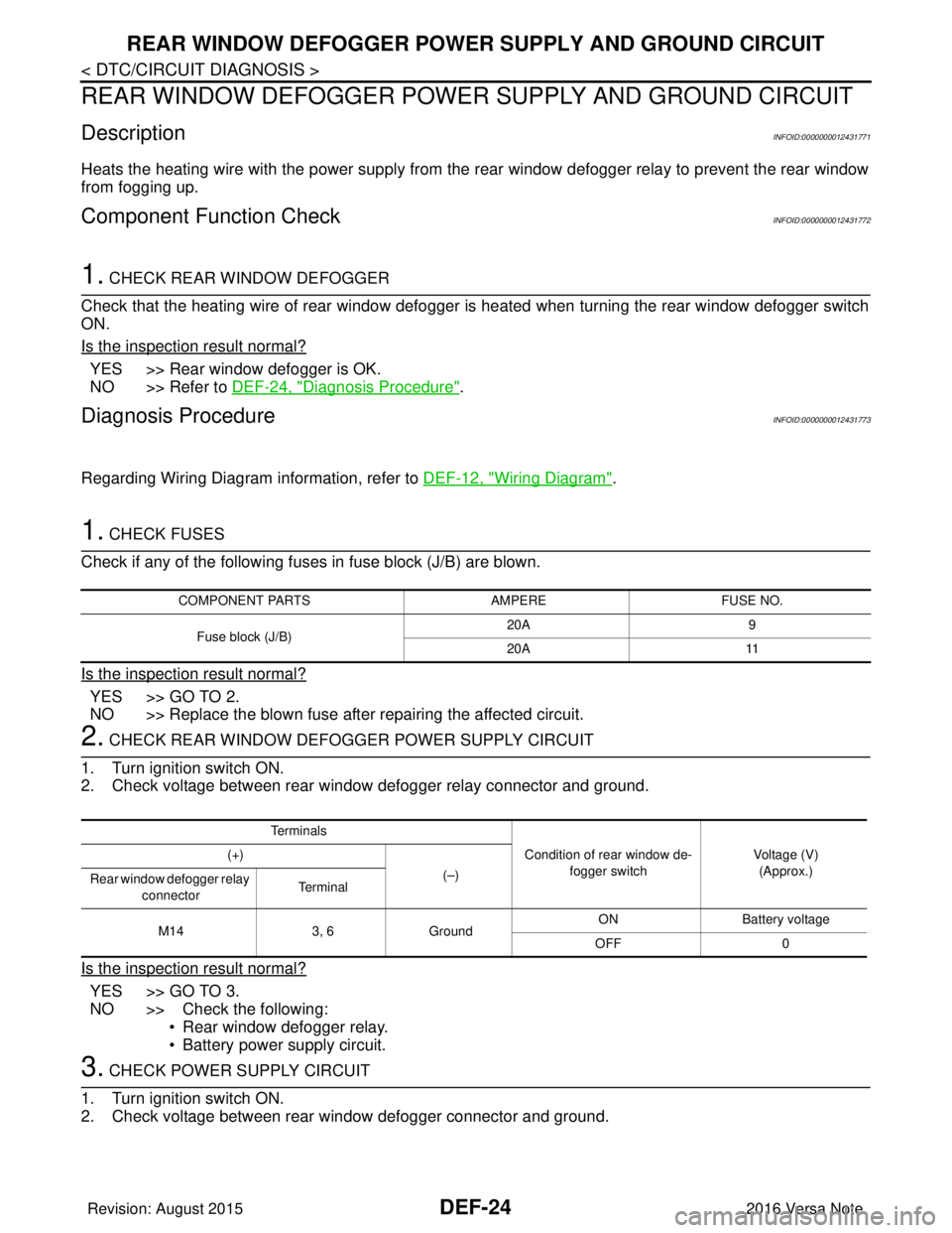
2. CHECK REAR WINDOW DEFOGGER POWER SUPPLY CIRCUIT
1. Turn ignition switch ON.
2. Check voltage between rear window defogger relay connector and ground.
Is the inspection result normal?
YES >> GO TO 3.
NO >> Check the following: • Rear window defogger relay.
• Battery power supply circuit.
3. CHECK POWER SUPPLY CIRCUIT
1. Turn ignition switch ON.
2. Check voltage between rear window defogger connector and ground.
COMPONENT PARTS AMPEREFUSE NO.
Fuse block (J/B) 20A
9
20A 11
Te r m i n a l s
Condition of rear window de-fogger switch Voltage (V)
(Approx.)
(+)
(–)
Rear window defogger relay
connector Te r m i n a l
M14 3, 6Ground ON Battery
voltage
OFF 0
Revision: August 2015 2016 Versa Note
cardiagn.com
Page 677 of 3641

DEF-26
< DTC/CIRCUIT DIAGNOSIS >
DRIVER SIDE DOOR MIRROR DEFOGGER
DRIVER SIDE DOOR MIRROR DEFOGGER
DescriptionINFOID:0000000012431775
Heats the heating wire with the power supply from the rear window defogger relay to prevent the door mirror
from fogging up.
Component Function CheckINFOID:0000000012431776
1. CHECK DOOR MIRROR DEFOGGER LH
Check that heating wire of door mirror defogger LH is heated when turning the rear window defogger switch
ON.
Is the inspection result normal?
YES >> Door mirror defogger is OK.
NO >> Refer to DEF-26, "
Diagnosis Procedure".
Diagnosis ProcedureINFOID:0000000012431777
Regarding Wiring Diagram information, refer to DEF-12, "Wiring Diagram".
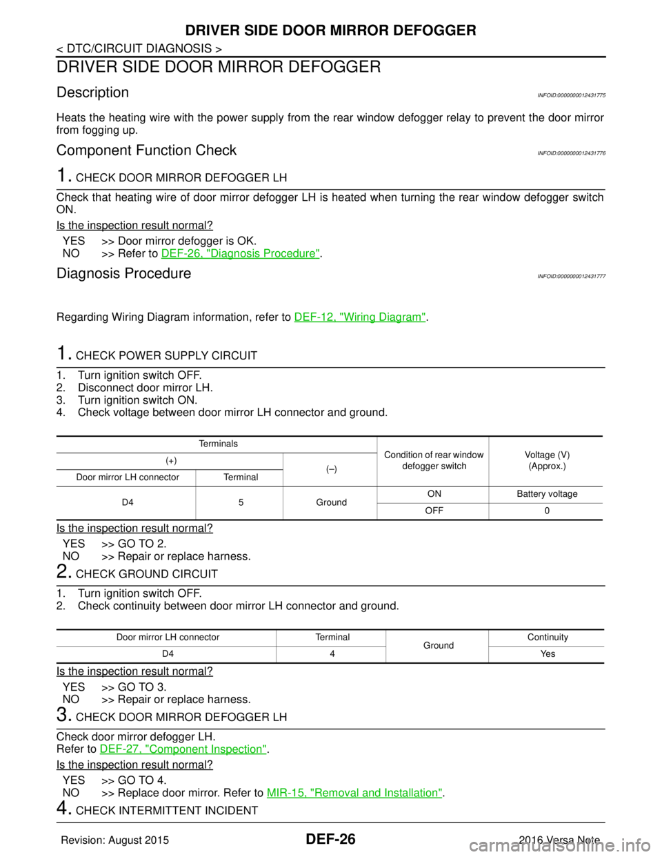
1. CHECK POWER SUPPLY CIRCUIT
1. Turn ignition switch OFF.
2. Disconnect door mirror LH.
3. Turn ignition switch ON.
4. Check voltage between door mirror LH connector and ground.
Is the inspection result normal?
YES >> GO TO 2.
NO >> Repair or replace harness.
2. CHECK GROUND CIRCUIT
1. Turn ignition switch OFF.
2. Check continuity between door mirror LH connector and ground.
Is the inspection result normal?
YES >> GO TO 3.
NO >> Repair or replace harness.
3. CHECK DOOR MIRROR DEFOGGER LH
Check door mirror defogger LH.
Refer to DEF-27, "
Component Inspection".
Is the inspection result normal?
YES >> GO TO 4.
NO >> Replace door mirror. Refer to MIR-15, "
Removal and Installation".
4. CHECK INTERMITTENT INCIDENT
Te r m i n a l s
Condition of rear window
defogger switch Voltage (V)
(Approx.)
(+)
(–)
Door mirror LH connector Terminal
D4 5Ground ON
Battery voltage
OFF 0
Door mirror LH connector Terminal
GroundContinuity
D4 4 Yes
Revision: August 2015 2016 Versa Note
cardiagn.com
Page 679 of 3641

DEF-28
< DTC/CIRCUIT DIAGNOSIS >
PASSENGER SIDE DOOR MIRROR DEFOGGER
PASSENGER SIDE DOOR MIRROR DEFOGGER
DescriptionINFOID:0000000012431779
Heats the heating wire with the power supply from the rear window defogger relay to prevent the door mirror
from fogging up.
Component Function CheckINFOID:0000000012431780
1.CHECK DOOR MIRROR DEFOGGER RH
Check that the heating wire of door mirror defogger RH is heated when turning the rear window defogger
switch ON.
Is the inspection result normal?
YES >> Door mirror defogger RH is OK.
NO >> Refer to DEF-28, "
Diagnosis Procedure".
Diagnosis ProcedureINFOID:0000000012431781
Regarding Wiring Diagram information, refer to DEF-12, "Wiring Diagram".
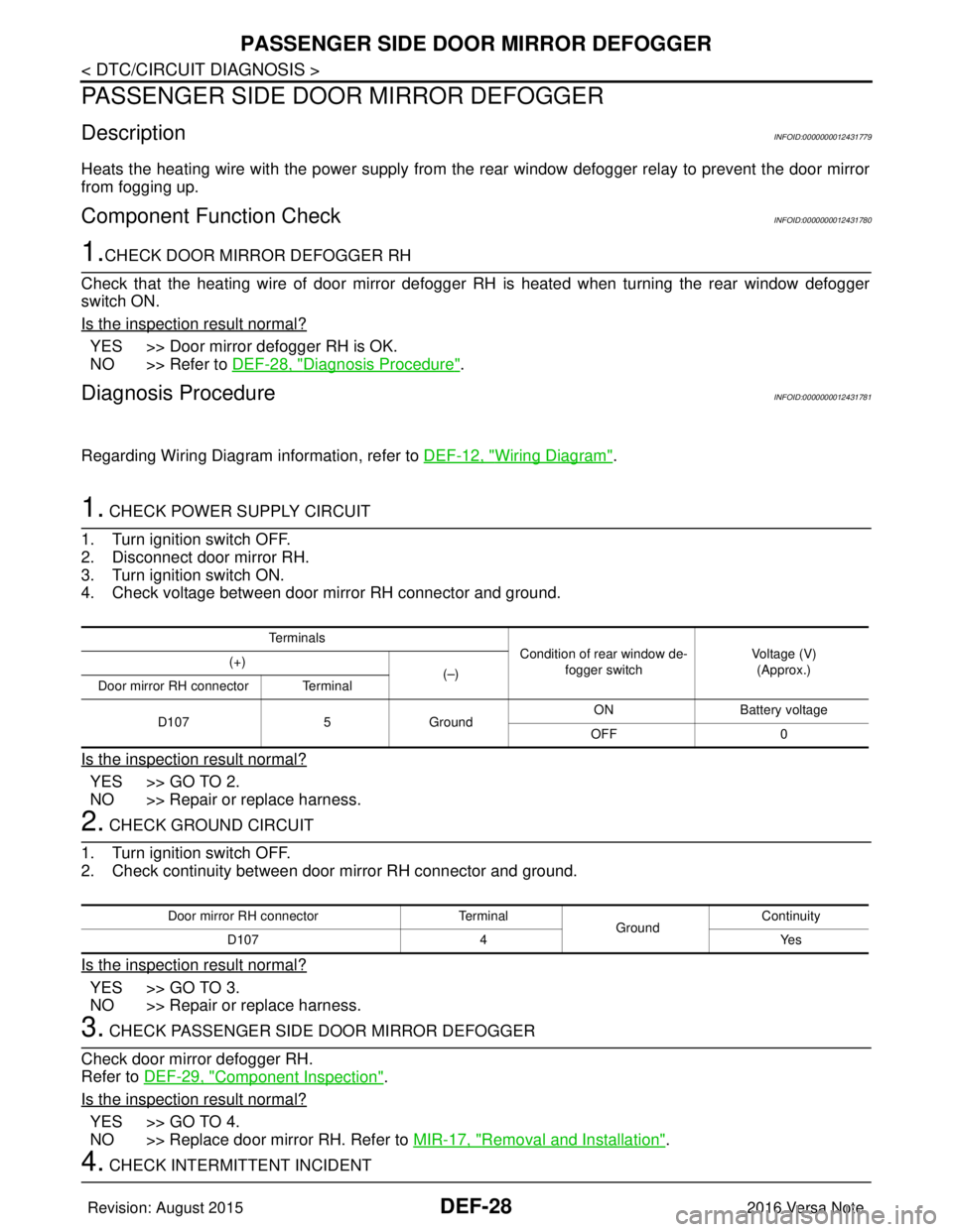
1. CHECK POWER SUPPLY CIRCUIT
1. Turn ignition switch OFF.
2. Disconnect door mirror RH.
3. Turn ignition switch ON.
4. Check voltage between door mirror RH connector and ground.
Is the inspection result normal?
YES >> GO TO 2.
NO >> Repair or replace harness.
2. CHECK GROUND CIRCUIT
1. Turn ignition switch OFF.
2. Check continuity between door mirror RH connector and ground.
Is the inspection result normal?
YES >> GO TO 3.
NO >> Repair or replace harness.
3. CHECK PASSENGER SIDE DOOR MIRROR DEFOGGER
Check door mirror defogger RH.
Refer to DEF-29, "
Component Inspection".
Is the inspection result normal?
YES >> GO TO 4.
NO >> Replace door mirror RH. Refer to MIR-17, "
Removal and Installation".
4. CHECK INTERMITTENT INCIDENT
Te r m i n a l s
Condition of rear window de-
fogger switch Voltage (V)
(Approx.)
(+)
(–)
Door mirror RH connector Terminal
D107 5Ground ON
Battery voltage
OFF 0
Door mirror RH connector Terminal
GroundContinuity
D107 4 Yes
Revision: August 2015 2016 Versa Note
cardiagn.com
Page 691 of 3641

DLK-2
DOOR LOCK .............................................................31
DOOR LOCK : CONSULT Function (BCM -
DOOR LOCK) .........................................................
31
INTELLIGENT KEY ................................................ ...31
INTELLIGENT KEY : CONSULT Function (BCM -
INTELLIGENT KEY) ...............................................
31
ECU DIAGNOSIS INFORMATION ........... ...35
BCM ................................................................ ...35
List of ECU Reference ......................................... ...35
WIRING DIAGRAM .....................................36
POWER DOOR LOCK SYSTEM .................... ...36
Wiring Diagram .................................................... ...36
INTELLIGENT KEY SYSTEM ............................46
Wiring Diagram .................................................... ...46
BASIC INSPECTION ...................................61
DIAGNOSIS AND REPAIR WORK FLOW ..... ...61
Work Flow ............................................................ ...61
INSPECTION AND ADJUSTMENT ...................64
ADDITIONAL SERVICE WHEN REPLACING
CONTROL UNIT (BCM) ......................................... ...
64
ADDITIONAL SERVICE WHEN REPLACING
CONTROL UNIT (BCM) : Description ................. ...
64
ADDITIONAL SERVICE WHEN REPLACING
CONTROL UNIT (BCM) : Work Procedure ......... ...
64
DTC/CIRCUIT DIAGNOSIS ...................... ...65
B2621 INSIDE ANTENNA .............................. ...65
DTC Logic ............................................................ ...65
Diagnosis Procedure ..............................................65
B2622 INSIDE ANTENNA .................................67
DTC Logic ............................................................ ...67
Diagnosis Procedure ..............................................67
B2623 INSIDE ANTENNA .................................69
DTC Logic ............................................................ ...69
Diagnosis Procedure ..............................................69
B2626 OUTSIDE ANTENNA .............................71
DTC Logic ............................................................ ...71
Diagnosis Procedure ..............................................71
B2627 OUTSIDE ANTENNA .............................73
DTC Logic ............................................................ ...73
Diagnosis Procedure ..............................................73
B2628 OUTSIDE ANTENNA .............................75
DTC Logic ............................................................ ...75
Diagnosis Procedure ..............................................75
POWER SUPPLY AND GROUND CIRCUIT .....77
BCM ........................................................................ ...77
BCM : Diagnosis Procedure ....................................77
COMBINATION METER BUZZER ....................78
Component Function Check ............................... ...78
Diagnosis Procedure ...............................................78
DOOR LOCK ACTUATOR ................................79
DRIVER SIDE ......................................................... ...79
DRIVER SIDE : Component Function Check ........79
DRIVER SIDE : Diagnosis Procedure .....................79
PASSENGER SIDE ...................................................80
PASSENGER SIDE :
Component Function Check ............................... ...
80
PASSENGER SIDE : Diagnosis Procedure ............80
REAR LH ................................................................ ...81
REAR LH : Component Function Check ...............81
REAR LH : Diagnosis Procedure ............................81
REAR RH ................................................................ ...82
REAR RH : Component Function Check ...............82
REAR RH : Diagnosis Procedure ...........................82
BACK DOOR .......................................................... ...83
BACK DOOR : Description .....................................83
BACK DOOR : Component Function Check .........83
BACK DOOR : Diagnosis Procedure ......................84
BACK DOOR LOCK ACTUATOR RELAY .......86
Description ........................................................... ...86
Component Function Check ...................................86
Diagnosis Procedure ...............................................86
Component Inspection ............................................87
DOOR LOCK AND UNLOCK SWITCH .............89
Component Function Check ............................... ...89
Diagnosis Procedure ...............................................89
Component Inspection ............................................90
UNLOCK SENSOR ............................................92
Component Function Check ............................... ...92
Diagnosis Procedure ...............................................92
Component Inspection ............................................93
DOOR REQUEST SWITCH ...............................94
Component Function Check ..................................94
Diagnosis Procedure ...............................................94
Component Inspection ............................................95
BACK DOOR REQUEST SWITCH ...................96
Description ........................................................... ...96
Component Function Check ..................................96
Diagnosis Procedure ...............................................96
Component Inspection ............................................97
DOOR SWITCH .................................................98
Component Function Check ............................... ...98
Diagnosis Procedure ...............................................98
Component Inspection ............................................99
Revision: August 2015 2016 Versa Note
cardiagn.com
Page 695 of 3641

DLK-6
REMOTE KEYLESS ENTRY SYSTEM : System
Diagram .................................................................
199
REMOTE KEYLESS ENTRY SYSTEM : System
Description .............................................................
199
DIAGNOSIS SYSTEM (BCM) ..........................201
COMMON ITEM ..................................................... ..201
COMMON ITEM : CONSULT Function (BCM -
COMMON ITEM) ...................................................
201
DOOR LOCK .......................................................... ..202
DOOR LOCK : CONSULT Function (BCM -
DOOR LOCK) ........................................................
202
MULTI REMOTE ENT ............................................ ..202
MULTI REMOTE ENT : CONSULT Function
(BCM - MULTI REMOTE ENT) ..............................
203
ECU DIAGNOSIS INFORMATION .............205
BCM, IPDM E/R .............................................. .205
List of ECU Reference ......................................... ..205
WIRING DIAGRAM ....................................206
POWER DOOR LOCK SYSTEM .................... .206
Wiring Diagram .................................................... ..206
REMOTE KEYLESS ENTRY SYSTEM ...........216
Wiring Diagram .................................................... ..216
BASIC INSPECTION ..................................225
DIAGNOSIS AND REPAIR WORKFLOW ...... .225
Work Flow ............................................................ ..225
INSPECTION AND ADJUSTMENT .................228
ADDITIONAL SERVICE WHEN REPLACING
CONTROL UNIT ..................................................... ..
228
ADDITIONAL SERVICE WHEN REPLACING
CONTROL UNIT : Description ............................. ..
228
ADDITIONAL SERVICE WHEN REPLACING
CONTROL UNIT : Special Repair Requirement ....
228
DTC/CIRCUIT DIAGNOSIS ...................... ..229
U1000 CAN COMM ......................................... .229
Description ........................................................... ..229
DTC Logic ..............................................................229
Diagnosis Procedure .............................................229
U1010 CONTROL UNIT (CAN) .......................230
DTC Logic ............................................................ ..230
Diagnosis Procedure .............................................230
POWER SUPPLY AND GROUND CIRCUIT ...231
BCM ........................................................................ ..231
BCM : Diagnosis Procedure ..................................231
DOOR SWITCH ...............................................232
Description ........................................................... ..232
Component Function Check ............................... .232
Diagnosis Procedure .............................................232
Component Inspection ..........................................234
DOOR LOCK AND UNLOCK SWITCH ............235
DRIVER SIDE ......................................................... .235
DRIVER SIDE : Description ..................................235
DRIVER SIDE : Component Function Check ......235
DRIVER SIDE : Diagnosis Procedure ...................235
PASSENGER SIDE .................................................236
PASSENGER SIDE : Descripti on .........................236
PASSENGER SIDE :
Component Function Check ............................... .
236
PASSENGER SIDE : Diagnosis Procedure ..........237
KEY CYLINDER SWITCH ................................239
Description ........................................................... .239
Component Function Check .................................239
Diagnosis Procedure .............................................239
Component Inspection ..........................................240
KEY SWITCH (BCM INPUT) ............................241
Diagnosis Procedure ............................................ .241
DOOR LOCK ACTUATOR ...............................242
DRIVER SIDE ......................................................... .242
DRIVER SIDE : Description ..................................242
DRIVER SIDE : Component Function Check ......242
DRIVER SIDE : Diagnosis Procedure ...................242
PASSENGER SIDE .................................................243
PASSENGER SIDE : Descripti on .........................243
PASSENGER SIDE :
Component Function Check ............................... .
243
PASSENGER SIDE : Diagnosis Procedure ..........243
REAR LH ................................................................ .244
REAR LH : Description .........................................244
REAR LH : Component Function Check ............ .244
REAR LH : Diagnosis Procedure ..........................244
REAR RH ................................................................ .245
REAR RH : Description .........................................245
REAR RH : Component Function Check .............245
REAR RH : Diagnosis Procedure .........................246
REMOTE KEYLESS ENTRY RECEIVER ........247
Description ........................................................... .247
Component Function Check ................................247
Diagnosis Procedure .............................................247
KEYFOB BATTERY AND FUNCTION .............250
Description ........................................................... .250
Component Function Check ................................250
Diagnosis Procedure .............................................250
HORN FUNCTION ............................................252
Description ........................................................... .252
Component Function Check ................................252
Revision: August 2015 2016 Versa Note
cardiagn.com
Page 698 of 3641
![NISSAN NOTE 2016 Service Repair Manual PRECAUTIONSDLK-9
< PRECAUTION > [WITH INTELLIGENT KEY SYSTEM]
C
D
E
F
G H
I
J
L
M A
B
DLK
N
O P
PRECAUTION
PRECAUTIONS
Precaution for Supplemental Restraint System (SRS) "AIR BAG" and "SEAT BELT
PRE NISSAN NOTE 2016 Service Repair Manual PRECAUTIONSDLK-9
< PRECAUTION > [WITH INTELLIGENT KEY SYSTEM]
C
D
E
F
G H
I
J
L
M A
B
DLK
N
O P
PRECAUTION
PRECAUTIONS
Precaution for Supplemental Restraint System (SRS) "AIR BAG" and "SEAT BELT
PRE](/manual-img/5/57363/w960_57363-697.png)
PRECAUTIONSDLK-9
< PRECAUTION > [WITH INTELLIGENT KEY SYSTEM]
C
D
E
F
G H
I
J
L
M A
B
DLK
N
O P
PRECAUTION
PRECAUTIONS
Precaution for Supplemental Restraint System (SRS) "AIR BAG" and "SEAT BELT
PRE-TENSIONER"
INFOID:0000000012429960
The Supplemental Restraint System such as “AIR BAG” and “SEAT BELT PRE-TENSIONER”, used along
with a front seat belt, helps to reduce the risk or severi ty of injury to the driver and front passenger for certain
types of collision. Information necessary to service the system safely is included in the SR and SB section of
this Service Manual.
WARNING:
• To avoid rendering the SRS inoper ative, which could increase the risk of personal injury or death in
the event of a collision which would result in air bag inflation, all maintenance must be performed by
an authorized NISSAN/INFINITI dealer.
• Improper maintenance, including in correct removal and installation of the SRS, can lead to personal
injury caused by unintentional act ivation of the system. For removal of Spiral Cable and Air Bag
Module, see the SR section.
• Do not use electrical test equipm ent on any circuit related to the SRS unless instructed to in this
Service Manual. SRS wiring harnesses can be identi fied by yellow and/or orange harnesses or har-
ness connectors.
PRECAUTIONS WHEN USING POWER TOOLS (AIR OR ELECTRIC) AND HAMMERS
WARNING:
• When working near the Airbag Diagnosis Sensor Un it or other Airbag System sensors with the Igni-
tion ON or engine running, DO NOT use air or el ectric power tools or strike near the sensor(s) with a
hammer. Heavy vibration could activate the sensor( s) and deploy the air bag(s), possibly causing
serious injury.
• When using air or electric power tools or hammers, always switch the Ignition OFF, disconnect the
battery and wait at least three mi nutes before performing any service.
Procedure without Cowl Top CoverINFOID:0000000012429961
When performing the procedure after removing cowl top cover, cover
the lower end of windshield with urethane, etc. to prevent damage to
the windshield.
Precaution for Servicing Doors and LocksINFOID:0000000012429962
WARNING:
Radio waves could adversely affect electric medical equipment. Those who use a pacemaker should
contact the electric medical equipment manufacturer for the possible influences before use,
• After removing and installing the opening/closing parts, be sure to carry out fitting adjustments to check their operation.
• Check the lubrication level, damage, and wear of each part. If necessary, grease or replace it.
• When removing or disassembling each component, be ca reful not to damage or deform it. If a component
may be subject to interference, be sure to protect it with a shop cloth.
• When removing (disengaging) components with a screwdriver or similar tool, be sure to wrap the component
with a shop cloth or vinyl tape to protect it.
• Protect the removed parts with a shop cloth and prevent them from being dropped.
• Replace a deformed or damaged clip.
• If a part is specified as a non-reusabl e part, always replace it with a new one.
PIIB3706J
Revision: August 2015 2016 Versa Note
cardiagn.com
Page 725 of 3641
![NISSAN NOTE 2016 Service Repair Manual DLK-36
< WIRING DIAGRAM >[WITH INTELLIGENT KEY SYSTEM]
POWER DOOR LOCK SYSTEM
WIRING DIAGRAM
POWER DOOR LOCK SYSTEM
Wiring DiagramINFOID:0000000012429993
AAKWA0963GB
Revision: August 2015
2016 Versa N NISSAN NOTE 2016 Service Repair Manual DLK-36
< WIRING DIAGRAM >[WITH INTELLIGENT KEY SYSTEM]
POWER DOOR LOCK SYSTEM
WIRING DIAGRAM
POWER DOOR LOCK SYSTEM
Wiring DiagramINFOID:0000000012429993
AAKWA0963GB
Revision: August 2015
2016 Versa N](/manual-img/5/57363/w960_57363-724.png)
DLK-36
< WIRING DIAGRAM >[WITH INTELLIGENT KEY SYSTEM]
POWER DOOR LOCK SYSTEM
WIRING DIAGRAM
POWER DOOR LOCK SYSTEM
Wiring DiagramINFOID:0000000012429993
AAKWA0963GB
Revision: August 2015
2016 Versa Note
cardiagn.com