2016 MERCEDES-BENZ SL ROADSTER clock
[x] Cancel search: clockPage 87 of 333

For all countries except the United Kingdom:
you can open a door from inside the vehicle evenif it has been locked.
United Kingdom only: you can only open a
door from inside the vehicle if the double-lock
function has been deactivated. You can deacti-
vate the double lock function by deactivating the
interior motion sensor (Y page 75).
When a locked door is opened from inside the
vehicle, the previous unlocking process will be
observed if the vehicle has been:
R locked with the locking button for the central
locking or
R locked automatically
The vehicle will be fully unlocked if it had previ-
ously been fully unlocked. Only the door which
has been opened from the inside is unlocked if
only the driver's door had been previously
unlocked. Automatic locking feature
X
To deactivate: press and hold button :for
about five seconds until a tone sounds.
X To activate: press and hold button ;for
about five seconds until a tone sounds.
If you press one of the two buttons and do not
hear a tone, the relevant setting has already
been selected.
The vehicle is locked automatically when the
ignition is switched on and the wheels are turn-
ing.
You could therefore be locked out if:
R the vehicle is being pushed
R the vehicle is being towed
R the vehicle is being tested on a dynamometer You can also activate and deactivate the auto-
matic locking function using the on-board com-
puter (Y page 211). Power closing
Power closing pulls the doors and boot lid into
their locks automatically even if they are only
partly closed. X Power closing feature (doors): push the
door past the first detent position into the
lock.
Power closing will pull the door fully closed.
X To power close the boot lid: lightly push the
boot lid closed.
The power closing function pulls the boot lid
closed. Unlocking/locking the driver's door
using the emergency key element
i In order to lock all of the vehicle's locks,
begin by pressing the button for locking the
vehicle from the inside while the driver's door
is open. Then proceed to unlock the driver's
door using the emergency key element. X
To unlock: turn the emergency key element
anti-clockwise as far as it will go to position
1.
X To lock: turn the emergency key element
clockwise as far as it will go to position 1.
Right-hand-drive vehicle: turn the emergency
key element in the opposite direction in both
cases.
If you use the emergency key element to unlock
and open the driver's door, the anti-theft alarm
system will be triggered. Switch off the alarm
(Y page 74). 84
DoorsOpening and closing
Page 92 of 333
X
To open: pull remote operating switch :for
the boot lid until the boot lid opens.
If the boot separator was closed, it opens
automatically and remains open.
X To close: press remote operating switch :
for the boot lid until the boot lid is closed.
When the roof is open, the boot separator
closes automatically.
You can open and close the boot lid from the
driver's seat when the vehicle is stationary and
unlocked. Locking the boot separately
The separate boot locking function is only avail-
able in certain countries.
You can lock the boot separately. If you then
unlock the vehicle centrally, the boot remains
locked and cannot be opened.
X Close the boot lid.
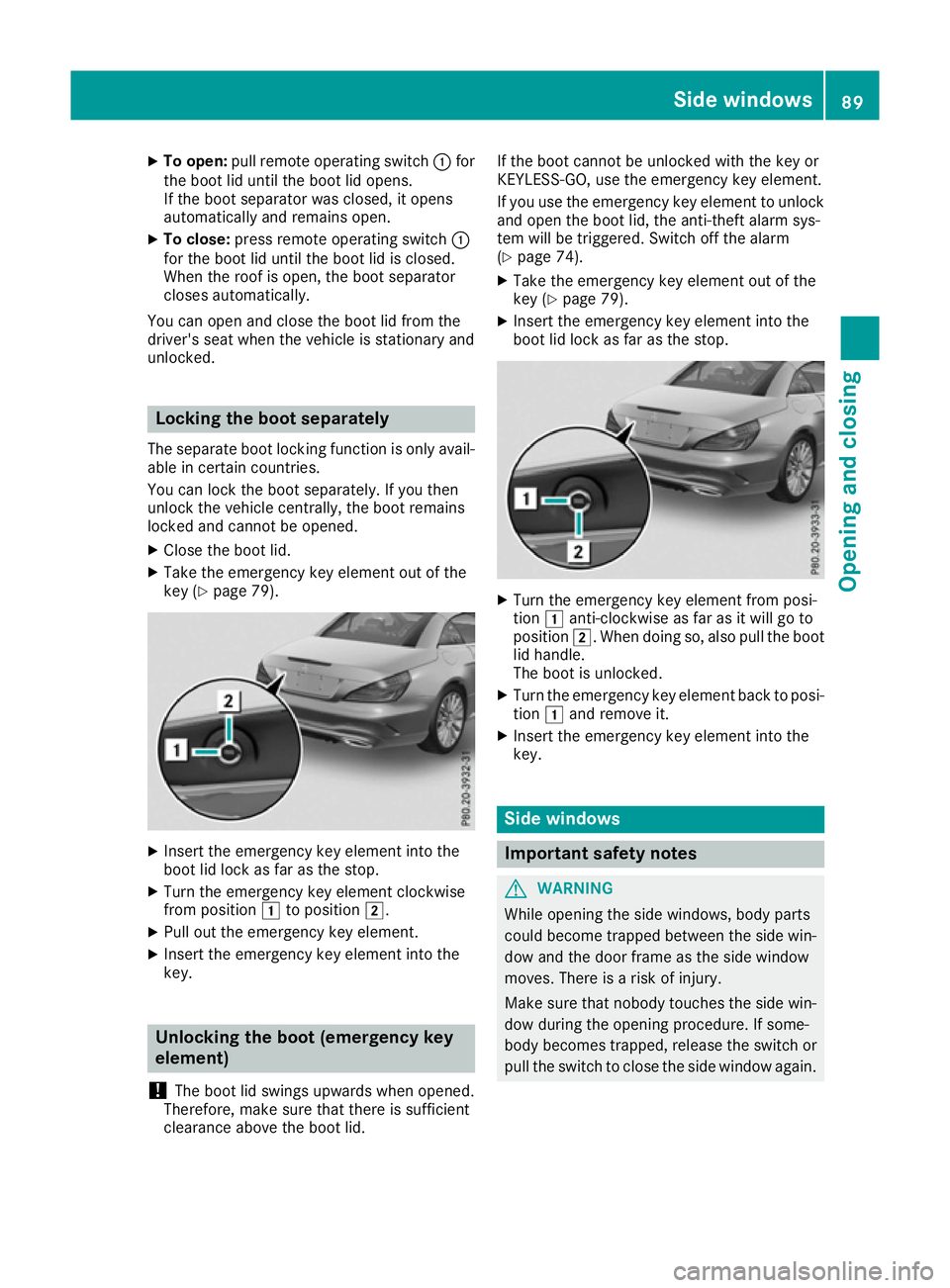
X Take the emergency key element out of the
key (Y page 79). X
Insert the emergency key element into the
boot lid lock as far as the stop.
X Turn the emergency key element clockwise
from position 1to position 2.
X Pull out the emergency key element.
X Insert the emergency key element into the
key. Unlocking the boot (emergency key
element)
! The boot lid swings upwards when opened.
Therefore, make sure that there is sufficient
clearance above the boot lid. If the boot cannot be unlocked with the key or
KEYLESS-GO, use the emergency key element.
If you use the emergency key element to unlock
and open the boot lid, the anti-theft alarm sys-
tem will be triggered. Switch off the alarm
(Y page 74).
X Take the emergency key element out of the
key (Y page 79).
X Insert the emergency key element into the
boot lid lock as far as the stop. X
Turn the emergency key element from posi-
tion 1anti-clockwise as far as it will go to
position 2. When doing so, also pull the boot
lid handle.
The boot is unlocked.
X Turn the emergency key element back to posi-
tion 1and remove it.
X Insert the emergency key element into the
key. Side windows
Important safety notes
G
WARNING
While opening the side windows, body parts
could become trapped between the side win- dow and the door frame as the side window
moves. There is a risk of injury.
Make sure that nobody touches the side win-
dow during the opening procedure. If some-
body becomes trapped, release the switch or pull the switch to close the side window again. Side windows
89Opening and closing Z
Page 128 of 333
Problems with the "Cooling with air dehumidification" function
Problem
Possible causes/consequences and
M
MSolutions The indicator lamp in the
¿ button flashes
three times or remains
off. The cooling with air
dehumidification func-
tion cannot be activated. The cooling with air dehumidification function has been deactivated
due to a malfunction.
X Consult a qualified specialist workshop. Setting climate control to automatic
mode
General notes In automatic mode, the set temperature is main-
tained automatically at a constant level. The
system automatically regulates the temperature of the dispensed air, the airflow and the air dis- tribution.
The automatic mode functions optimally when
the "Cooling with air dehumidification" function is activated. If desired, cooling with air dehu-
midification can be deactivated.
If you deactivate the "Cooling with air dehumid-
ification" function, the air inside the vehicle will not be cooled. The air inside the vehicle will also
not be dehumidified. The windows can mist up
more quickly. Therefore, deactivate the "Cooling
with air dehumidification" function only briefly.
Automatic control X
Turn the key to position 2in the ignition lock
(Y page 132).
X Set the desired temperature.
X To activate: press theÃbutton.
The indicator lamp in the Ãbutton lights
up. Automatic air distribution and airflow are
activated.
i When automatic mode is enabled, the cli-
mate mode can be selected (Y page 125).
X To switch to manual mode: press the_
button.
or X Press the IorK button.
The indicator lamp in the Ãbutton goes
out. Setting the climate mode
In automatic mode you can select the following
climate modes:
FOCUS high airflow, slightly cooler setting
MEDIUM medium airflow, standard setting
DIFFUSE low airflow, slightly warmer and draught-free setting
X Turn the key to position 2in the ignition lock
(Y page 132).
X Press the Ãbutton.
X Press the ñbutton repeatedly until the
desired climate mode appears in the display. Setting the temperature
Switching on/off Different temperatures can be set for the driv-
er's and front-passenger sides.
X Turn the key to position 2in the ignition lock
(Y page 132).
X Turn control :or; anti-clockwise or clock-
wise.
Only change the temperature setting in small
increments. Start at 22 †.
i If you turn controls
:and ;anti-clock-
wise to the lowest temperature setting, air-
recirculation mode may switch on automati-
cally, depending on the outside temperature. Operating the climate control system
125Climate control
Page 129 of 333
Setting the air distribution
Activating/deactivating X
Turn the key to position 2in the ignition lock
(Y page 132).
X Press the _button repeatedly until the
desired symbol appears in the display.
Air distribution settings The air distribution can be set to the following
positions:
P Directs the airflow through the centre
and side air vents
O Directs the airflow through the footwell
air vents
S Directs the airflow through the centre
and side air vents as well as the footwell
air vents
¯ Directs the airflow through the demister
vents
b Directs the airflow through the centre
and side air vents as well as the demister
vents
a Directs the airflow through the footwell
and demister vents
_ Directs the airflow through the demister
vents, the centre and side air vents as
well as the footwell air vents
i Regardless of the air distribution setting,
airflow is always directed through the side air
vents. The side air vents can only be closed
when the adjuster in the side air vent is turned clockwise. Setting the airflow
Activating/deactivating X
Turn the key to position 2in the ignition lock
(Y page 132).
X To increase: press theKbutton.
X To reduce: press theIbutton. Switching the ZONE function on/off
X To switch on: press theábutton.
The indicator lamp in the ábutton lights
up. The temperature setting for the driver's side is not adopted for the front-passenger
side.
X To switch off: press theábutton.
The indicator lamp in the ábutton goes
out. The temperature setting for the driver's
side is adopted for the front-passenger side. Demisting the windscreen
General notes You can use this function to defrost the wind-
screen or to demist the inside of the windscreen
and the side windows.
Switch off the windscreen demisting function as
soon as the windscreen is clear again.
Switching the "Windscreen demisting"
function on or off X
Turn the key to position 2in the ignition lock
(Y page 132).
X To switch on: press the¬button.
The indicator lamp in the ¬button lights
up.
The climate control system switches to the
following functions:
R high airflow
R high temperature
R air distribution to the windscreen and front
side windows
R air-recirculation mode off
X To switch off: press the¬button.
The indicator lamp in the ¬button goes
out. The previous settings are reactivated.
Air-recirculation mode remains deactivated.
or X Press the Ãbutton.
The indicator lamp in the ¬button goes
out. Airflow and air distribution are set to
automatic mode.
or X Turn temperature control :orD anti-clock-
wise or clockwise (Y page 123).
or X Press the KorI button. 126
Operating the climate control systemClimate control
Page 155 of 333
Do not get into the vehicle again during the refu-
elling process. Otherwise, electrostatic charge
could build up again.
! Do not use diesel to refuel vehicles with a
petrol engine. Do not switch on the ignition if you accidentally refuel with the wrong fuel.
Otherwise, the fuel will enter the fuel system.
Even small amounts of the wrong fuel can
result in damage to the fuel system and the
engine. Notify a qualified specialist workshop
and have the fuel tank and fuel lines drained
completely.
! Overfilling the fuel tank could damage the
fuel system.
! Take care not to spill any fuel on painted
surfaces. You could otherwise damage the
paintwork.
! Use a filter when adding fuel from a fuel can.
The fuel lines and/or the fuel injection system could otherwise be blocked by particles fromthe fuel can.
If you overfill the fuel tank, some fuel may spray
out when you remove the fuel pump nozzle.
Further information on fuel and fuel quality
(Y page 322). Refuelling
General notes The fuel filler flap is unlocked or locked auto-
matically when you unlock or lock the vehicle
with the key or using KEYLESS-GO.
The position of the
8fuel filler cap is dis-
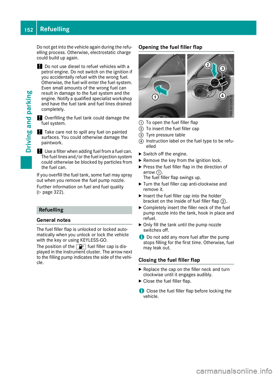
played in the instrument cluster. The arrow next to the filling pump indicates the side of the vehi- cle. Opening the fuel filler flap :
To open the fuel filler flap
; To insert the fuel filler cap
= Tyre pressure table
? Instruction label on the fuel type to be refu-
elled
X Switch off the engine.
X Remove the key from the ignition lock.
X Press the fuel filler flap in the direction of
arrow :.
The fuel filler flap swings up.
X Turn the fuel filler cap anti-clockwise and
remove it.
X Insert the fuel filler cap into the holder
bracket on the inside of fuel filler flap ;.
X Completely insert the filler neck of the fuel
pump nozzle into the tank, hook in place and
refuel.
X Only fill the tank until the pump nozzle
switches off.
i Do not add any more fuel after the pump
stops filling for the first time. Otherwise, fuel
may leak out.
Closing the fuel filler flap X
Replace the cap on the filler neck and turn
clockwise until it engages audibly.
X Close the fuel filler flap.
i Close the fuel filler flap before locking the
vehicle. 152
RefuellingDriving an
d parking
Page 202 of 333
Important safety notes
G
WARNING
Operating the integrated information systems and communications equipment in the vehicle
while driving will distract you from traffic con-
ditions. You could then lose control of the
vehicle. There is a risk of an accident.
Only operate these devices if road traffic con-
ditions permit. If you are unsure about the
surrounding conditions, pull over to a safe
location and make entries only while the vehi-
cle is stationary.
You must observe the legal requirements for the country in which you are currently driving whenoperating the on-board computer. G
WARNING
If the instrument cluster has failed or mal-
functioned, you may not recognise function
restrictions relevant to safety. The operating
safety of your vehicle may be impaired. There is a risk of an accident.
Drive on carefully. Have the vehicle checked
at a qualified specialist workshop immedi-
ately.
The on-board computer only shows messages or warnings from certain systems in the multifunc-tion display. You should therefore make sure
your vehicle is operating safely at all times.
If the operating safety of your vehicle is
impaired, park the vehicle safely as soon as pos- sible. Contact a qualified specialist workshop.
For an overview, see the instrument cluster illus-
tration (Y page 32). Displays and operation
Instrument cluster lighting
The lighting in the instrument cluster, in the dis- plays and the controls in the vehicle interior can
be adjusted using the brightness control knob.
The brightness control knob is located on the
bottom left of the instrument cluster
(Y page 32). X
Turn the brightness control knob clockwise or
anti-clockwise.
If you turn the light switch (Y page 113) to the
Ã, TorL position, the brightness
will depend upon the brightness of the ambi-
ent light.
The light sensor in the instrument cluster
automatically controls the brightness of the
multifunction display. In daylight, the displays in the instrument cluster are not illuminated. Speedometer with segments
The segments in the speedometer indicate
which speed range is available.
R Cruise control activated (Y page 159):
The segments light up from the stored speed to the maximum speed.
R Variable speed limiter is activated
(Y page 170):
The segments light up from the start of the
scale to the selected limit speed.
R Distance Pilot DISTRONIC is activated
(Y page 161):
One or two segments in the set speed range
light up.
R Distance Pilot DISTRONIC detects a vehicle in
front moving more slowly than the stored
speed:
The segments between the speed of the vehi-
cle in front and the stored speed light up. Rev counter
! Do not drive in the overrevving range. Doing
so will damage the engine.
The red band in the rev counter indicates the
engine's overrevving range.
The fuel supply is interrupted to protect the
engine when the red band is reached. Outside temperature display
You should pay special attention to road condi-
tions when temperatures are around freezing
point.
Bear in mind that the outside temperature dis-
play indicates the measured air temperature
and not the road surface temperature. Displays and operation
199On-board computer and displays Z
Page 282 of 333
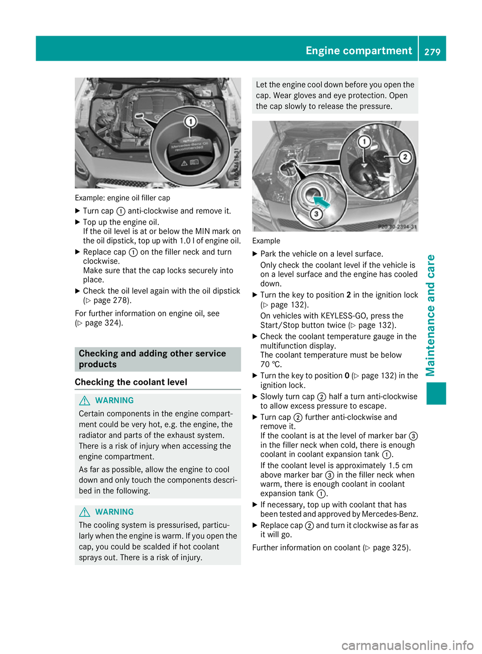
Example: engine oil filler cap
X Turn cap :anti-clockwise and remove it.
X Top up the engine oil.
If the oil level is at or below the MIN mark on
the oil dipstick, top up with 1.0 lof engine oil.
X Replace cap :on the filler neck and turn
clockwise.
Make sure that the cap locks securely into
place.
X Check the oil level again with the oil dipstick
(Y page 278).
For further information on engine oil, see
(Y page 324). Checking and adding other service
products
Checking the coolant level G
WARNING
Certain components in the engine compart-
ment could be very hot, e.g. the engine, the
radiator and parts of the exhaust system.
There is a risk of injury when accessing the
engine compartment.
As far as possible, allow the engine to cool
down and only touch the components descri- bed in the following. G
WARNING
The cooling system is pressurised, particu-
larly when the engine is warm. If you open the cap, you could be scalded if hot coolant
sprays out. There is a risk of injury. Let the engine cool down before you open the
cap. Wear gloves and eye protection. Open
the cap slowly to release the pressure. Example
X Park the vehicle on a level surface.
Only check the coolant level if the vehicle is
on a level surface and the engine has cooled
down.
X Turn the key to position 2in the ignition lock
(Y page 132).
On vehicles with KEYLESS-GO, press the
Start/Stop button twice (Y page 132).
X Check the coolant temperature gauge in the
multifunction display.
The coolant temperature must be below
70 †.
X Turn the key to position 0(Y page 132) in the
ignition lock.
X Slowly turn cap ;half a turn anti-clockwise
to allow excess pressure to escape.
X Turn cap ;further anti-clockwise and
remove it.
If the coolant is at the level of marker bar =
in the filler neck when cold, there is enough
coolant in coolant expansion tank :.
If the coolant level is approximately 1.5 cm
above marker bar =in the filler neck when
warm, there is enough coolant in coolant
expansion tank :.
X If necessary, top up with coolant that has
been tested and approved by Mercedes-Benz.
X Replace cap ;and turn it clockwise as far as
it will go.
Further information on coolant (Y page 325). Engine compartment
279Maintenance and care Z
Page 300 of 333
Do not use a rapid charging device to start the vehicle. If your vehicle's battery is discharged, the
engine can be jump-started from another vehicle or from a second battery using jump leads.
Observe the following points:
R The battery is not accessible in all vehicles. If the other vehicle's battery is not accessible, jump-
start the vehicle using a second battery or a jump-starting device.
R You may only jump-start the vehicle when the engine and exhaust system are cold.
R Do not start the engine if the battery is frozen. Let the battery thaw first.
R Jump-starting may only be performed using batteries with a nominal voltage of 12 V.
R Only use jump leads that have a sufficient cross-section and insulated terminal clamps.
R If the battery is fully discharged, leave the battery that is being used to jump-start connected for
a few minutes before attempting to start. This charges the empty battery a little.
R Make sure that the two vehicles do not touch.
Make sure that:
R The jump leads are not damaged.
R Non-insulated parts of the terminal clamps do not come into contact with other metal parts while
the jump leads are connected to the battery.
R The jump leads cannot come into contact with parts which can move when the engine is running,
such as the V-belt pulley or the fan.
X Secure the vehicle by applying the electric parking brake.
X Shift the transmission to position P.
X Make sure that the ignition is switched off . All indicator lamps in the instrument cluster must be
off. When using the key, turn the key to position 0in the ignition lock and remove it (Y page 132).
X Switch off all electrical consumers, e.g. rear window heating, lighting etc.
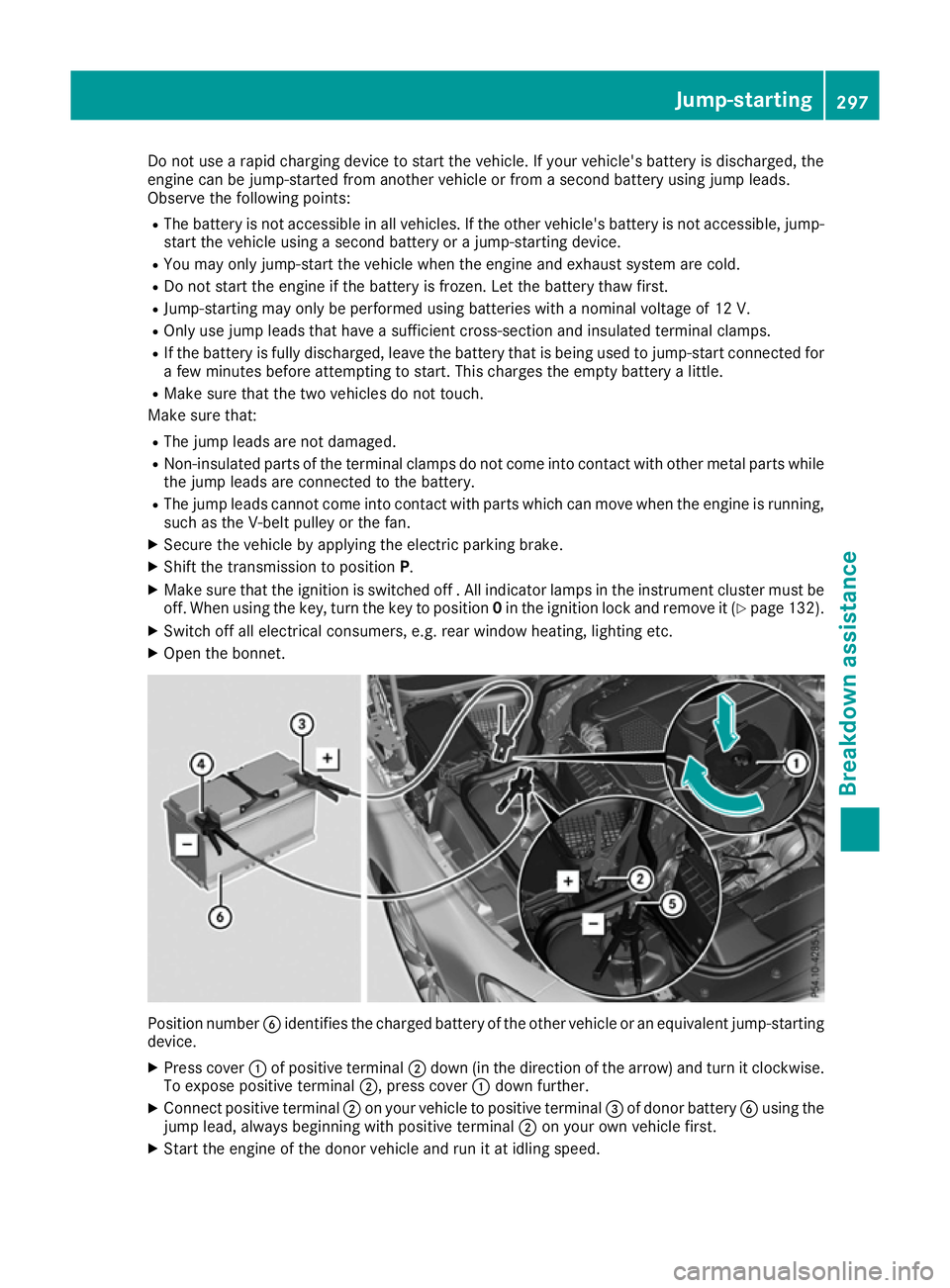
X Open the bonnet. Position number
Bidentifies the charged battery of the other vehicle or an equivalent jump-starting
device.
X Press cover :of positive terminal ;down (in the direction of the arrow) and turn it clockwise.
To expose positive terminal ;, press cover:down further.
X Connect positive terminal ;on your vehicle to positive terminal =of donor battery Busing the
jump lead, always beginning with positive terminal ;on your own vehicle first.
X Start the engine of the donor vehicle and run it at idling speed. Jump-starting
297Breakdown assistance Z