2016 MERCEDES-BENZ SL ROADSTER clock
[x] Cancel search: clockPage 302 of 333

For towing distances over 50 km, the entire
vehicle must be lifted up and transported.
! If you tow or tow-start another vehicle, its
weight must not exceed the maximum per-
missible gross vehicle weight of your vehicle.
Observe the legal requirements for the relevant countries when towing.
It is better to have the vehicle transported than
to have it towed.
The automatic transmission must be in position
N when the vehicle is being towed away.
The battery must be connected and charged.
Otherwise, you:
R cannot turn the key to position 2in the igni-
tion lock.
R cannot shift the automatic transmission to
position N.
Deactivate the automatic locking feature before towing the vehicle (Y page 211). You could oth-
erwise be locked out when pushing or towing
the vehicle.
Deactivate tow-away protection before the vehi-
cle is towed away (Y page 75). Fitting/removing the towing eye
Fitting the towing eye G
WARNING
The exhaust tail pipe may be extremely hot.
There is a risk of burning when removing the
rear cover.
Do not touch the exhaust tail pipe. Use
extreme caution when removing the rear
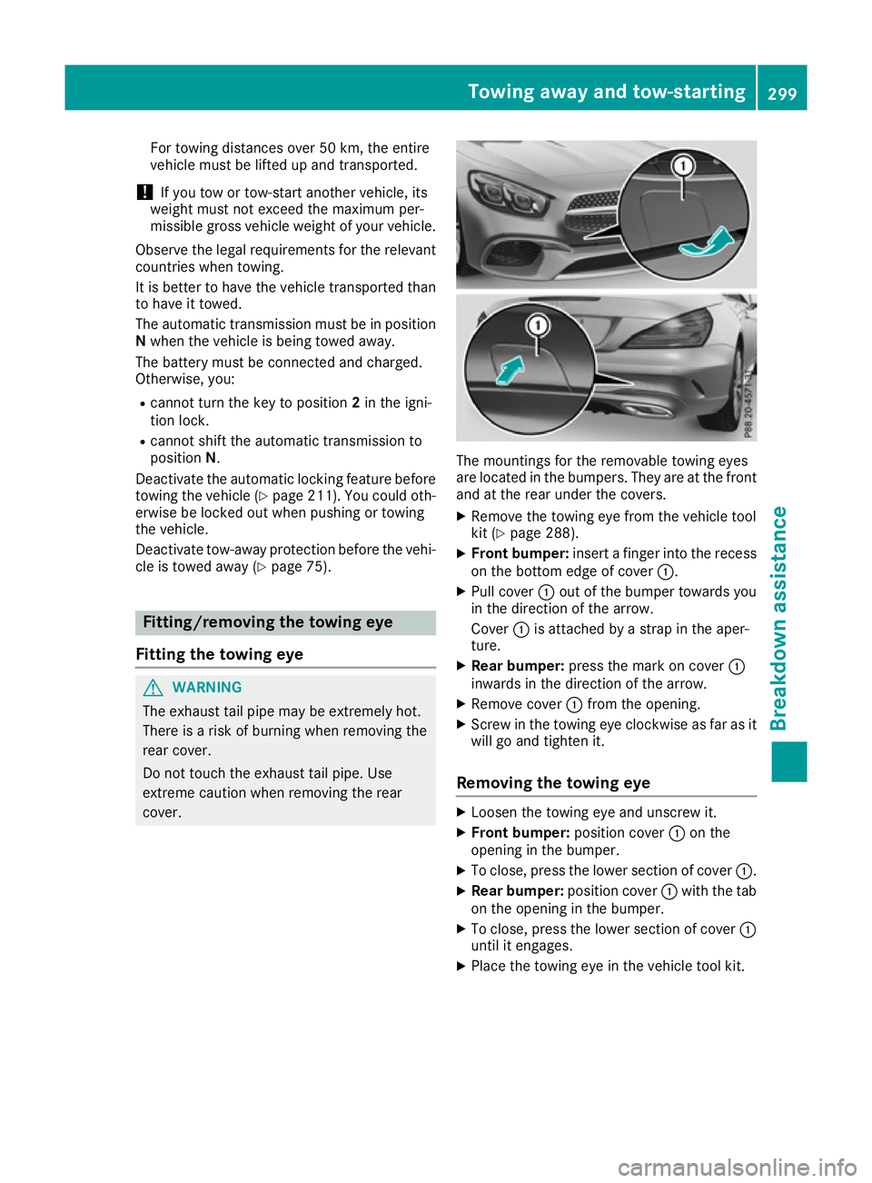
cover. The mountings for the removable towing eyes
are located in the bumpers. They are at the front and at the rear under the covers.
X Remove the towing eye from the vehicle tool
kit (Y page 288).
X Front bumper: insert a finger into the recess
on the bottom edge of cover :.
X Pull cover :out of the bumper towards you
in the direction of the arrow.
Cover :is attached by a strap in the aper-
ture.
X Rear bumper: press the mark on cover :
inwards in the direction of the arrow.
X Remove cover :from the opening.
X Screw in the towing eye clockwise as far as it
will go and tighten it.
Removing the towing eye X
Loosen the towing eye and unscrew it.
X Front bumper: position cover:on the
opening in the bumper.
X To close, press the lower section of cover :.
X Rear bumper: position cover:with the tab
on the opening in the bumper.
X To close, press the lower section of cover :
until it engages.
X Place the towing eye in the vehicle tool kit. Towing away and tow-starting
299Breakdown assistance Z
Page 317 of 333

must be positioned vertically, directly under
the jacking point of the vehicle.
Observe the following when raising the vehicle:
R only use the vehicle-specific jack that has
been tested and approved by Mercedes-Benz
to raise the vehicle. If the jack is used incor-
rectly, it could tip over while the vehicle is
raised.
R the jack is designed only to raise and hold the
vehicle for a short time while a wheel is being
changed. It is not permissible to use it to per- form maintenance work under the vehicle.
R avoid changing the wheel on uphill and down-
hill slopes.
R before raising the vehicle, safeguard it from
rolling away by applying the parking brake and
positioning wheel chocks. Do not release the parking brake while the vehicle is raised.
R the jack must be placed on a firm, flat and
non-slip surface. On a loose surface, a large,
flat load-bearing underlay must be used. On a
slippery surface, a non-slip underlay must be
used, e.g. rubber mats.
R do not use wooden blocks or similar objects
as a jack underlay. Otherwise, the jack will not
be able to achieve its load-bearing capacity
due to the restricted height.
R make sure that the distance between the
underside of the tyres and the ground does
not exceed 3 cm.
R never place your hands or feet under the
raised vehicle.
R do not lie under the vehicle.
R do not start the engine when the vehicle is
raised.
R do not open or close a door or the boot lid
when the vehicle is raised.
R make sure that no persons are present in the
vehicle when the vehicle is raised.
Vehicles with light-alloy wheels and hub
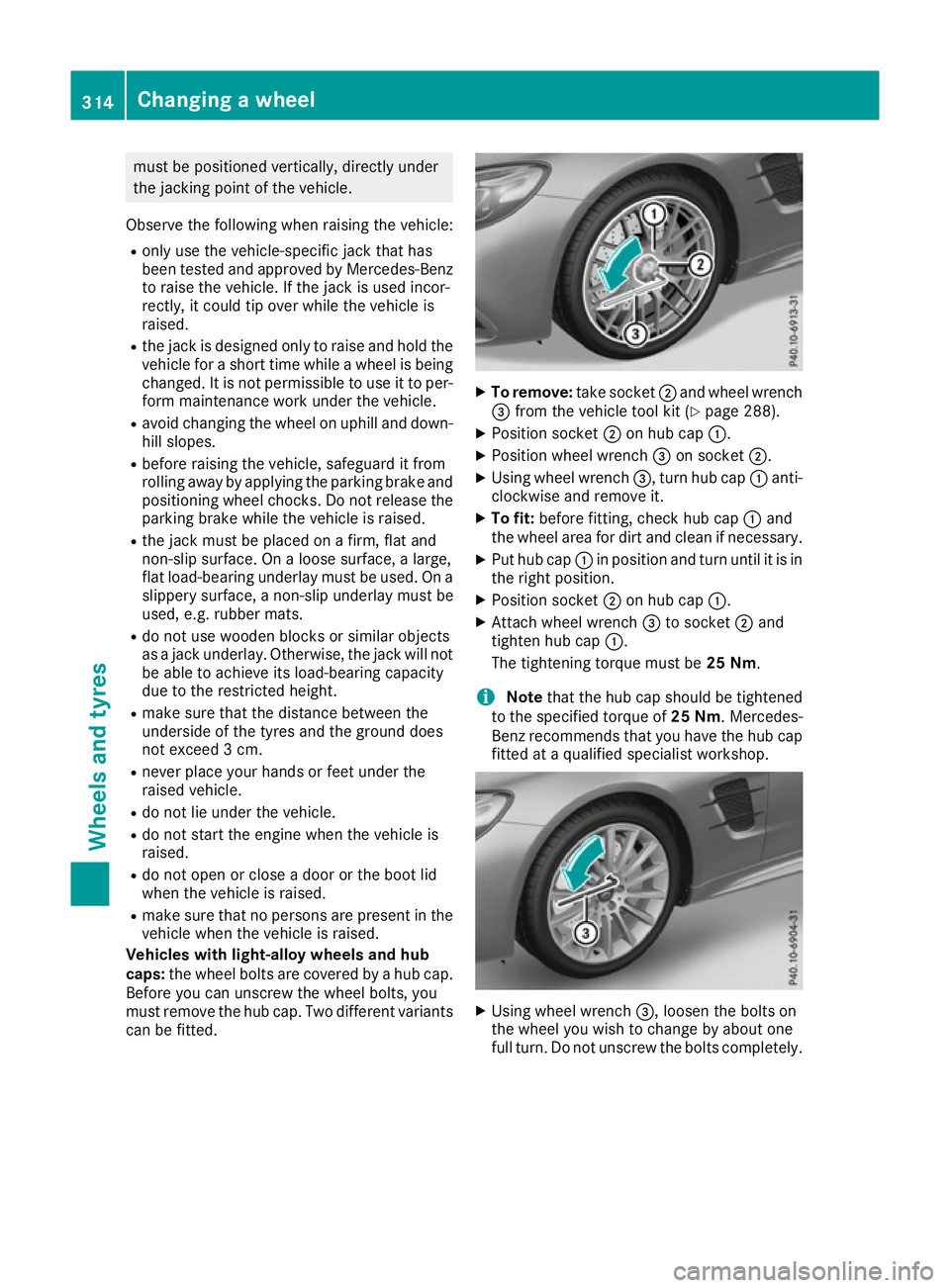
caps: the wheel bolts are covered by a hub cap.
Before you can unscrew the wheel bolts, you
must remove the hub cap. Two different variants
can be fitted. X
To remove: take socket;and wheel wrench
= from the vehicle tool kit (Y page 288).
X Position socket ;on hub cap :.
X Position wheel wrench =on socket ;.
X Using wheel wrench =, turn hub cap:anti-
clockwise and remove it.
X To fit: before fitting, check hub cap :and
the wheel area for dirt and clean if necessary.
X Put hub cap :in position and turn until it is in
the right position.
X Position socket ;on hub cap :.
X Attach wheel wrench =to socket ;and
tighten hub cap :.
The tightening torque must be 25 Nm.
i Note
that the hub cap should be tightened
to the specified torque of 25 Nm. Mercedes-
Benz recommends that you have the hub cap
fitted at a qualified specialist workshop. X
Using wheel wrench =, loosen the bolts on
the wheel you wish to change by about one
full turn. Do not unscrew the bolts completely. 314
Changing a wheelWheels and tyres
Page 318 of 333

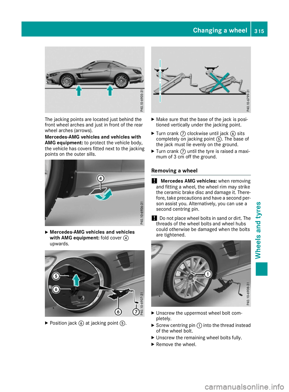
The jacking points are located just behind the
front wheel arches and just in front of the rear
wheel arches (arrows).
Mercedes-AMG vehicles and vehicles with
AMG equipment: to protect the vehicle body,
the vehicle has covers fitted next to the jacking
points on the outer sills. X
Mercedes-AMG vehicles and vehicles
with AMG equipment:
fold cover?
upwards. X
Position jack Bat jacking point A. X
Make sure that the base of the jack is posi-
tioned vertically under the jacking point.
X Turn crank Cclockwise until jack Bsits
completely on jacking point A. The base of
the jack must lie evenly on the ground.
X Turn crank Cuntil the tyre is raised a maxi-
mum of 3 cm off the ground.
Removing a wheel !
Mercedes AMG vehicles:
when removing
and fitting a wheel, the wheel rim may strike
the ceramic brake disc and damage it. There-
fore, take precautions and have a second per- son assist you. Alternatively, you can use a
second centring pin.
! Do not place wheel bolts in sand or dirt. The
threads of the wheel bolts and wheel hubs
could otherwise be damaged when the bolts
are tightened. X
Unscrew the uppermost wheel bolt com-
pletely.
X Screw centring pin :into the thread instead
of the wheel bolt.
X Unscrew the remaining wheel bolts fully.
X Remove the wheel. Changing a wheel
315Wheels and tyres Z
Page 319 of 333

Fitting a new wheel
G
WARNING
Oiled or greased wheel bolts or damaged
wheel bolts/hub threads can cause the wheel bolts to come loose. As a result, you could
lose a wheel while driving. There is a risk of
accident.
Never oil or grease wheel bolts. In the event ofdamage to the threads, contact a qualified
specialist workshop immediately. Have the
damaged wheel bolts or hub threads
replaced/renewed. Do not continue driving. G
WARNING
If you tighten the wheel bolts or wheel nuts
when the vehicle is raised, the jack could tip
over. There is a risk of injury.
Only tighten the wheel bolts or wheel nuts
when the vehicle is on the ground.
It is imperative to observe the instructions and
safety notes on "Changing a wheel"
(Y page 312).
Only use wheel bolts that have been designed
for the wheel and the vehicle. For safety rea-
sons, Mercedes-Benz recommends that you
only use wheel bolts which have been approved for Mercedes-Benz vehicles and the respective
wheel.
! Mercedes AMG vehicles:
when removing
and fitting a wheel, the wheel rim may strike
the ceramic brake disc and damage it. There-
fore, take precautions and have a second per- son assist you. Alternatively, you can use a
second centring pin. X
Clean the wheel and wheel hub contact sur-
faces.
X Slide the wheel to be mounted onto the cen-
tring pin and push it on.
X Tighten the wheel bolts until they are finger-
tight.
X Unscrew the centring pin.
X Tighten the last wheel bolt until it is finger-
tight.
X Vehicles with a collapsible emergency
spare wheel:
inflate the collapsible emer-
gency spare wheel (Y page 319).
Only then lower the vehicle.
Lowering the vehicle G
WARNING
The wheels could work loose if the wheel nuts and bolts are not tightened to the specified
tightening torque. There is a risk of accident.
Have the tightening torque immediately
checked at a qualified specialist workshop
after a wheel is changed.
! Vehicles with a collapsible emergency
spare wheel: Inflate the collapsible emer-
gency spare wheel using the tyre inflation
compressor before lowering the vehicle. The
rim could otherwise be damaged.
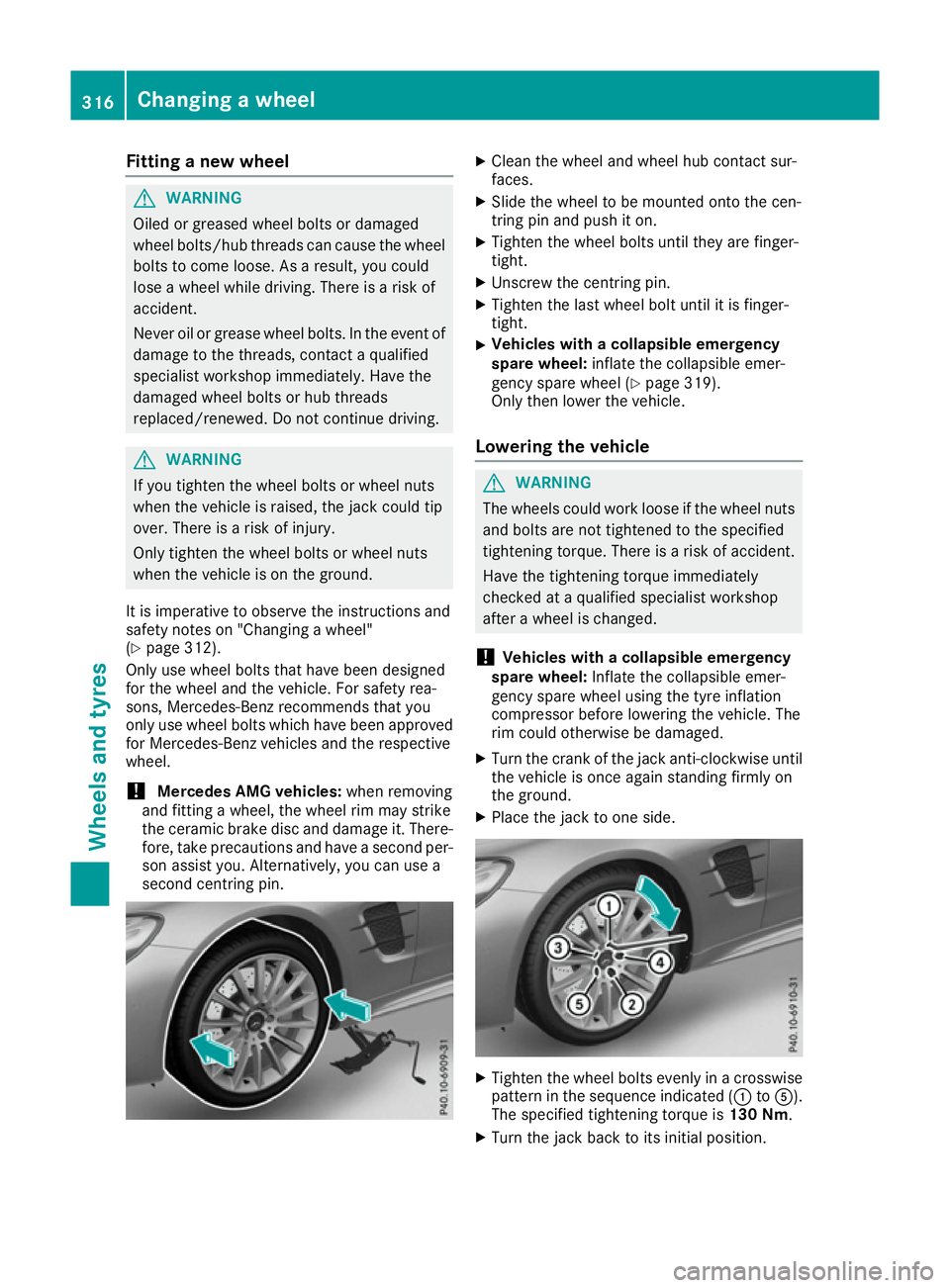
X Turn the crank of the jack anti-clockwise until
the vehicle is once again standing firmly on
the ground.
X Place the jack to one side. X
Tighten the wheel bolts evenly in a crosswise
pattern in the sequence indicated (: toA).
The specified tightening torque is 130 Nm.
X Turn the jack back to its initial position. 316
Changing a wheelWheels and ty
res