2016 MERCEDES-BENZ S-Class SEDAN change time
[x] Cancel search: change timePage 274 of 438
XUse: or9 to select the DriveAssistsubmenu.
XPressato confirm your selection.
XPress the :or9 button to select
Lane Keeping Assist.
XPress ato confirm.
The current selection, StandardorAdap‐tive, appears.
XTo change the setting: pressaagain.
For further information about Active Lane Keep-
ing Assist, see (
Ypage 237).
HYBRID submenu (PLUG-IN HYBRID
vehicles)
Setting the maximum charge current
Using the Max.ChargeCurrentfunction, you
can limit the charge current value at which the
high-voltage battery should be charged.
Before starting the charging process at a power
socket, check the maximum permissible charge current for the relevant power socket or the
building.
Only set the maximum permissible charge cur-
rent using the function if:
Rit is not possible to set the charge current on
the charging cable
Rthe precise maximum permitted charge cur-
rent can only be set via the on-board com-
puter
Before charging the high-voltage battery at a
wallbox or charging station, ensure that the
charging current is not limited by the function. If
charging at a wallbox or a charging station,
select the maximum value.
Further information on charging the high-volt-
age battery and setting the charge current
(PLUG-IN HYBRID vehicles) (
Ypage 181).
XPress òon the steering wheel to open the
menu list.
XPress :or9 on the steering wheel to
select the Settingsmenu.
XConfirm by pressing aon the steering
wheel.
XPress :or9 to select the Hybridsubmenu.
XPressato confirm.
XPress :or9 to select the Max.Charge Currentfunction.
You will see the selected setting.
XPress the abutton to save the setting.
Before charging the high-voltage battery, check
the maximum permissible charge current for the
relevant power socket.
Further information on charging the high-volt-
age battery (PLUG-IN HYBRID vehicles)
(
Ypage 181).
Setting the departure time
You can climatize the vehicle interior prior to
your departure with the "Set departure time"
function. Further information on pre-entry cli-
mate control (
Ypage 157).
If you recharge the high-voltage battery, the
function also displays the charging prediction.
XPress the òbutton on the steering wheel
to open the menu list.
XPress :or9 on the steering wheel to
select the Settingsmenu.
XConfirm by pressing aon the steering
wheel.
XPress :or9 to select the Hybridsubmenu.
XPressato confirm.
XPress :or9 to select the DepartureTimefunction.
You will see the selected setting.
XPress the abutton to save the setting.
XTo set no departure time: press:or
9 to select No Pre-selection
.
XPressato confirm.
If you recharge the high-voltage battery, the
multifunction display also shows the time
when the high-voltage battery will be fully
charged.
or
XTo set a departure time: press:or9
A
, Bor Cto select the desired preset.
XPress the abutton to confirm the selec-
tion.
XPress :or9 to set the hours.
XPress ato confirm.
XPress :or9 to set the minutes.
XPress ato confirm.
If you recharge the high-voltage battery, the
multifunction display shows the expected
272Menus and submenus
On-board computer and displays
Page 275 of 438

condition of charge of the high-voltage bat-
tery for the departure time set.
Further information on charging the high-volt-
age battery (PLUG-IN HYBRID vehicles)
(
Ypage 181).
Head-up display submenu
Selecting other displays
:Vehicle speed display
;Vehicle speed and navigation instruction
display
=Vehicle speed display and Traffic Sign Assist
Using the Display Content
function, you can
choose from up to four display options depend-
ing on the vehicle's equipment. The selected
contents appear in the head-up display.
In Mercedes-AMG vehicles, you can also choose
between two AMG displays. If you select an
AMG display, the head-up display shows AMG-
specific contents.
XPress the òbutton on the steering wheel
to open the menu list.
XPress :or9 on the steering wheel to
select the Settingsmenu.
XConfirm by pressing aon the steering
wheel.
XPress :or9 to select the Head-upDisplaysubmenu.
XPressato confirm.
XPress :or9 to select Display Con‐tent.
XPressato confirm.
A graphic selection list appears.
XPress :or9 to select the desired dis-
play.
XPress the abutton to confirm the selec-
tion. For further information about the traffic sign
displays, see Traffic Sign Assist (
Ypage 229).
Further information on navigation displays can
be found in the multimedia system; see the sep-
arate operating instructions.
Setting the position
You can adjust the position of the head-up dis-
play on the windshield. You can compensate for
height differences if the seat positions are
changed, for example.
XSwitch on the head-up display (Ypage 259).
XPress the òbutton on the steering wheel
to open the menu list.
XPress the :or9 button on the steering
wheel to select the Settingsmenu.
XConfirm by pressing aon the steering
wheel.
XPress :or9 to select the Head-upDisplaysubmenu.
XPressato confirm.
XPress :or9 to select the Positionfunction.
XPress theabutton to save the setting.
XPress :or9 to adjust the position to a
level from Level+5(up) toLevel-5(down).
XPress the aor% button to save the
setting.
Using the Memory function, you can save and
call up the set position of the head-up display as
a single memory preset (
Ypage 126).
Setting the brightness
The brightness of the head-up display is auto-
matically adjusted to the surrounding ambient
light. You can also individually adjust the bright-
ness of the head-up display.
XSwitch on the head-up display (Ypage 259).
XPress òon the steering wheel to open the
menu list.
XPress the :or9 button on the steering
wheel to select the Settingsmenu.
XConfirm by pressing aon the steering
wheel.
XUse : or9 to select the Head-upDisplaysubmenu.
XPressato confirm.
XPress :or9 to select the Brightnessfunction.
XPress theabutton to save the setting.
Menus and submenus273
On-board computer and displays
Z
Page 327 of 438
Useful information
i
This Operator's Manual describes all models
and all standard and optional equipment of
your vehicle available at the time of publica-
tion of the Operator's Manual. Country-spe-
cific differences are possible. Please note
that your vehicle may not be equipped with all
features described. This also applies to
safety-related systems and functions.
iRead the information on qualified specialist
workshops (Ypage 28).
Stowage areas
Loading guidelines
GWARNING
Combustion engines emit poisonous exhaust
gases such as carbon monoxide. Exhaust
gases can enter the vehicle interior if the
trunk lid is open when the engine is running,
especially if the vehicle is in motion. There is a
risk of poisoning.
Always switch off the engine before opening
the trunk lid. Never drive with the trunk lid
open.
GWARNING
If objects, luggage or loads are not secured or
not secured sufficiently, they could slip, tip
over or be flung around and thereby hit vehicle
occupants. There is a risk of injury, particu-
larly in the event of sudden braking or a sud-
den change in direction.
Always store objects so that they cannot be
flung around. Secure objects, luggage or
loads against slipping or tipping before the
journey.
GWARNING
The exhaust tail pipe and tail pipe trim can
become very hot. If you come into contact
with these parts of the vehicle, you could burn
yourself. There is a risk of injury.
Always be particularly careful around the
exhaust tail pipe and the tail pipe trim. Allow
these components to cool down before touch-
ing them.
The handling characteristics of a laden vehicle
are dependent on the distribution of the load
within the vehicle. For this reason, you should
observe the following notes when transporting a
load:
RNever exceed the maximum permissible
gross vehicle weight or the gross axle weight
rating of the vehicle (including occupants).
The values are specified on the vehicle iden-
tification plate on the B-pillar of the driver's
door.
RThe trunk is the preferred place to carry
objects.
RPosition heavy loads as far forwards as pos-
sible and as low down in the trunk as possible.
RThe load must not protrude above the upper
edge of the seat backrests.
RAlways place the load behind unoccupied
seats if possible.
RSecure the load with sufficiently strong and
wear-resistant tie-downs. Pad sharp edges for
protection.
Stowage spaces
Important safety notes
GWARNING
If objects in the passenger compartment are
stowed incorrectly, they can slide or be
thrown around and hit vehicle occupants. In
addition, cupholders, open stowage spaces
and mobile phone brackets cannot always
retain all objects they contain. There is a risk of injury, particularly in the event of sudden
braking or a sudden change in direction.
RAlways stow objects so that they cannot be
thrown around in such situations.
RAlways make sure that objects do not pro-
trude from stowage spaces, parcel nets or
stowage nets.
Stowage areas325
Stowage and features
Z
Page 345 of 438
multifunction display. The audio output is
muted.
If a connection can be made, the Call Con‐
nectedmessage appears in the multifunction
display.
If a mobile phone network and GPS reception
are available, the system transfers data to the
Mercedes-Benz Customer Assistance Center,
for example:
Rcurrent location of the vehicle
Rvehicle identification number
The multimedia system display indicates that a
call is active. During the call, you can change to
the navigation menu by pressing the NAVI but-
ton on the multimedia system, for example.
Voice output is not available in this case.
A voice connection is established between the
Mercedes-Benz Customer Assistance Center
and the vehicle occupants.
From the remote malfunction diagnosis, the
Mercedes-Benz Customer Assistance Center
can ascertain the nature of the problem
(
Ypage 346).
The Mercedes-Benz Customer Assistance Cen-
ter either sends a qualified Mercedes-Benz tech-
nician or makes arrangements for your vehicle
to be transported to the nearest authorized
Mercedes-Benz Center.
You may be charged for services such as repair
work and/or towing.
You can find more information in the separate
mbrace manual.
The system has not been able to initiate a Road-
side Assistance call, if:
Rthe indicator lamp for Roadside Assistance
call button Fis flashing continuously.
Rno voice connection to the Mercedes-Benz
Customer Assistance Center was estab-
lished.
This can occur if the relevant mobile phone net-
work is not available, for example.
The Call Failed
message appears in the mul-
tifunction display.
XTo end a call: press the~button on the
multifunction steering wheel.
or
XPress the corresponding multimedia system
button for ending a phone call.
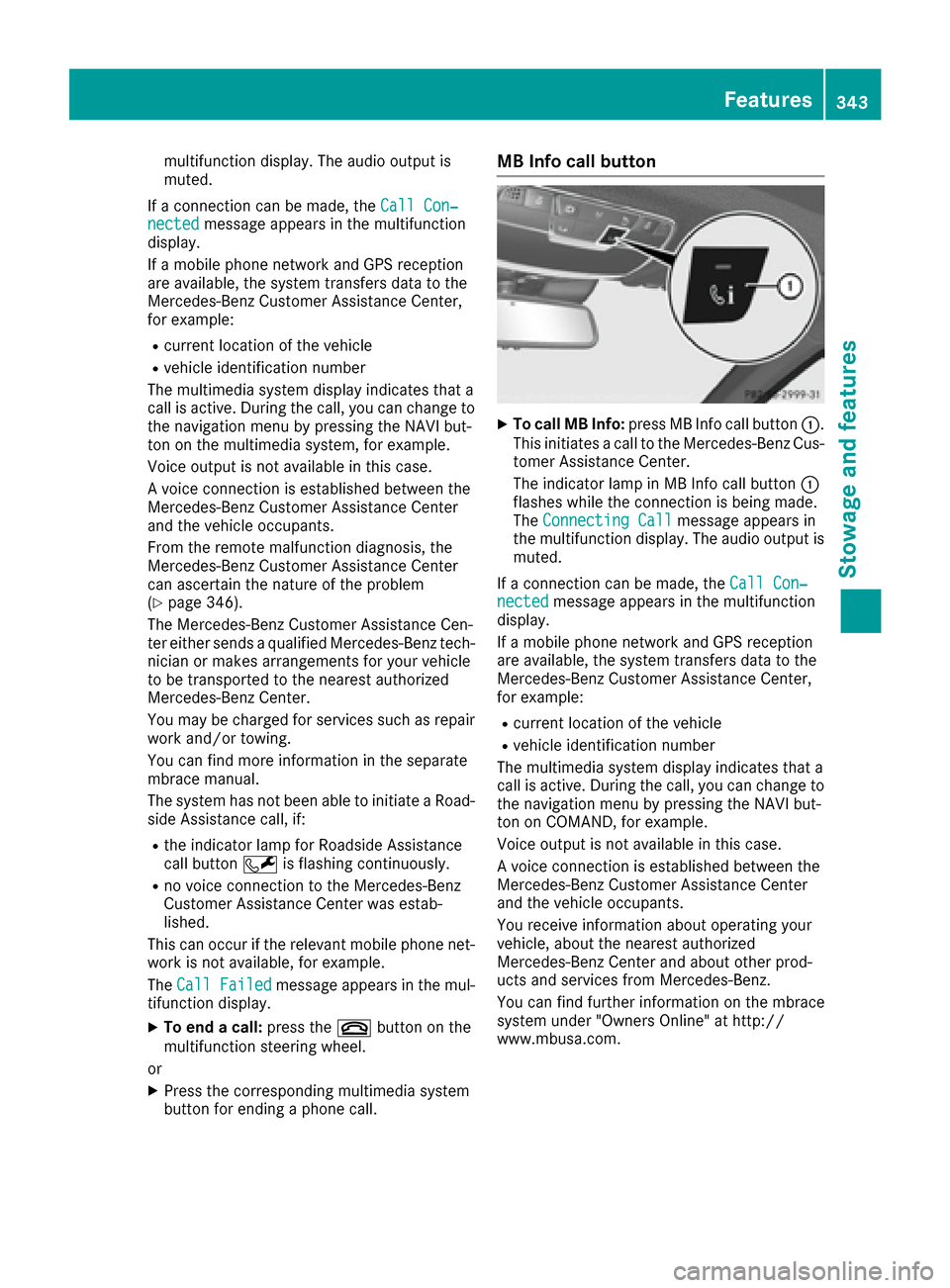
MB Info call button
XTo call MB Info: press MB Info call button :.
This initiates a call to the Mercedes-Benz Cus-
tomer Assistance Center.
The indicator lamp in MB Info call button :
flashes while the connection is being made.
The Connecting Call
message appears in
the multifunction display. The audio output is
muted.
If a connection can be made, the Call Con‐
nectedmessage appears in the multifunction
display.
If a mobile phone network and GPS reception
are available, the system transfers data to the
Mercedes-Benz Customer Assistance Center,
for example:
Rcurrent location of the vehicle
Rvehicle identification number
The multimedia system display indicates that a
call is active. During the call, you can change to
the navigation menu by pressing the NAVI but-
ton on COMAND, for example.
Voice output is not available in this case.
A voice connection is established between the
Mercedes-Benz Customer Assistance Center
and the vehicle occupants.
You receive information about operating your
vehicle, about the nearest authorized
Mercedes-Benz Center and about other prod-
ucts and services from Mercedes-Benz.
You can find further information on the mbrace
system under "Owners Online" at http://
www.mbusa.com.
Features343
Stowage and features
Z
Page 360 of 438
iThe ASSYST PLUS service interval display
does not show any information on the engine
oil level. Observe the notes on the engine oil
level (
Ypage 353).
The multifunction display shows a service mes-
sage for several seconds, e.g.:
RService A in XX Days
RService A Due
RService A Overdue by XX Days
Depending on the operating conditions of the
vehicle, the remaining time or distance until the
next service due date is displayed.
The letter A
orB, possibly in connection with a
number or another letter, indicates the type of
service. A
stands for a minor service and Bfor a
major service.
You can obtain further information from an
authorized Mercedes-Benz Center.
The ASSYST PLUS service interval display does
not take into account any periods of time during
which the battery is disconnected.
Maintaining the time-dependent service sched-
ule:
XNote down the service due date displayed in
the multifunction display before disconnect-
ing the battery.
or
XAfter reconnecting the battery, subtract the
battery disconnection periods from the ser-
vice date shown on the display.
Hiding a service message
XPress the aor% button on the steering
wheel.
Displaying service messages
XSwitch the ignition on.
XUse ò on the steering wheel to call up the
list of menus.
XPress 9or: on the steering wheel to
select the Servicemenu and confirm with
a.
XPress 9or: on the steering wheel to
select the ASSYST PLUSsubmenu and con-
firm with a.
The service due date appears in the multi-
function display.
Information about Service
Resetting the ASSYST PLUS service
interval display
!If the ASSYST PLUS service interval display
has been inadvertently reset, this setting can
be corrected at a qualified specialist work-
shop.
Have service work carried out as described in
the Maintenance Booklet. This may otherwise
lead to increased wear and damage to the
major assemblies or the vehicle.
A qualified specialist workshop, e.g. an author-
ized Mercedes-Benz Center, will reset the
ASSYST PLUS service interval display after the
service work has been carried out. You can also
obtain further information on maintenance
work, for example.
Special service requirements
The specified maintenance interval takes only
the normal operation of the vehicle into
account. Under arduous operating conditions or
increased load on the vehicle, maintenance
work must be carried out more frequently, for
example:
Rregular city driving with frequent intermediate
stops
Rif the vehicle is primarily used to travel short
distances
Ruse in mountainous terrain or on poor road
surfaces
Rif the engine is often left idling for long periods
Under these or similar conditions, have, for
example, the air filter, engine oil and oil filter
replaced or changed more frequently. Under
arduous operating conditions, the tires must be
checked more often. Further information can be obtained at a qualified specialist workshop, e.g.
an authorized Mercedes-Benz Center.
Driving abroad
An extensive Mercedes-Benz Service network is
also available in other countries. You can obtain
further information from any authorized
Mercedes-Benz Center.
358ASSYST PLUS
Maintenance and care
Page 367 of 438
become porous. As a result, plastic parts maycome loose in the event of air bag deploy-
ment. There is a risk of injury.
Do not use any care products and cleaning
agents to clean the cockpit.
!Do not affix the following to plastic surfaces:
Rstickers
Rfilms
Rscented oil bottles or similar items
You can otherwise damage the plastic.
!Do not allow cosmetics, insect repellent or
sunscreen to come into contact with the plas-
tic trim. This maintains the high-quality look of
the surfaces.
XWipe the plastic trim with a damp, lint-free
cloth, e.g. a microfiber cloth.
XHeavy soiling: use care and cleaning prod-
ucts recommended and approved by
Mercedes-Benz.
The surface may change color temporarily.
Wait until the surface is dry again.
Cleaning the steering wheel and gear or
selector lever
XThoroughly wipe with a damp cloth or use
leather care agents that have been recom-
mended and approved by Mercedes-Benz.
Cleaning genuine wood and trim ele-
ments
!Do not use solvent-based cleaning agents
such as tar remover, wheel cleaners, polishes
or waxes. There is otherwise a risk of damag- ing the surface.
!Do not use chrome polish on trim pieces.
The trim pieces have a chrome look but are
mostly made of anodized aluminum and can
lose their shine if chrome polish is used. Use
a damp, lint-free cloth instead when cleaning
the trim pieces.
If the chrome-plated trim pieces are very
dirty, you can use a chrome polish. If you are
unsure as to whether the trim pieces are
chrome-plated or not, consult an authorized
Mercedes-Benz Center.
XWipe the wooden trim and trim pieces with a
damp, lint-free cloth, e.g. a microfiber cloth.
XHeavy soiling: use care and cleaning prod-
ucts recommended and approved by
Mercedes-Benz.
Cleaning the seat covers
General notes
!Do not use a microfiber cloth to clean covers
made out of real leather, artificial leather or
DINAMICA. If used often, these can damage
the cover.
Note that regular care is essential to ensure that
the appearance and comfort of the covers is
retained over time.
Genuine leather seat covers
!To retain the natural appearance of the
leather, observe the following cleaning
instructions:
RClean genuine leather covers carefully with a damp cloth and then wipe the covers
down with a dry cloth.
RMake sure that the leather does not
become soaked. It may otherwise become
rough and cracked.
ROnly use leather care agents that have
been tested and approved by Mercedes-
Benz. You can obtain these from a qualified
specialist workshop.
Leather is a natural product.
It exhibits natural surface characteristics, for
example:
Rdifferences in the texture
Rmarks caused by growth and injury
Rslight nuances of color
These are characteristics of leather and not
material defects.
Seat covers of other materials
!Observe the following when cleaning:
Rclean artificial leather covers with a cloth
moistened with a solution containing 1%
detergent (e.g. dish washing liquid).
Rclean cloth covers with a microfiber cloth
moistened with a solution containing 1%
detergent (e.g. dish washing liquid). Rub
carefully and always wipe entire seat sec-
tions to avoid leaving visible lines. Leave
Care365
Maintenance and care
Z
Page 369 of 438
Useful information
i
This Operator's Manual describes all models
and all standard and optional equipment of
your vehicle available at the time of publica-
tion of the Operator's Manual. Country-spe-
cific differences are possible. Please note
that your vehicle may not be equipped with all
features described. This also applies to
safety-related systems and functions.
iRead the information on qualified specialist
workshops (Ypage 28).
Where will I find...?
Vehicle tool kit
General notes
The towing eye is located in the stowage well
under the trunk floor.
Some tools for changing a wheel are specific to
the vehicle. For more information on which tire
changing tools are required and approved to
perform a wheel change on your vehicle, consult a qualified specialist workshop.
Tools required for changing a wheel may
include, for example:
RJack
RWheel chock
RLug wrench
RRatchet wrench
RAlignment bolt
Vehicles with a TIREFIT kit
:Tire sealant filler bottle
;Tire inflation compressor
=Towing eye
XOpen the trunk lid.
XLift the trunk floor upwards (Ypage 329).
XUse the TIREFIT kit (Ypage 369).
Mercedes-AMG vehicles
:Tire sealant filler bottle
;Jack
=Ratchet
?Alignment bolt
AJacking support
BSocket
CLug wrench
DTowing eye
EFolding wheel chock
FTire inflation compressor
The tire-change tool kit is in a tray in the stowage
well under the trunk floor.
XOpen the trunk lid.
XLift the trunk floor upwards (Ypage 329).
iExample: equipment and country-specific
variations possible.
Flat tire
Preparing the vehicle
Your vehicle may be equipped with:
Rtires with run-flat characteristics
(MOExtended tires) (Ypage 368)
Vehicle preparation is not necessary on vehi-
cles with MOExtended tires
Ra TIREFIT kit (Ypage 367)
Vehicles equipped with MOExtended tires are
not equipped with a TIREFIT kit at the factory. It
is therefore recommended that you additionally
equip your vehicle with a TIREFIT kit if you mount
tires that do not feature run-flat properties, e.g.
Flat tire367
Breakdown assistance
Page 394 of 438

the information on display messages
(Ypage 306).
It may take up to ten minutes for a malfunction of the tire pressure monitor to be indicated. A
malfunction will be indicated by the tire pres-
sure warning lamp flashing for approximately
one minute and then remaining lit. When the
malfunction has been rectified, the tire pressure
warning lamp goes out after a few minutes of
driving.
The tire pressure values indicated by the on-
board computer may differ from those meas-
ured at a gas station with a pressure gauge. The
tire pressures shown by the on-board computer
refer to those measured at sea level. At high
altitudes, the tire pressure values indicated by a
pressure gauge are higher than those shown by the on-board computer. In this case, do not
reduce the tire pressures.
The operation of the tire pressure monitor can
be affected by interference from radio transmit-
ting equipment (e.g. radio headphones, two-way
radios) that may be being operated in or near the vehicle.
Checking the tire pressure electroni-
cally
XMake sure that the SmartKey is in position 2
in the ignition lock (Ypage 162).
XUse ò on the steering wheel to call up the
list of menus.
XPress 9or: on the steering wheel to
select the Servicemenu.
XPress theabutton.
XPress 9or: to select Tire Pres‐sure.
XPress the abutton.
The current tire pressure of each tire is shown
in the multifunction display.
If the vehicle was parked for longer than
20 minute s,the following message appears:
Tire
pressurewillbedisplayedafterdriving a few minutes.
After a teach-in process, the tire pressure mon- itor automatically detects new wheels or new
sensors. As long as a clear allocation of the tire
pressure value to the individual wheels is not
possible, the Tire
PressureMonitorActivemessage is shown instead of the tire pressure
display. The tire pressures are already being
monitored.
Tire pressure monitor warning mes-
sages
If the tire pressure monitor detects a pressure
loss in one or more tires, a warning message is
shown in the multifunction display. The yellow
tire pressure warning lamp then lights up.
RIf thePlease Correct Tire Pressuremessage appears in the multifunction display,
the tire pressure in at least one tire is too low.
The tire pressure must be corrected when the
opportunity arises.
RIf theCheck Tiresmessage appears in the
multifunction display, the tire pressure in at
least one tire has dropped significantly. The
tires must be checked.
RIf the WarningTireMalfunctionmessage
appears in the multifunction display, the tire
pressure in at least one tire has dropped sud-
denly. The tires must be checked.
Observe the instructions and safety notes in the
display messages in the "Tires" section
(
Ypage 306).
If the wheel positions on the vehicle are rotated,
the tire pressures may be displayed for the
wrong positions for a short time. This is rectified after a few minutes of driving, and the tire pres-
sures are displayed for the correct positions.
Restarting the tire pressure monitor
When you restart the tire pressure monitor, all
existing warning messages are deleted and the
warning lamps go out. The monitor uses the cur- rently set tire pressures as the reference values
for monitoring. In most cases, the tire pressure
monitor will automatically detect the new refer-
ence values after you have changed the tire
pressure. However, you can also define refer-
ence values manually as described here. The tire
pressure monitor then monitors the new tire
pressure values.
XSet the tire pressure to the value recommen- ded for the corresponding driving situation on
the Tire and Loading Information placard on
the driver's side B-pillar (
Ypage 387).
You can find more tire pressure values for
various operating conditions in the tire pres-
sure table inside the fuel filler flap
(
Ypage 387).
XMake sure that the tire pressure is correct on
all four wheels.
392Tire pressure
Wheels and tires