2016 MERCEDES-BENZ S-Class SEDAN tail light
[x] Cancel search: tail lightPage 7 of 438

Brake Assistsee BAS (Brake Assist System)
Brake fluid
Display message ............................ 283
Notes ............................................. 430
Brake force distribution
see EBD (electronic brake force
distribution)
Brake lamps
Display message ............................ 291
Brake pedal
Pedal resistance/pedal travel .......... 44
Brakes
ABS .................................................. 68
Adaptive Brake Assist ...................... 72
BAS .................................................. 69
BAS PLUS with Cross-Traffic
Assist ............................................... 69
Brake fluid (notes) ......................... 430
Display message ............................ 278
EBD .................................................. 75
High-performance brake system .... 196
Hill start assist ............................... 165
HOLD function ............................... 208
Important safety notes .................. 194
Maintenance .................................. 195
Parking brake ................................ 190
RBS warning lamp .......................... 315
Recuperative Brake System ............. 44
Riding tips ...................................... 194
Warning lamp ................................. 315
Breakdown
Where will I find...? ........................ 367
see Flat tire
see Towing away
Brightness control (instrument
cluster lighting) ................................... 35
Buttons on the steering wheel ......... 257
C
California
Important notice for retail cus-
tomers and lessees .......................... 25
Calling up a malfunction
see Display messages
Camera
see 360° camera see Rear view camera
Car
see Vehicle
Care
360° camera ................................. 363
Car wash ........................................ 359
Carpets .......................................... 366
Display ........................................... 364
Exhaust pipe .................................. 363
Exterior lights ................................ 362
Gear or selector lever .................... 365
General notes ................................ 359
Interior ........................................... 364
Matte finish ................................... 361
Night View Assist Plus ................... 364
Paint .............................................. 361
Plastic trim .................................... 364
Power washer ................................ 360
Rear view camera .......................... 363
Roof lining ...................................... 366
Seat belt ........................................ 366
Seat cover ..................................... 365
Sensors ......................................... 362
Steering wheel ............................... 365
Trim pieces .................................... 365
Washing by hand ........................... 360
Wheels ........................................... 361
Windows ........................................ 362
Wiper blades .................................. 362
Wooden trim .................................. 365
CD player (on-board computer) ........ 266
Center console
Overview .......................................... 37
Stowage space .............................. 326
Center console in the rear com-
partment
Stowage compartment .................. 327
Central locking
Locking/unlocking (SmartKey) ........ 79
Changing the media source ............. 265
Charging
see Charging the high-voltage bat-
tery (important safety notes)
Charging cable
Connecting .................................... 185
Controls ......................................... 183
Important safety notes .................. 183
Indicator lamp ................................ 184
Index5
Page 21 of 438

Switching on/off ........................... 131
Start/Stop button
General notes ................................ 162
Key positions ................................. 163
Removing ....................................... 163
Starting the engine ........................ 164
Start/stop function
see ECO start/stop function
Starting (engine) ................................ 164
STEER CONTROL .................................. 77
Steering
Display message ............................ 311
Warning lamps ............................... 324
Steering Assist
see DISTRONIC PLUS
Steering Assist and Stop&Go Pilot
(DISTRONIC PLUS)
Display message ............................ 305
Steering assistant STEER CON-
TROL
see STEER CONTROL
Steering wheel
Adjusting (electrically) ................... 120
Button overview ............................... 35
Buttons (on-board computer) ......... 257
Cleaning ......................................... 365
EASY ENTRY/EXIT feature ............. 122
Important safety notes .................. 120
Paddle shifters ............................... 174
Steering wheel heating .................. 120
Storing settings (memory func-
tion) ............................................... 126
Steering wheel heating
Problem (malfunction) ................... 122
Switching on/off ........................... 120
Steering wheel paddle shifters ........ 174
Stop&Go Pilot
see DISTRONIC PLUS
Stowage areas ................................... 325
Stowage compartments
Armrest (under) ............................. 327
Center console .............................. 326
Center console in rear compart-
ment .............................................. 327
Cup holders ................................... 330
Door ............................................... 327
Eyeglasses compartment ............... 326
Glove box ....................................... 326 Important safety information ......... 325
Rear ............................................... 327
Rear seat backrest ......................... 328
Stowage net ................................... 329
see Stowage areas
Stowage net ....................................... 329
Stowage space
Folding table .................................. 328
Parcel net retainers ....................... 329
Securing a load .............................. 329
Stowage well beneath the trunk
floor .................................................... 329
Summer tires
In w
inter ........................................ 386
Sun visor ............................................ 333
Suspension mode
Active Body Control ABC ............... 210
Suspension setting
AIRMATIC ...................................... 212
Suspension settings
SETUP (on-board computer) .......... 276
Switching air-recirculation mode
on/off ................................................. 152
T
Tachometer ........................................ 256
Tail lamps
Display message ............................ 292
see Lights
Tank content
Fuel gauge ....................................... 33
Technical data
Capacities ...................................... 427
Information .................................... 425
Tires/wheels ................................. 410
Vehicle data ................................... 433
Telephone
Accepting a call (multifunction
steering wheel) .............................. 267
Display message ............................ 311
Introduction ................................... 267
Menu (on-board computer) ............ 267
Number from the phone book ........ 268
Redialing ........................................ 268
Rejecting/ending a call ................. 268
Temperature
Coolant .......................................... 257
Index19
Page 32 of 438

These data memories temporarily or perma-
nently store technical information about:
Rvehicle's operating state
Rincidents
Rmalfunctions
In general, this technical information docu-
ments the state of a component, a module, a
system or the surroundings.
These include, for example:
Roperating conditions of system components,
e.g. fluid levels
Rthe vehicle's status messages and those of its
individual components, e.g. number of wheel
revolutions/speed, deceleration in move-
ment, lateral acceleration, accelerator pedal
position
Rmalfunctions and defects in important system
components, e.g. lights, brakes
Rvehicle reactions and operating conditions in
special driving situations, e.g. air bag deploy-
ment, intervention of stability control sys-
tems
Rambient conditions, e.g. outside temperature
This data is of an exclusively technical nature
and can be used to:
Rassist in recognizing and rectifying malfunc-
tions and defects
Ranalyze vehicle functions, e.g. after an acci-
dent
Roptimize vehicle function
The data cannot be used to trace the vehicle's
movements.
When your vehicle is serviced, technical infor-
mation can be read from the event data memory
and malfunction data memory.
Services include, for example:
Rrepair services
Rservice processes
Rwarranties
Rquality assurance
The vehicle is read out by employees of the ser-
vice network (including the manufacturer) using
special diagnostic testers. More detailed infor-
mation is obtained from it, if required.
After a malfunction has been rectified, the infor-
mation is deleted from the malfunction memory or is continually overwritten.
When operating the vehicle, situations are con-
ceivable in which this technical data, in connec- tion with other information (if necessary, under
consultation with an authorized expert), could
be traced to a person.
Examples include:
Raccident reports
Rdamage to the vehicle
Rwitness statements
Further additional functions that have been con-
tractually agreed upon with the customer allow
certain vehicle data to be conveyed by the vehi-
cle as well. The additional functions include, for
example, vehicle location in case of an emer-
gency.
COMAND/mbrace
If the vehicle is equipped with COMAND or
mbrace, additional data about the vehicle's
operation, the use of the vehicle in certain sit-
uations, and the location of the vehicle may be
compiled through COMAND or the mbrace sys-
tem.
For additional information please refer to the
COMAND User Manual or the Digital Operator's
Manual and/or the mbrace Terms and Condi-
tions.
Event data recorders
This vehicle is equipped with an event data
recorder (EDR). This vehicle is equipped with an
event data recorder (EDR). The main purpose of
an EDR is to record, in certain crash or near
crash-like situations, such as an air bag deploy-
ment or hitting a road obstacle, data that will
assist in understanding how a vehicle's systems
performed. The EDR is designed to record data
related to vehicle dynamics and safety systems for a short period of time, typically 30 seconds
or less.
The EDR in this vehicle is designed to record
such data as:
RHow various systems in your vehicle were
operating
RWhether or not the driver and passenger
safety belts were buckled/fastened
RHow far (if at all) the driver was depressing theaccelerator and/or brake pedal and
RHow fast the vehicle was traveling.
30Introduction
Page 47 of 438

Information on restraint system operation can
be found under "Triggering of the Emergency
Tensioning Devices and air bags" (
Ypage 57).
For information on children traveling with you in
the vehicle and on child restraint systems, see
"Children in the vehicle" (
Ypage 61).
Important safety notes
GWARNING
Modifications to the restraint system may
cause it to no longer work as intended. The
restraint system may then not perform its
intended protective function and may fail in an
accident or trigger unexpectedly, for example.
This poses an increased risk of injury or even fatal injury.
Never modify parts of the restraint system.
Never tamper with the wiring, the electronic
components or their software.
If it is necessary to modify an air bag system to
accommodate a person with disabilities, con-
tact an authorized Mercedes-Benz Center for
details. USA only: for further information con-
tact our Customer Assistance Center at
1-800-FOR-MERCedes (1‑800‑367‑6372).
Restraint system warning lamp
The functions of the restraint system are
checked after the ignition is switched on and at regular intervals while the engine is running.
Therefore, malfunctions can be detected in
good time.
The 6 restraint system warning lamp in the
instrument cluster lights up when the ignition is
switched on. It goes out no later than a few sec- onds after the vehicle is started. The compo-
nents of the restraint system are in operational
readiness.
A malfunction has occurred if the 6restraint
system warning lamp:
Rdoes not light up after the ignition is switched
on
Rdoes not go out after a few seconds with the
engine running
Rlights up again while the engine is running
All vehicles, except hybrid vehicles:
GWARNING
If restraint system is malfunctioning, restraint
system components may be triggered unin-
tentionally or might not be triggered at all in
the event of an accident with a high rate of
vehicle deceleration. This can affect the Emer- gency Tensioning Device or air bag, for exam-
ple. This poses an increased risk of injury or
even fatal injury.
Have the restraint system checked and
repaired in a qualified specialist workshop as
soon as possible.
Hybrid vehicles:
GDANGER
If the restraint system is malfunctioning, indi- vidual restraint system components may be
triggered unintentionally or might not be trig-
gered at all in the event of an accident with a
high rate of vehicle deceleration. This could
affect Emergency Tensioning Devices or air
bags, for example. The vehicle's high-voltage
electrical system may also not be deactivated
as intended in the event of an accident. You
could suffer an electric shock if you touch the
damaged components of the vehicle's high-
voltage electrical system. This poses an
increased risk of injury or even fatal injury.
Have the restraint system checked and
repaired immediately at a qualified specialist
workshop. Immediately switch off the ignition
and remove the SmartKey from the ignition
lock after an accident.
Occupant safety45
Safety
Z
Page 185 of 438

Switch on the building protection system again
after it has been triggered. Otherwise, the
charging process cannot be continued.
General information about the charging
procedure
Pay attention to the "Important safety notes"
(Ypage 180).
The vehicle socket is located in the rear bumper on the right below the tail lamp.
The charge socket flap and the vehicle are cen-
trally locked or unlocked simultaneously.
Charging the high-voltage battery via
the electrical outlet
Charging cable for electrical outlets
Important safety notes
!Only use the charging cable to charge the
high-voltage battery. Do not use the charging
cable for other purposes. It may otherwise be damaged.
The vehicle is supplied with a country-specific
charging cable for connection to a mains socket.
Only use the charging cable supplied with the
vehicle or a charging cable approved for the
vehicle.
iIf you use the supplied 12 A charging cable
to charge a high-voltage battery:
Rthe charge time increases considerably
Relectrical consumption increases consider-
ably
Where possible, charge the high-voltage bat-
tery at a charging station (
Ypage 186). Only
then can certified electrical energy consump-
tion levels be reached.
iThe charging process can vary depending on
the power supply. Therefore, always observe
the local information.
Information about charging from a wallbox can
be found at (
Ypage 185).
Information about charging at a charging station
can be found at (
Ypage 186).
Stowing the charging cable
The charging cable can be stowed and held in
place in the bag provided in the trunk of the
vehicle.
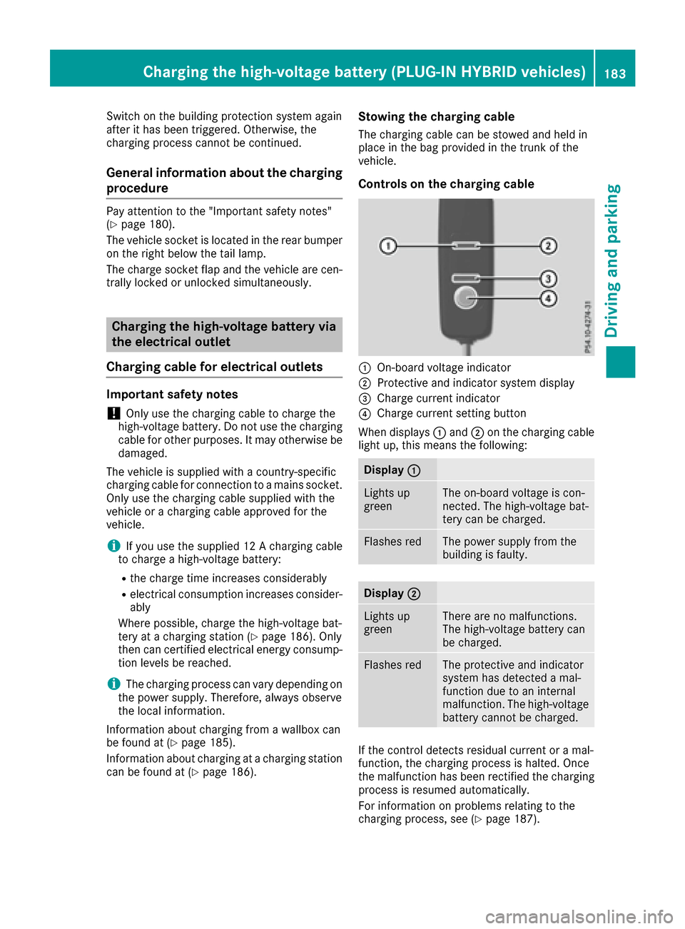
Controls on the charging cable
:On-board voltage indicator
;Protective and indicator system display
=Charge current indicator
?Charge current setting button
When displays :and ;on the charging cable
light up, this means the following:
Display :
Lights up
greenThe on-board voltage is con-
nected. The high-voltage bat-
tery can be charged.
Flashes redThe power supply from the
building is faulty.
Display;
Lights up
greenThere are no malfunctions.
The high-voltage battery can
be charged.
Flashes redThe protective and indicator
system has detected a mal-
function due to an internal
malfunction. The high-voltage
battery cannot be charged.
If the control detects residual current or a mal-
function, the charging process is halted. Once
the malfunction has been rectified the charging
process is resumed automatically.
For information on problems relating to the
charging process, see (
Ypage 187).
Charging the high-voltage battery (PLUG-IN HYBRID vehicles)183
Driving and parking
Z
Page 294 of 438

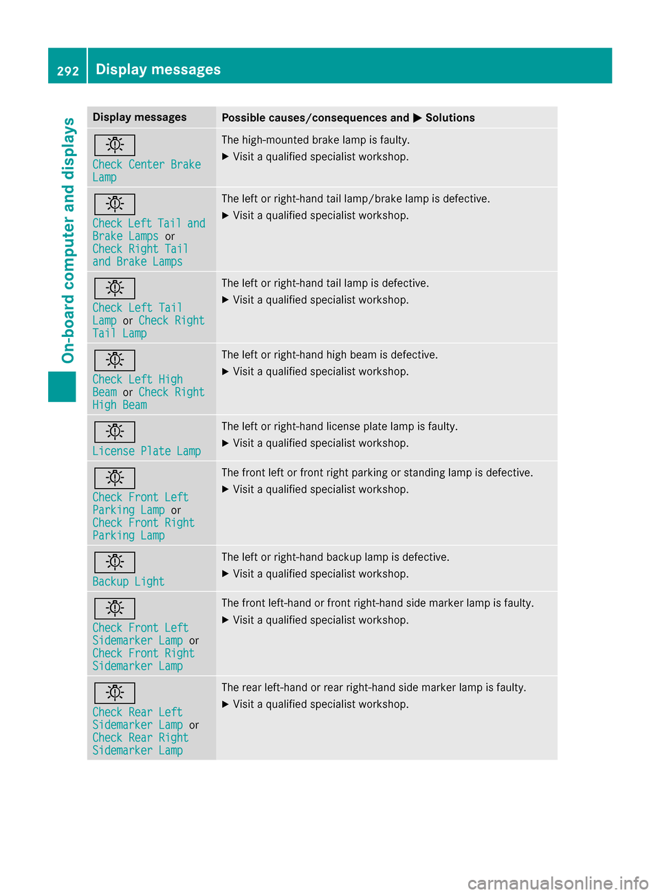
Display messagesPossible causes/consequences andMSolutions
b
Check Center BrakeLamp
The high-mounte dbrak elamp is faulty.
XVisit aqualified specialist workshop .
b
CheckLeftTailandBrake Lampsor
Check Right Tai l
and Brake Lamps
The leftor right-hand tai llamp/brake lamp is defective.
XVisit aqualified specialist workshop .
b
Check LeftTai lLamporCheck RightTai lLam p
The lef tor right-hand tai llamp is defective.
XVisit aqualified specialist workshop .
b
Check LeftHig hBeamorCheck RightHig hBea m
The lef tor right-hand high beam is defective.
XVisit aqualified specialist workshop .
b
LicensePlate Lam p
The leftor right-hand license plat elamp is faulty.
XVisit aqualified specialist workshop .
b
Check Front LeftParkingLam por
Check Front Right
Parkin gLam p
The fron tlef tor fron tright parking or standing lamp is defective.
XVisit aqualified specialist workshop .
b
Backup Light
The leftor right-hand backup lamp is defective.
XVisit aqualified specialist workshop .
b
Check Front LeftSidemarkerLam por
Check Front Right
Sidemarke rLam p
The fron tleft-han dor fron tright-hand side marke rlamp is faulty.
XVisit aqualified specialist workshop .
b
Check RearLef tSidemarke rLam por
Check Rea rRight
Sidemarke rLam p
The rear left-han dor rear right-hand side marke rlamp is faulty.
XVisit aqualified specialist workshop .
292Display messages
On-board computer and displays
Page 404 of 438

required speed rating for your vehicle can be
found in the "Tires" section (Ypage 410).
Further information about reading tire data can
be obtained from any qualified specialist work-
shop.
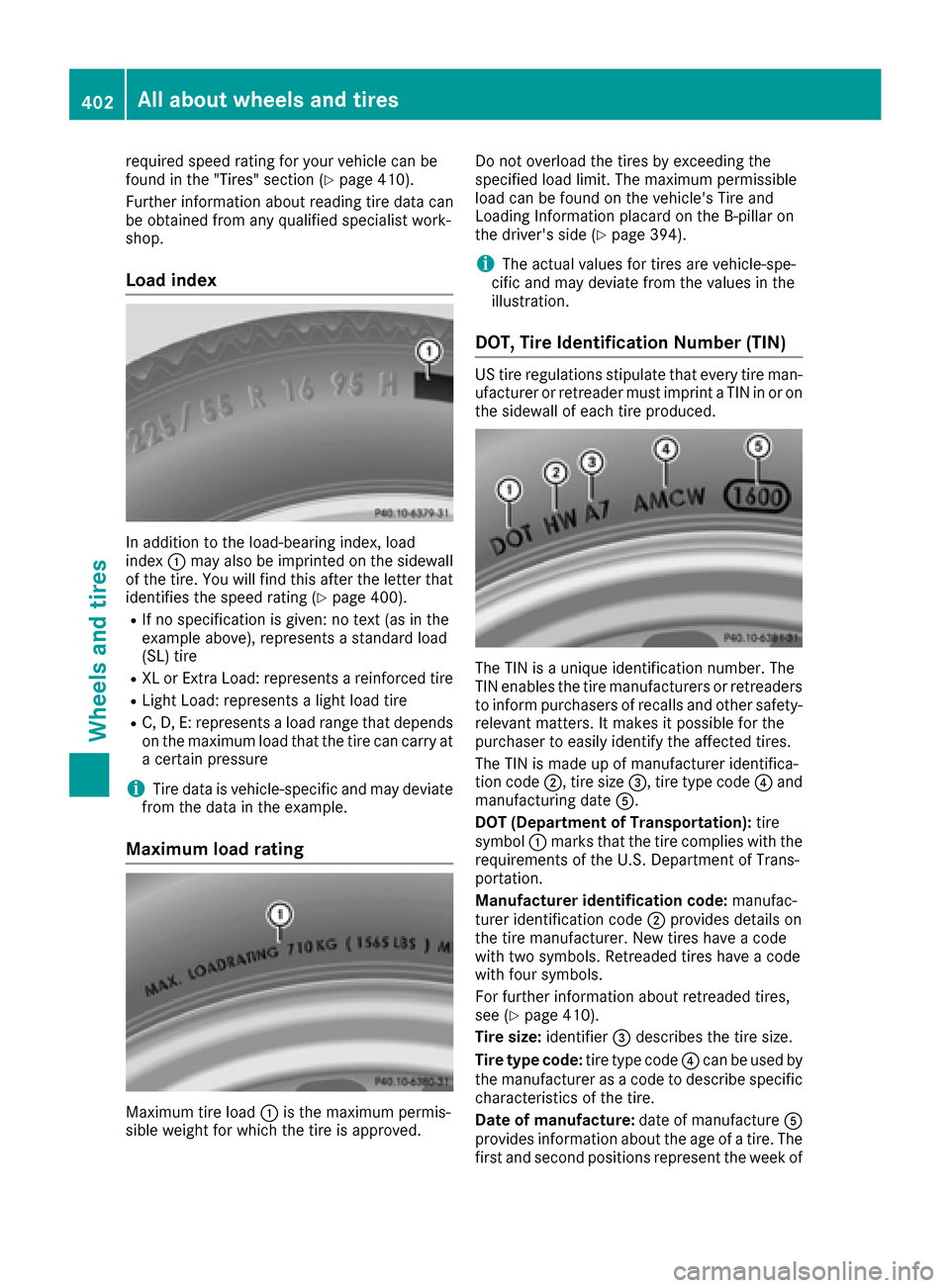
Load index
In addition to the load-bearing index, load
index :may also be imprinted on the sidewall
of the tire. You will find this after the letter that
identifies the speed rating (
Ypage 400).
RIf no specification is given: no text (as in the
example above), represents a standard load
(SL) tire
RXL or Extra Load: represents a reinforced tire
RLight Load: represents a light load tire
RC, D, E: represents a load range that depends
on the maximum load that the tire can carry at
a certain pressure
iTire data is vehicle-specific and may deviate
from the data in the example.
Maximum load rating
Maximum tire load :is the maximum permis-
sible weight for which the tire is approved. Do not overload the tires by exceeding the
specified load limit. The maximum permissible
load can be found on the vehicle's Tire and
Loading Information placard on the B-pillar on
the driver's side (
Ypage 394).
iThe actual values for tires are vehicle-spe-
cific and may deviate from the values in the
illustration.
DOT, Tire Identification Number (TIN)
US tire regulations stipulate that every tire man-
ufacturer or retreader must imprint a TIN in or on
the sidewall of each tire produced.
The TIN is a unique identification number. The
TIN enables the tire manufacturers or retreaders
to inform purchasers of recalls and other safety-
relevant matters. It makes it possible for the
purchaser to easily identify the affected tires.
The TIN is made up of manufacturer identifica-
tion code ;, tire size =, tire type code ?and
manufacturing date A.
DOT (Department of Transportation): tire
symbol :marks that the tire complies with the
requirements of the U.S. Department of Trans-
portation.
Manufacturer identification code: manufac-
turer identification code ;provides details on
the tire manufacturer. New tires have a code
with two symbols. Retreaded tires have a code
with four symbols.
For further information about retreaded tires,
see (
Ypage 410).
Tire size: identifier=describes the tire size.
Tire type code: tire type code?can be used by
the manufacturer as a code to describe specific
characteristics of the tire.
Date of manufacture: date of manufactureA
provides information about the age of a tire. The
first and second positions represent the week of
402All about wheels and tires
Wheels and tires