2016 MERCEDES-BENZ GLC COUPE light
[x] Cancel search: lightPage 221 of 389
If you drive at speeds above 60 km/h and lane
markings are detected, the lines on the assis- tant display (Y page 239) appear in green.
Active Lane Keeping Assist is ready for use.
X To deactivate: press button;.
Indicator lamp :goes out. Active Lane Keep-
ing Assist is deactivated. The Lane
Lane Keeping
Keeping
Assist off
Assist off message appears on the multi-
function display.
Selecting Standard or Adaptive setting X On the Assistance
Assistance menu on the on-board
computer, select the Active Lane Keep‐
Active Lane Keep‐
ing Assist
ing Assist function (Ypage 242).
X Select setting Standard
StandardorAdaptive
Adaptive.
When Standard
Standard is selected, no warning vibra-
tion occurs if:
R you have switched on the turn signal. In this
event, the warnings are suppressed for a
certain period of time
R a driving safety system such as ABS, BAS or
ESP ®
engages
When Adaptive Adaptive is selected, no warning vibra-
tion occurs if:
R you have switched on the turn signal. In this
event, the warnings are suppressed for a
certain period of time
R a driving safety system such as ABS, BAS or
ESP ®
engages
R you accelerate hard, e.g. kickdown
R you brake hard
R you steer actively, e.g. swerve to avoid an
obstacle or change lane quickly
R you cut the corner on a sharp bend
To ensure that you are warned only when nec-
essary and in good time if you cross the lane
marking, the system detects certain conditions
and warns you accordingly.
The warning vibration occurs earlier in the fol-
lowing situations:
R you approach the outer lane marking on a
bend
R the road has very wide lanes, e.g. a motorway
R the system detects solid lane markings
The warning vibration occurs later in the follow- ing situations:
R the road has narrow lanes
R you cut the corner on a bend Towing a trailer
If you couple up a trailer, make sure that you
have correctly established the electrical con-
nection. This can be accomplished by checking
the trailer lighting. Towing a trailer
Important safety notes
G
WARNING
You could lose control of the vehicle/trailer
combination if it begins to swerve. The vehi-
cle/trailer combination could even overturn.
There is a risk of an accident.
On no account should you attempt to
straighten out the vehicle/trailer combina-
tion by increasing speed. Decrease your
speed and do not countersteer. Brake if nec-
essary. G
WARNING
If the maximum permissible load for a carrier system is exceeded, the carrier could come
loose from the vehicle and endanger other
road users. There is a risk of an accident and injury.
Never exceed the maximum permissible load
when using a carrier.
! If you have a trailer tow hitch retrofitted,
changes to the engine cooling system may be necessary, depending on the vehicle type.
If you have a trailer tow hitch retrofitted,
observe the anchorage points on the chassis.
Retrofitting a trailer tow hitch is only permissible
if a trailer load is specified in your vehicle docu-
ments. If this is not the case, then the vehicle is not approved for towing a trailer.
For more information, please contact a qualifiedspecialist workshop.
Exceeding the maximum permissible nose-
weight of the trailer drawbar on the ball coupling
may cause damage.
Damage may be caused to the following:
R towing vehicle
R trailer 218
Towing a trailerDriving and parking
Page 225 of 389
Coupling up a trailer
X Apply the electric parking brake manually.
X Shift the transmission to position P.
X Position the trailer on a level surface behind
the vehicle.
X Couple up the trailer.
X Establish the electrical connection between
the vehicle and the trailer.
X Check that the trailer lighting system is work-
ing.
X Push the combination switch upwards and
downwards and check whether the corre-
sponding turn signal indicator on the trailer is
flashing.
A connected trailer is only detected when the
electrical connection is established correctly
and the lighting system is working properly. The
function of other systems also depends on this, for example:
R ESP ®
R PARKTRONIC
R Active Parking Assist
R Active Blind Spot Assist
R Active Lane Keeping Assist Uncoupling a trailer
G
WARNING
If you uncouple a trailer with an engaged over- run brake, you could trap your hand between
the vehicle and the trailer drawbar. This poses a risk of injury.
Do not uncouple a trailer with an engaged
overrun brake. G
WARNING
Vehicles with level control:
If you disconnect the trailer cable, the vehicle is lowered. This can cause you or others to
become trapped between the vehicle body
and tyres, or underneath the vehicle. This
poses a risk of injury.
Make sure that no-one is in the immediate
vicinity of the wheel arch or underneath the
vehicle when disconnecting the trailer cable. !
Do not disconnect a trailer with an engaged
overrun brake. Otherwise, your vehicle could
be damaged by the rebounding of the overrun
brake.
! Remove the adapter cable before folding in
the ball coupling. You could otherwise dam-
age the rear bumper and the adapter cable.
X Apply the electric parking brake manually.
X Shift the transmission to position P.
X Switch off the engine.
X Secure the vehicle and trailer against rolling
away.
X Remove the trailer cable and uncouple the
trailer. Trailer power supply
! Accessories with a maximum power con-
sumption of 180 W can be connected to the
permanent power supply.
The trailer battery may not be charged from
the power supply.
When it leaves the factory, your vehicle's trailer
socket is equipped with a permanent power
supply and a power supply that is switched on
via the ignition lock.
The permanent power supply is supplied via
trailer socket pin 9.
The power supply that is switched on via the
ignition lock is supplied via trailer socket pin 10.
The trailer's permanent power supply is
switched off in the event of low on-board voltage
and after six hours at the latest.
You can find more information about installing
the trailer electrics at a qualified specialist work- shop.
To activate the switched power supply:
X Turn the key to position 2in the ignition lock
(Y page 144).
or
X Press the Start/Stop button twice on vehicles
with KEYLESS-GO or the KEYLESS-GO start
function (Y page 144).222
Towing a trailerDriving and parking
Page 226 of 389
To deactivate the switched power supply:
X Turn the key to position 0in the ignition lock
(Y page 144).
or
X Press the Start/Stop button once on vehicles
with KEYLESS-GO or the KEYLESS-GO start
function (Y page 144). Failure check for LEDs
If LED lamps are fitted in the trailer, a malfunc-
tion message may appear in the multifunction
display even if there is no fault. The reason for
the error message may be that the current has
fallen below the minimum of 50 mA.
To ensure reliable operation of the failure indi-
cator, each LED chain in the trailer lighting must
be guaranteed a minimum current of 50 mA. Trailer with 7-pin connector
General notes Trailer with 7-pin connector:
you can connect
to the 13-pin socket on the ball coupling using
an adapter or, if necessary, an adapter cable.
Both can be obtained at a qualified specialist
workshop. Fitting the adapter !
Make sure that there is sufficient cable play
so that the cable cannot become detached
when cornering.
! Remove the adapter cable before folding in
the ball coupling. You could otherwise dam-
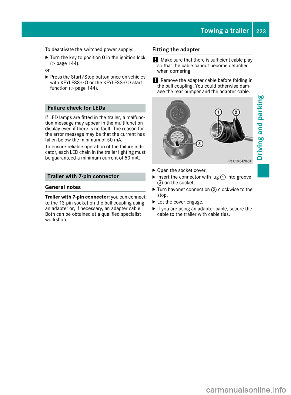
age the rear bumper and the adapter cable. X
Open the socket cover.
X Insert the connector with lug :into groove
= on the socket.
X Turn bayonet connection ;clockwise to the
stop.
X Let the cover engage.
X If you are using an adapter cable, secure the
cable to the trailer with cable ties. Towing a trailer
223Driving and parking Z
Page 231 of 389
Important safety notes
G
WARNING
Operating the integrated information systems and communications equipment in the vehicle
while driving will distract you from traffic con-
ditions. You could then lose control of the
vehicle. There is a risk of an accident.
Only operate these devices if road traffic con-
ditions permit. If you are unsure about the
surrounding conditions, pull over to a safe
location and make entries only while the vehi-
cle is stationary.
You must observe the legal requirements for the country in which you are currently driving whenoperating the on-board computer. G
WARNING
If the instrument cluster has failed or mal-
functioned, you may not recognise function
restrictions relevant to safety. The operating
safety of your vehicle may be impaired. There is a risk of an accident.
Drive on carefully. Have the vehicle checked
at a qualified specialist workshop immedi-
ately.
If the operating safety of your vehicle is
impaired, park the vehicle safely as soon as pos- sible. Contact a qualified specialist workshop.
The on-board computer shows only messages or warnings from certain systems on the multi-
function display. You should therefore make
sure your vehicle is operating safely at all times.
For an overview, see the instrument cluster illus-
tration (Y page 34).
HYBRID vehicles: make sure that you read the
separate Owner's Manual. Otherwise, you may
fail to recognise dangers. Displays and operation
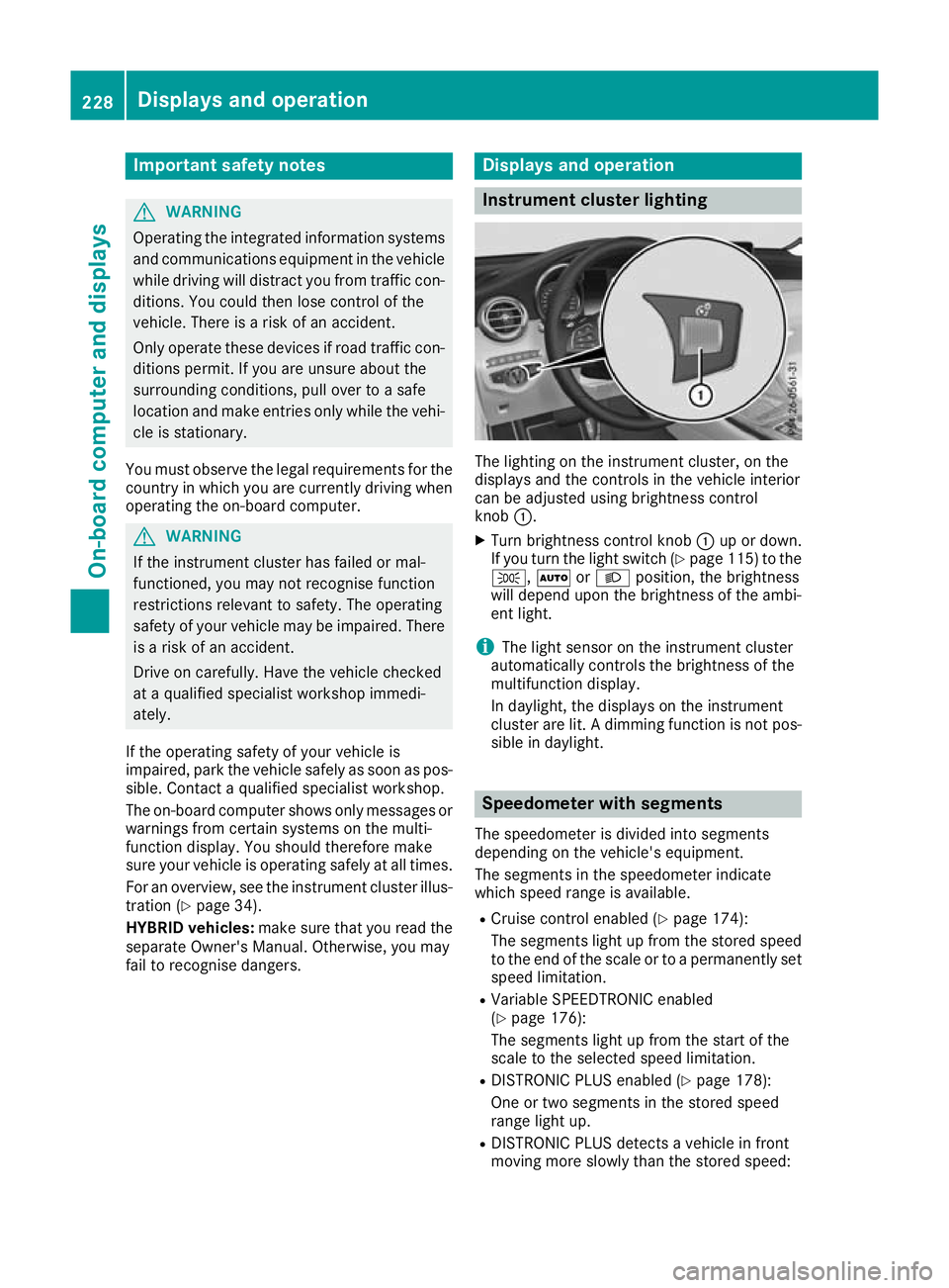
Instrument cluster lighting
The lighting on the instrument cluster, on the
displays and the controls in the vehicle interior
can be adjusted using brightness control
knob :.
X Turn brightness control knob :up or down.
If you turn the light switch (Y page 115) to the
T, ÃorL position, the brightness
will depend upon the brightness of the ambi-
ent light.
i The light sensor on the instrument cluster
automatically controls the brightness of the
multifunction display.
In daylight, the displays on the instrument
cluster are lit. A dimming function is not pos-
sible in daylight. Speedometer with segments
The speedometer is divided into segments
depending on the vehicle's equipment.
The segments in the speedometer indicate
which speed range is available.
R Cruise control enabled (Y page 174):
The segments light up from the stored speed to the end of the scale or to a permanently set
speed limitation.
R Variable SPEEDTRONIC enabled
(Y page 176):
The segments light up from the start of the
scale to the selected speed limitation.
R DISTRONIC PLUS enabled (Y page 178):
One or two segments in the stored speed
range light up.
R DISTRONIC PLUS detects a vehicle in front
moving more slowly than the stored speed: 228
Displays and operationOn-board computer and displays
Page 232 of 389
The segments between the speed of the vehi-
cle in front and the stored speed light up. Rev counter
! Do not drive in the overrevving range. Doing
so will damage the engine.
The red band in the rev counter indicates the
engine's overrevving range.
The fuel supply is interrupted to protect the
engine when the red band is reached. Outside temperature display
You should pay special attention to road condi-
tions when temperatures are around freezing
point.
Bear in mind that the outside temperature dis-
play indicates the measured air temperature
and not the road surface temperature.
The outside temperature display is in the multi-
function display (Y page 230).
Changes in the outside temperature are dis-
played after a short delay. Coolant temperature gauge
G
WARNING
If you open the bonnet while the engine is
overheating or while there is a fire in the
engine compartment, you could come into
contact with hot gases or other leaking ser-
vice products. There is a danger of injury.
Allow an overheating engine to cool down
before opening the bonnet. If there is a fire in the engine compartment, leave the bonnet
closed and notify the fire brigade.
The coolant temperature gauge is in the lower
section of the rev counter (Y page 34).
At high outside temperatures and when driving
in mountainous terrain, the coolant temperature
may rise to the end of the scale.
Under normal operating conditions and with the correct coolant level, the coolant temperature
may rise to 120 †. Operating the on-board computer
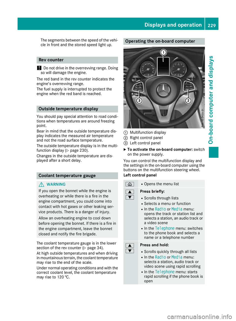
:
Multifunction display
; Right control panel
= Left control panel
X To activate the on-board computer: switch
on the power supply.
You can control the multifunction display and
the settings in the on-board computer using the buttons on the multifunction steering wheel.
Left control panel ò R
Opens the menu list 9
: Press briefly:
R Scrolls through lists
R Selects a menu or function
R In the Radio Radio orMedia
Media menu:
opens the track or station list and
selects a station, an audio track or a video scene
R In the Telephone Telephone menu: switches
to the phone book and selects a
name or a telephone number 9
: Press and hold:
R
Scrolls quickly through all lists
R In the Radio Radio orMedia
Media menu:
selects a station, audio track or
video scene using rapid scrolling
R In the Telephone Telephone menu: starts
rapid scrolling if the phone book is open Displays and operation
229On-board computer and displays Z
Page 234 of 389
R
È SPEEDTRONIC (Y page 176)
R ¯ Cruise control (Y page 174)
R a DISTRONIC PLUS Steering Assist and
Stop&Go Pilot (Y page 184)
R _ Adaptive Highbeam Assist
(Y page 119)
R _ Adaptive Highbeam Assist Plus
(Y page 119)
R è ECO start/stop function (Y page 148)
R ë HOLD function (Y page 186)
R ð Maximum permissible speed exceeded
(for certain countries only) Head-up display
General notes The Head-up Display projects information from
the navigation system and the driver assistance
systems above the dashboard into the driver's
field of vision. This way, the Head-up Display
enables drivers to see information without hav-
ing to take their eyes off the road.
A requirement for the display of the content is
that the following functions are available in the
vehicle and are switched on:
R Cruise control
R SPEEDTRONIC
R DISTRONIC PLUS
R Traffic Sign Assist
R Navigation
Important safety notes The head-up display is only an aid and is not a
substitute for attentive driving.
Speed limits and overtaking restrictions are not
always correctly displayed. Traffic signs always
have priority over the Traffic Sign Assist display.
The visibility of the head-up display is influenced by the following conditions:
R the driver's seat position
R the positioning of the display image
R the general light conditions
R sunglasses with polarisation filters
R wet road surfaces
R blocking of sunlight by objects on the display
cover In the event of extreme sunlight, sections of the
display may fade. This can be reversed by
switching the head-up display off and on again.
i Vehicles with the head-up display are equip-
ped with a special windscreen. Should repairs
be necessary, have the windscreen replaced
at a qualified specialist workshop.
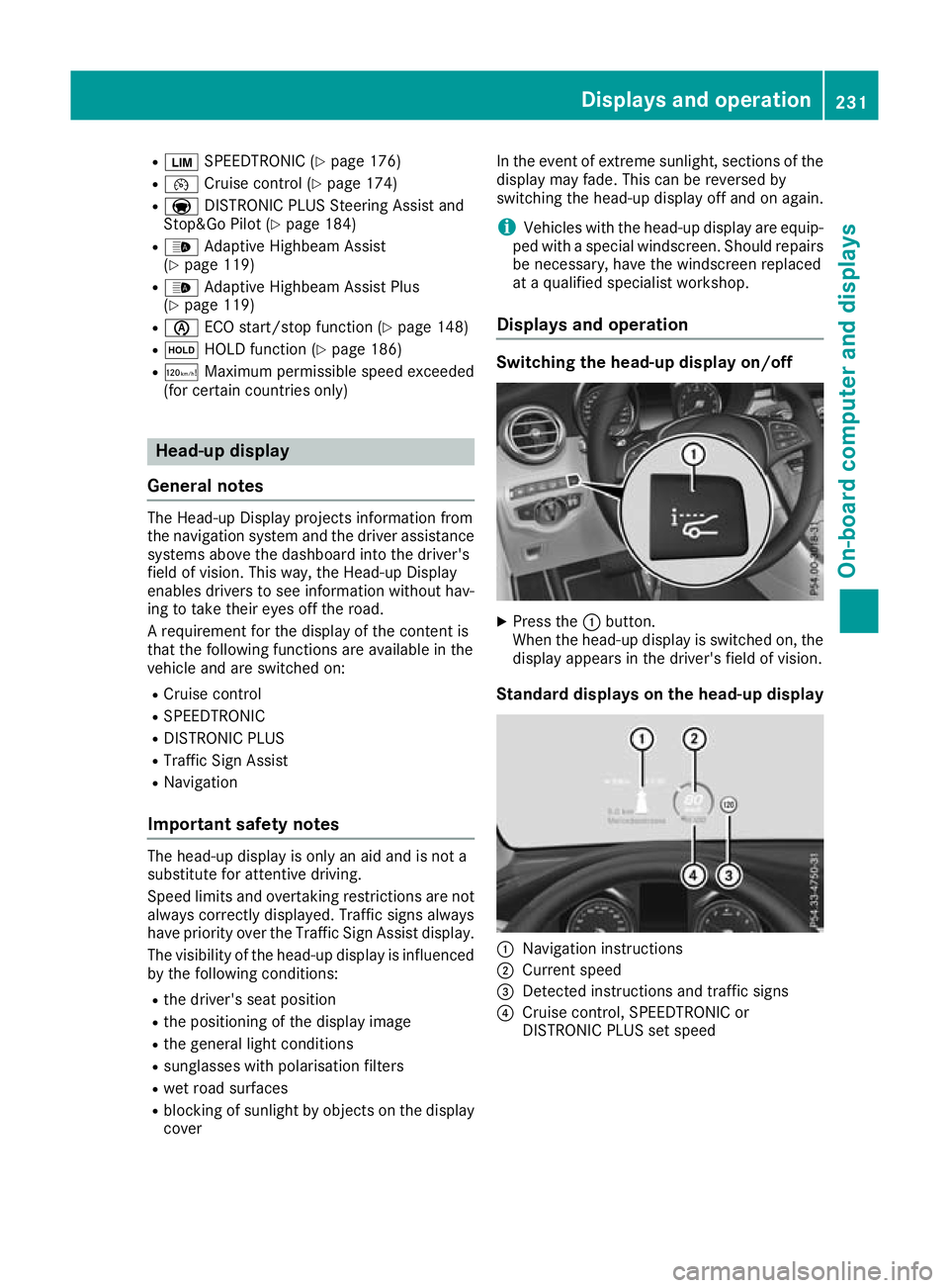
Displays and operation Switching the head-up display on/off
X
Press the :button.
When the head-up display is switched on, the display appears in the driver's field of vision.
Standard displays on the head-up display :
Navigation instructions
; Current speed
= Detected instructions and traffic signs
? Cruise control, SPEEDTRONIC or
DISTRONIC PLUS set speed Displays and operation
231On-board computer and displays Z
Page 243 of 389
X
Confirm by pressing aon the steering
wheel.
The assistance graphic shows you the status
of and/or information from the following driv-
ing systems or driving safety systems:
R DISTRONIC PLUS distance display
(Y page 178)
R Traffic Sign Assist (Y page 208)
R Distance warning function and autono-
mous braking system of COLLISION PRE-
VENTION ASSIST PLUS (Y page 70)
R PRE-SAFE ®
Brake (Y page 77)
R Blind Spot Assist (Y page 210) or Active
Blind Spot Assist (Y page 213)
R ATTENTION ASSIST (Y page 207)
R Lane Keeping Assist (Y page 211) or Active
Lane Keeping Assist (Y page 216)
X Press :to display the ATTENTION ASSIST
assessment. Service menu
Introduction Depending on the equipment fitted in the vehi-
cle, you have the following options in the Ser‐
Ser‐
vice
vice menu:
R Calling up display messages in the message
memory (Y page 249)
R Restarting the tyre pressure loss warning sys-
tem (Y page 361) or checking the tyre pres-
sure electronically (Y page 362)
R Calling up the service due date
(Y page 330)
R Displaying the AdBlue ®
level and range
(Y page 240)
Displaying the AdBlue ®
level and range X
Press òon the steering wheel to open the
menu list.
X Press :or9 on the steering wheel to
select the Service
Service menu.
X Confirm by pressing aon the steering
wheel.
X Press :or9 to select the AdBlue AdBlue
submenu.
X Press ato confirm your selection.
The range and AdBlue ®
level appear in a bar
display in the multifunction display. Observe the information and notes on "Refuel-
ling" (Y
page 164). Settings menu
Introduction Depending on the equipment fitted in the vehi-
cle, you have the following options in the
Set‐ Set‐
tings
tings menu:
R Changing assistance settings (Y page 240)
R Changing Head-up Display settings
(Y page 242)
R Changing the light settings (Y page 243)
R Changing the instrument cluster settings
(Y page 244)
R Changing the vehicle settings (Y page 244)
R Restoring the factory settings (Y page 245)
Assistance submenu Activating/deactivating ESP
®
Observe the "Important safety notes" section in the description of ESP ®
(Y page 73). G
WARNING
If you deactivate ESP ®
, ESP ®
no longer sta-
bilises the vehicle. There is an increased risk
of skidding and an accident.
Only deactivate ESP ®
in the situations descri-
bed in the following.
It may be best to deactivate ESP ®
in the follow-
ing situations:
R when snow chains are used
R in deep snow
R on sand or gravel
Activate/deactivate ESP ®
in Mercedes-AMG
vehicles (Y page 75).
Further information about ESP ®
(Y page 73).
X Start the engine.
X Press òon the steering wheel to open the
menu list.
X Press :or9 on the steering wheel to
select the Settings
Settings menu.
X Confirm by pressing aon the steering
wheel. 240
Menus and submenusOn-board computer and displays
Page 244 of 389
X
Press :or9 to select the Assistance Assistance
submenu.
X Press ato confirm.
X Select ESP ESPwith : or9.
X Press ato confirm.
The current selection appears.
X To activate/deactivate: pressaagain.
If the å warning lamp on the instrument
cluster lights up when the vehicle is ready to
drive, ESP ®
is deactivated.
If the ÷ andå warning lamps light up
continuously, ESP ®
is not available due to a mal-
function.
Observe the information on warning lamps
(Y page 283).
Observe the information on display messages
(Y page 250).
Traffic Sign Assist
You can activate or deactivate the warning func- tion of Traffic Sign Assist in the Traffic
Traffic Sign Sign
Assist
Assist menu. When the message function is
activated, detected traffic signs and information appear in the multifunction display for five sec-
onds.
X Press òon the steering wheel to open the
menu list.
X Press the :or9 button on the steering
wheel to select the Settings
Settings menu.
X Confirm by pressing aon the steering
wheel.
X Press :or9 to select the Assistance
Assistance
submenu.
X Press ato confirm.
X Select Traffic Sign Assist
Traffic Sign Assist with: or
9.
X Press ato confirm.
The current selection appears.
X Activate or deactivate the warning func-
tion: press aagain.
For further information about Traffic Sign Assist, see (Y page 208).
Activating/deactivating COLLISION PRE-
VENTION ASSIST PLUS
X Press òon the steering wheel to open the
menu list.
X Press :or9 on the steering wheel to
select the Settings
Settings menu. X
Confirm by pressing aon the steering
wheel.
X Press :or9 to select the Assistance Assistance
submenu.
X Press ato confirm.
X Select Collision Prevention Collision Prevention with9
or :.
X Press ato confirm.
The current selection appears.
X To activate/deactivate: pressaagain.
When COLLISION PREVENTION ASSIST PLUS
is deactivated, the æsymbol appears in
the multifunction display in the Assistance
Assistance
graphic
graphic menu.
Further information about COLLISION PREVEN- TION ASSIST PLUS (Y page 70).
Activating/deactivating PRE-SAFE ®
Brake
PRE‑SAFE ®
Brake is only available for vehicles
with the Driving Assistance package.
X Press òon the steering wheel to open the
menu list.
X Press :or9 on the steering wheel to
select the Settings
Settings menu.
X Confirm by pressing aon the steering
wheel.
X Press :or9 to select the Assistance
Assistance
submenu.
X Press ato confirm.
X Select with :or9 PRE-SAFE Brake
PRE-SAFE Brake.
X Press ato confirm.
The current selection appears.
X To activate/deactivate: pressaagain.
When PRE-SAFE ®
Brake is deactivated, the
æ symbol appears in the multifunction dis-
play in the Assistance graphic
Assistance graphic menu.
Further information on PRE‑ SAFE®
Brake
(Y page 77).
Activating/deactivating Blind Spot Assist
X Press òon the steering wheel to open the
menu list.
X Press :or9 on the steering wheel to
select the Settings
Settings menu.
X Confirm by pressing aon the steering
wheel.
X Press :or9 to select the Assistance
Assistance
submenu. Menus and submenus
241On-board computer and displays Z