2016 MERCEDES-BENZ G-CLASS SUV phone
[x] Cancel search: phonePage 216 of 261

Note
sono illevel Depending on your drivin
gstyle ,the vehicle
consumes up to 0.8 litres of oi lper 1,000 km.
The oi lconsumption ma ybehighe rtha nt his
when the vehicl eisnew or if yo ufrequentl ydrive
at high engine speeds.
To check the oi llev el:
R park the vehicl eonalevel surface
R the engine shoul dbeswitched off for approx-
imatel yfivem inute sifthe engine is at normal
operating temperature
R if the engine is not at normal operating tem-
perature, e.g .ifthe engine wa sonlys tarted
briefly, wait approximately 30 minute sbefore
carrying out the measurement
Checking the oil level using the oil dip-
stick X
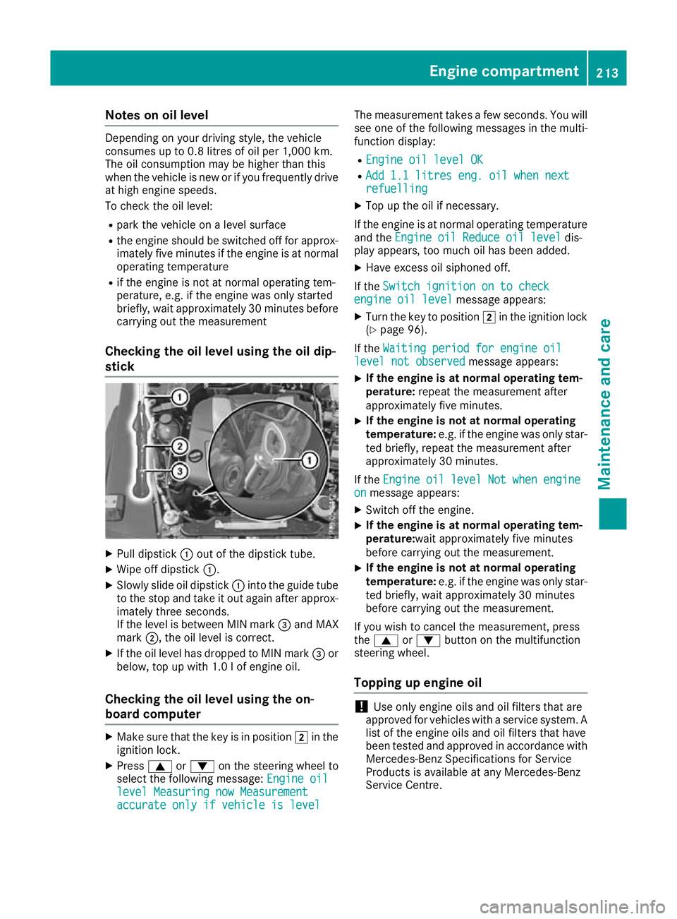
Pull dipstick :out of the dipstick tube.
X Wipe off dipstick :.
X Slowly slide oil dipstick :into the guide tube
to the stop and take it out again after approx- imately three seconds.
If the level is between MIN mark =and MAX
mark ;,the oil level is correct.
X If the oil level has dropped to MIN mark =or
below, top up with 1.0 lofe ngine oil.
Checking the oil level using the on-
board computer X
Make sure that the key is in position 2in the
ignition lock.
X Press 9or: on the steering wheel to
select the following message: Engine oil Engine oil
level Measuring now Measurement level Measuring now Measurement
accurate only if vehicle is level accurate only if vehicle is level The measurement takes
afew seconds. You will
see one of the following messages in the multi-
function display:
R Engine oil level OK Engine oil level OK
R Add 1.1 litres eng. oil when next
Add 1.1 litres eng. oil when next
refuelling refuelling
X Top up the oil if necessary.
If the engine is at normal operating temperature and the Engine oil Reduce oil level
Engine oil Reduce oil level dis-
play appears, too much oil has been added.
X Have excess oil siphoned off.
If the Switch ignition on to check
Switch ignition on to check
engine oil level
engine oil level message appears:
X Turn the key to position 2in the ignition lock
(Y page 96).
If the Waiting period for engine oil
Waiting period for engine oil
level not observed
level not observed message appears:
X If the engine is at normal operating tem-
perature:
repeat the measurement after
approximately five minutes.
X If the engine is not at normal operating
temperature:
e.g. if the engine was only star-
ted briefly, repeat the measurement after
approximately 30 minutes.
If the Engine oil level Not when engine Engine oil level Not when engine
on
on message appears:
X Switch off the engine.
X If the engine is at normal operating tem-
perature:wait approximately five minutes
before carrying out the measurement.
X If the engine is not at normal operating
temperature:
e.g. if the engine was only star-
ted briefly, wait approximately 30 minutes
before carrying out the measurement.
If you wish to cancel the measurement ,press
the 9 or: button on the multifunction
steering wheel.
Topping up engineo il !
Use only engine oils and oil filters that are
approved for vehicles with aservice system. A
list of the engine oils and oil filters that have
been tested and approved in accordance with
Mercedes-Benz Specifications for Service
Products is available at any Mercedes-Benz
Service Centre. Engine compartment
213Maintenance and care Z
Page 217 of 261

The following cause engine failure or damage
to the exhaust system:
R Use of engine oils and oil filters that have
not been expressly approved for the service
system
R Replacement of engine oil and oil filter after
the replacement interval specified by the
service system has expired
R Use of engine oil additives
! Do not add too much oil. If the oil level is
above the "max" mark on the dipstick ,too
much oil has been added. This can lead to
damage to the engine or the catalytic con-
verter .Have excess oil siphoned off. H
Environmental note
When topping up the oil, take care not to spill
any. If oil enters the soil or waterways, it is
harmful to the environment. X
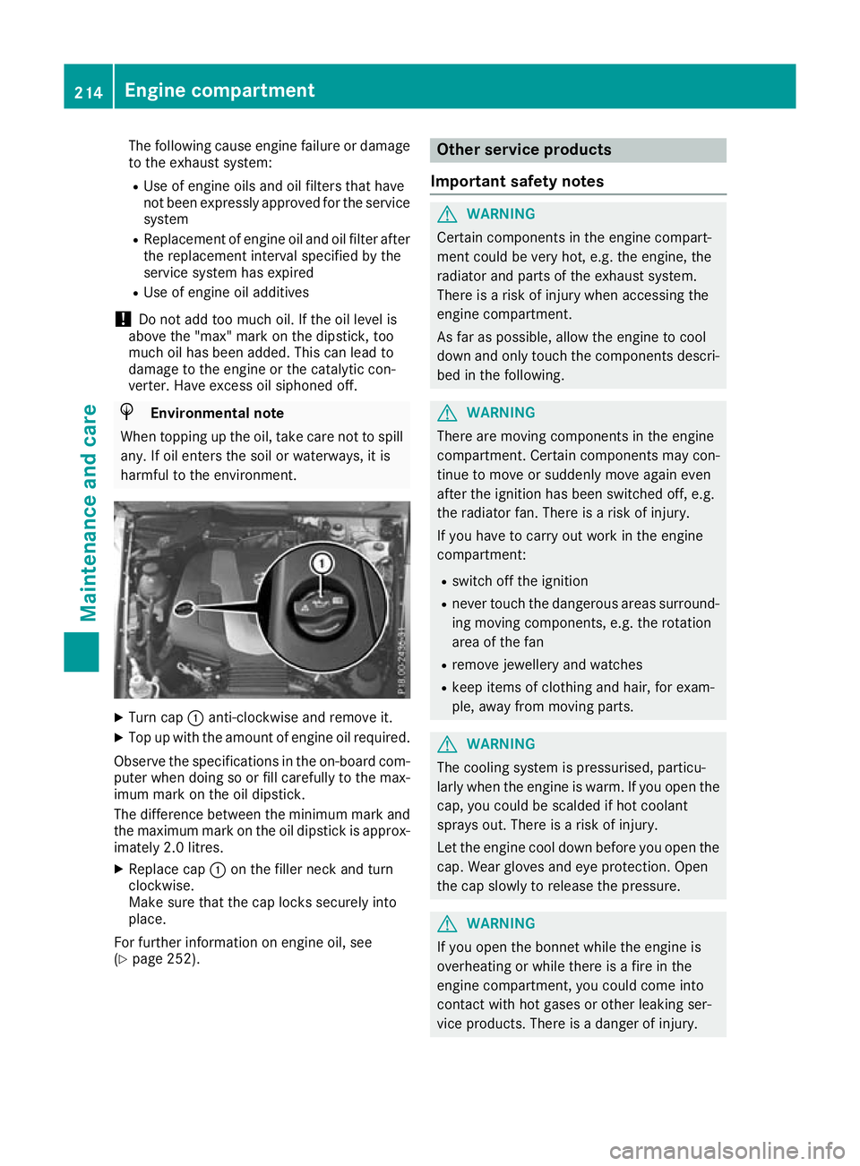
Turn cap :anti-clockwise and remove it.
X Top up with the amount of engine oil required.
Observe the specification sinthe on-board com-
puter when doing so or fill carefully to the max- imum mark on the oil dipstick.
The differenc ebetween the minimum mark and
the maximum mark on the oil dipstick is approx- imately 2.0 litres.
X Replace cap :on the filler neck and turn
clockwise.
Make sure that the cap locks securely into
place.
For further information on engine oil, see
(Y page 252). Other service products
Important safety notes G
WARNING
Certain components in the engin ecompart-
ment coul dbevery hot, e.g. the engine, the
radiator and parts of the exhaust system.
There is arisk of injury when accessing the
engine compartment.
As far as possible,a llow the engine to cool
downa nd only touch the components descri-
bed in the following. G
WARNING
There are moving components in the engine
compartment. Certain components may con-
tinue to move or suddenly move again even
after the ignitio nhas been switched off, e.g.
the radiator fan. There is arisk of injury.
If you have to carry out work in the engine
compartment:
R switch off the ignition
R never touch the dangerous area ssurround-
ing moving components, e.g. the rotation
area of the fan
R remove jewellery and watches
R keep items of clothing and hair, for exam-
ple,a wayfrom moving parts. G
WARNING
The cooling system is pressurised ,particu-
larl yw hen the engine is warm .Ifyou open the
cap, you coul dbescalded if hot coolant
sprays out. There is arisk of injury.
Let the engine cool downb efore you open the
cap. Wearg lovesand eye protection. Open
the cap slowly to release the pressure. G
WARNING
If you open the bonnet while the engine is
overheating or while there is afire in the
engine compartment, you coul dcome into
contact with hot gase sorother leaking ser-
vice products. There is adange rofinjury. 214
Engine compartmentMaintenanc
eand care
Page 243 of 261

For further information on displaying this mes-
sage, refe rtothe "Checking the tyre pressure
electronically" section (Y page 240).
Important safety notes It is the driver's responsibility to set the tyre
pressure to the recommended cold tyre pres-
sure suitable for the operating situation
(Y page 238). Note that the correc ttyre pres-
sure for the current operating situation must
first be learnt by the tyre pressure monitor. If a
substantial loss of pressure occurs, the warning threshold for the warning message is aligned to
the learnt reference values. Restart the tyre
pressure monitor after adjusting to the cold tyre pressure (Y page 241). The current pressures
are saved as new reference values. This ensures that awarning message appears only if the tyre
pressure drops significantly.
The tyre pressure monitor does not warn you of
an incorrectly set tyre pressure. Observe the
notes on the recommended tyre pressure
(Y page 238).
The tyre pressure monitor is not abletow arn
you of asudden loss of pressure, e.g. if the tyre
is penetrated by aforeign object. In this event,
bring the vehicle to ahalt by braking carefully.
Avoid abrupt steering manoeuvres.
The tyre pressure monitor has ayellow h
warning lamp on the instrument cluster for indi-
cating apressure loss or malfunction. Depend-
ing on how the warning lamp flashe sorlights up,
at yre pressure that is too low or amalfunction in
the tyre pressure monitor is indicated:
R if the h warning lamp is lit continuously,
the tyre pressure on one or more tyres is sig-
nificantly too low. The tyre pressure monitor
is not malfunctioning.
R if the h warning lamp flashe sfor around a
minute and then remains lit constantly, the
tyre pressure monitor is malfunctioning.
In addition to the hwarning lamp,am essage
appears in the multifunction display. Observe
the information on display messages
(Y page 150).
It may take up to ten minutes for amalfunction
of the tyre pressure monitor to be indicated .A
malfunction willbei ndicated by thehtyre
pressure warning lamp flashing for approx-
imatel yone minute and then remaining lit. When
the faulth as been rectified, the htyre pres-
sure warning lamp goes out after driving for a
few minutes. The tyre pressure values indicated by the on-
board computer may differ from those meas-
ured at
afilling station using apressure gauge.
The tyre pressures shown by the on-board com-
puter refer to those measured at sea level. At
high altitudes, the tyre pressure values indica-
ted by apressure gauge are higher than those
shown by the on-board computer. In this case,
do not reduce the tyre pressures.
The operation of the tyre pressure monitor can
be affected by interferenc efrom radio transmit-
ting equipment (e.g. cordless headphones, two- way radios) that may be being operated in or
near the vehicle.
Checking the tyrep ressureelectroni-
cally X
Make sure that the key is in position 2in the
ignition lock.
X Press the =or; button on the steering
wheel to select the Serv.
Serv. menu.
X Press the 9or: button to select
Tyre pressure
Tyre pressure.
X Press the abutton.
The multifunction display shows the current
tyre pressure of each wheel.
If the vehicle has been parked for over
20 minutes, the Tyre pressures will be Tyre pressures will be
displayed
displayed after a
after afew
fewminutes
minutes of
ofdriv‐
driv‐
ing
ing message appears.
After ateach-in period, the tyre pressure moni-
tor automaticallyd etects new wheels or new
sensors. As long as aclear allocation of the tyre
pressure valuestot he individual wheels is not
possible,t heTyre
Tyre pressure
pressure monitor
monitoractive
active
displaym essage is shown instead of the tyre
pressure display. The tyre pressures are already being monitored.
If as pare wheel is fitted, the system may con-
tinue to show the tyre pressure of the wheel that has been removed for afew minutes. Please
note that in this case, the value displayed for the
replaced wheel does not indicate the current
tyre pressure of the spare wheel.
Warning messages of the tyre pressure monitor If the tyre pressure monitor detects
apressure
loss in one or more tyres, awarning messag eis
shown on the multifunction display. The yellow
h tyre pressure warning lamp then lights up. 240
Tyre pressureWheels and tyres
Page 251 of 261

Information on technica
ldata
i The technical dat
awere determine din
accordanc ewithEUD irectives .All dat aapply
to th evehicle's standard equipment. The data
may therefor ediffer for vehicles wit hoptional
equipment. You can obtain further informa-
tion from aMercedes-Ben zServic eCentre. Vehicle electronics
Tampering with th
eengin eelect ron-
ics
! Onl
yhavew orkc arrie douton the engine
electronics and its associated parts, such as
contro lunits, sensors, actuating components
and connector leads, at aquali fied specialist
workshop .Vehicl ecomponents ma yother-
wise wear mor equickl yand the vehicle's
operating permi tmaybe invalidated. Fittin
gtwo-way radios and mobile
phones (RF transmitters) G
WARNING
If RF transmitters ar etampere dwith or not
properly retrofitted, the electromagnetic radi- ation they emit can interfere with the vehicle
electronics. This may jeopardise the opera-
tional safety of the vehicle. There is arisk of an
accident.
You should have all work on electrica land
electronic components carrie dout at aquali-
fied specialist workshop. G
WARNING
If you operate RF transmitters incorrectly in
the vehicle, the electromagnetic radiation
coul dinterfere with the vehicl eelectronics,
e.g.:
R if the RF transmitter is not connected to an
exterior aerial
R the exterior aerial has been fitted incor-
rectly or is not alow-reflection type
This coul djeopardise the operating safety of
the vehicle. There is arisk of an accident. Have the low-reflection exterior aeria
lfitted at
aq ualifie dspecialist workshop .Wheno per-
ating RF transmitters in the vehicle, always
connect them to the low-reflection exterior
aerial.
! The operating permit may be invalidated if
the instructions for installatio nand use of RF
transmitters are not observed.
In particular, the following conditions mus tbe
complied with:
R only approve dwavebands may be used.
R observe the maximum permissibl eoutput
in these wavebands.
R only approve daerialp ositions may be
used.
Excessive levels of electromagnetic radiation
may cause damag etoyourh ealth and to the
health of others .The use of an exterior aerial
takes into consideration the scientific discus-
sio ns urrounding the possible health risk posed
by electromagnetic fields. Approve
daerialp ositions
: Front roo farea
; Rear wings
Whe nfitting an aeria lonthe front roo fareaof
vehicles with aslidin gsunroof, observe the
sweeping rang eofthe roof.
On the rea rwings, it is recommended tha tyou
position the aeria lonthe side of the vehicle
closes ttothe centre of the road.
Use Technical Specification ISO/T S21609
(Roa dVehicles –"EM Cg uideli nesfor installa-
tio nofa ftermarket radio frequency transmitting
equipment") when retrofitting RF transmitters
(radi ofrequency) .Com plyw itht he lega lrequire-
ments for add-on parts.
If your vehicl ehasfittings for two-wa yradio
equipment, us ethe power supply or aeria lcon- 248
Vehiclee
lectronicsTechnical data
Page 252 of 261

nections intende
dfor us ewitht he basi cfittings.
Be sure to observe the manufacturer' saddi-
tional instructions when installing.
Deviations in respect of wavebands, maximum
transmission outputs or aeria lpositions must be
approved by Mercedes-Benz.
The maximu mtransmission outpu t(PE AK) at the
base of the aeria lmustn ot exceed the following
values: Waveband Maximum
transmissi on
output Short wave
3-54M
Hz 100 W
4mw
aveband
68 -87.5 MHz 30 W
2mw
aveband
144 -174 MHz 50 W
Trunked radio/Tetra
380
-460 MHz 10 W
70 cm waveband
400
-460 MHz 35 W
Mobilec
ommunications
(2G/3G/4G) 10 W
The following can be used in the vehicle without
restrictions:
R RF transmitters with amaximum transmis-
sion output of up to 100 mW
R RF transmitters with transmitter frequencies
in the 380 –410 MHz waveband and amaxi-
mum transmission output of up to 2W
(trunked radio/Tetra)
R Mobile phones (2G/3G/4G)
There are no restriction swhen positionin gthe
aerial on the outside of the vehicle for the fol-
lowing wavebands:
R Trunked radio/Tetra
R 70 cm waveband
R 2G/3G/4G Identification plates
Veh
icle identificatio nplate with vehi-
cl ei dentificatio nnumber (VIN) X
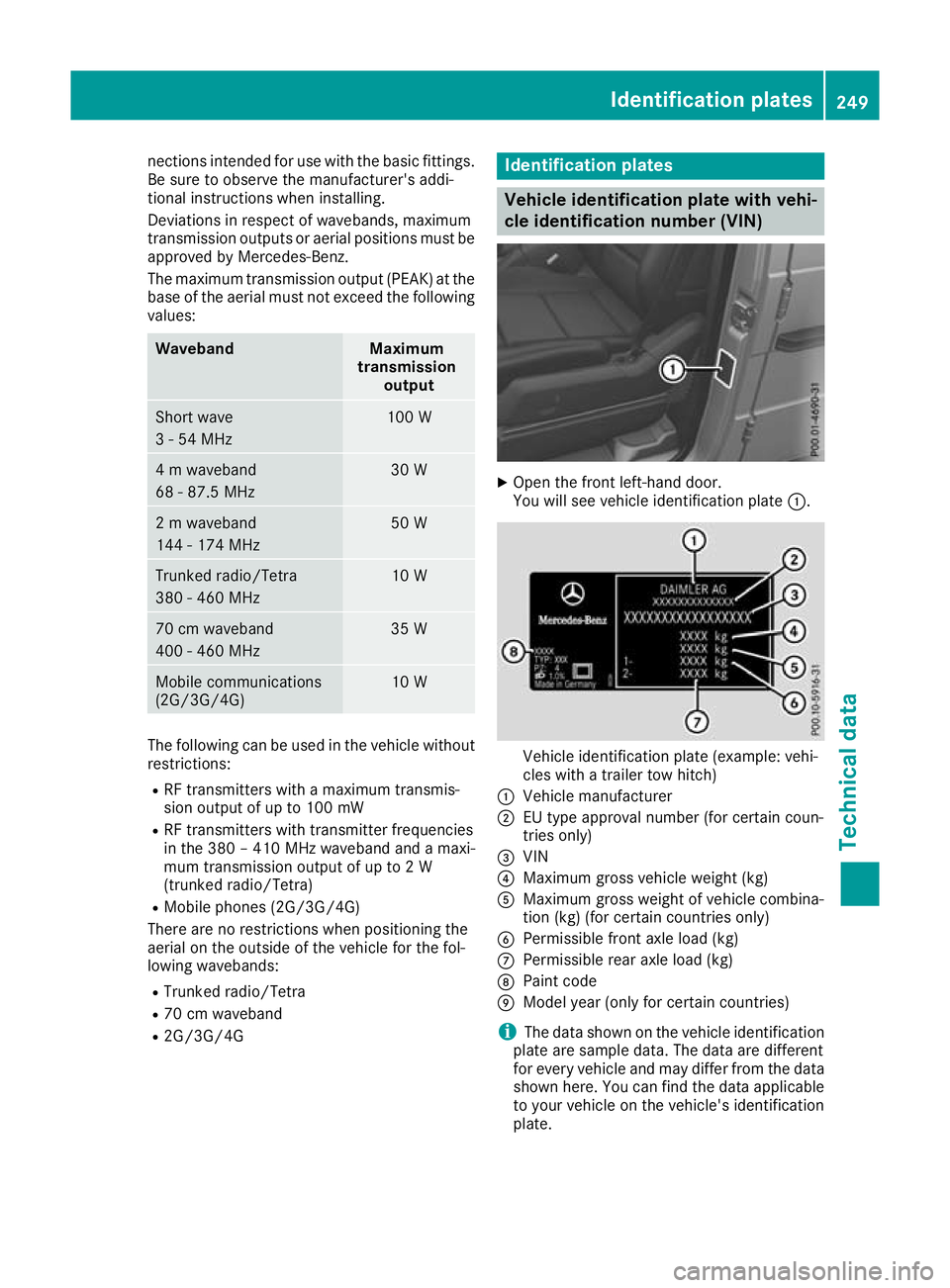
Ope nthe front left-hand door.
You will see vehicle identification plate :. Vehicle identification plate (example: vehi-
cles with
atrailer tow hitch)
: Vehicle manufacturer
; EU type approvaln umber (for certain coun-
tries only)
= VIN
? Maximum gross vehicle weight( kg)
A Maximum gross weightofv ehicle combina-
tion (kg) (for certain countries only)
B Permissiblef ront axle load (kg)
C Permissibler ear axle load (kg)
D Paint code
E Model year( only for certain countries)
i The data shown on the vehicle identification
plate are sample data. The data are different
for every vehicle and may differ from the data shown here. You can find the data applicable
to yourv ehicle on the vehicle's identification
plate. Identification plates
249Technical data Z