2016 MERCEDES-BENZ G-Class steering
[x] Cancel search: steeringPage 230 of 302

You can find further information on the mbrace
system athttp://www.mbusa.com2Log in
under "Owners Online".
iIf the indicator lamp in MB Info call but-
ton :is flashing continuously and no voice
connection with the Response center has
been established, then the mbrace system
has not been able to initiate an MB Info call
(e.g. the relevant mobile phone network is not
available). The Call Failed
message
appears in the multifunction display.
XTo end a call: press the~button on the
multifunction steering wheel.
or
XPress the corresponding COMAND button to
end a phone call.
Call priority
When service calls are active, e.g. Roadside
Assistance or MB Info calls, an emergency call
can still be initiated. In this case, an emergency
call will take priority and override all other active
calls.
The indicator lamp of the respective button
flashes until the call is ended. An emergency call
can only be terminated by the Response Center.
All other calls can be ended by pressing the
~ button on the multifunction steering wheel
or the corresponding COMAND button for end-
ing a telephone call.
iWhen an mbrace call is initiated, COMAND
is muted. The mobile phone is no longer con-
nected to COMAND.
However, if you want to use your mobile
phone, do so only when the vehicle is station-
ary and in a safe location.
Downloading destinations in COMAND
Destination Download gives you access to a
database with over ten million points of interest
(POIs) which can be downloaded onto the navi-
gation system of your vehicle. If you know the
destination, you can download the address or
obtain the location of points of interest (POIs) or
important destinations in the surrounding area. You are prompted to confirm route guidance to
the address entered.
iFor information on the components and
operating principles of COMAND, (see the
separate operating instructions).
XSelect Yesusing the =or; buttons on
COMAND.
XConfirm using the 9button on COMAND.
The system calculates the route and subse-
quently starts the route guidance with the
address entered.
iIf you select No, the address can be stored in
the address book.
iThe Destination Download function is avail-
able if the corresponding mobile phone net-
work is available and data transfer is possible.
Search & Send
"Search & Send" is a destination entry service.
For more information on "Search & Send", see
the separate operating instructions.
Vehicle remote opening
If you have unintentionally locked your vehicle
(e.g. the SmartKey is inside the vehicle) and a
replacement key is not available:
XContact the following service hotlines:
RUSA: Response Center at
1-888-990-9007
RCanada: Customer Service at
1-888-923-8367
You will be asked for your password.
XReturn to your vehicle at the time arranged
with the Response Center.
XPress the release button on the door handle of
the rear door for at least 20 seconds until the
indicator lamp in the SOS button (
Ypage 225)
flashes.
The Connecting Call
message appears on
the multifunction display.
Alternatively, the vehicle can be opened via the
Internet in the "Owner's Online" section using
your identification number and password
3.
2USA only.3USA only.
228Features
Stowage and features
Page 239 of 302

When checking the oil level:
Rpark the vehicle on a level surface.
Rthe engine should be switched off for approx-
imately five minutes if the engine is at normal
operating temperature.
Rthe engine should be switched off for at least
30 minutes if the engine is not at operating
temperature, e.g. if you only start the engine
briefly.
XPull oil dipstick :out of the dipstick guide
tube.
XWipe off oil dipstick :.
XSlowly slide oil dipstick :into the guide tube
to the stop, and take it out again.
If the level is between MIN mark =and MAX
mark ;, the oil level is correct.
XAdd oil if necessary.
On all other models, the on-board computer
must be used to check the engine oil level.
Checking the oil level using the on-
board computer
!Do not add too much oil. adding too much
engine oil can result in damage to the engine
or to the catalytic converter. Have excess
engine oil siphoned off.
G 550: the oil level can only be checked using
the on-board computer.
When checking the oil level:
Rpark the vehicle on a level surface.
Rthe engine should be switched off for approx-
imately five minutes if the engine is at normal
operating temperature.
XMake sure that the SmartKey is in position 2
in the ignition lock.
XPress the 9or: button on the steering
wheel to select the following message:
The measurement takes a few seconds. You will
see one of the following messages in the multi-
function display:
REngine Oil Level OK
RAdd1.0qt(Canada: 1.0liter)toreachmaximum oil level
RAdd 1.5 qts(Canada: 1.5 liters)toreach maximum oil level
RAdd 2.0 qts.(Canada: 2.0 liters)toreach maximum oil level
XAdd oil if necessary.
If the engine is at normal operating temperature and the Engine oil Reduce oil level
dis-
play appears, too much oil has been added.
XHave excess oil siphoned off.
If the Switch ignition on to check
engine oil levelmessage appears:
XTurn the SmartKey to position 2in the ignition
lock (Ypage 112).
If the Observe waiting time
message
appears:
XIf the engine is at normal operating tem-
perature: repeat the measurement after
approximately five minutes.
XIf the engine is not at normal operating
temperature: e.g. if the engine was only star-
ted briefly, repeat the measurement after
approximately 30 minutes.
If the Engine oil level Not when engine
onmessage appears:
XSwitch off the engine.
XIf the engine is at normal operating tem-
perature: wait about five minutes before car-
rying out the measurement.
XIf the engine is not at normal operating
temperature: e.g. if the engine was only star-
ted briefly, wait approximately 30 minutes
before carrying out the measurement.
iIf you wish to cancel the measurement,
press the 9or: button on the multi-
function steering wheel.
Adding engine oil
GWARNING
Certain components in the engine compart-
ment, such as the engine, radiator and parts
of the exhaust system, can become very hot.
Engine compartment237
Maintenance and care
Z
Page 242 of 302

Further information on windshield washer fluid/
antifreeze (Ypage 295).
Brake fluid level
!If you notice that the brake fluid level in the
brake fluid reservoir has fallen to the MIN
mark or less, check the brake system imme-
diately for leaks. Also check the thickness of
the brake linings. Visit a qualified specialist
workshop immediately.
Do not add brake fluid. This does not correct
the error.
Only check the brake fluid level when the vehicle
is on a level surface.
If the brake fluid level is between MIN mark :
and MAX mark ;on the brake fluid reservoir, it
is correct.
Maintenance
Service interval display
Service messages
Information on the type of service and service
intervals (see the separate Maintenance Book-
let).
You can obtain further information from an
authorized Mercedes-Benz Center or at
http://www.mbusa.com (USA only).
The ASSYST service interval display informs you
of the next service due date.
If a service due date has been exceeded, you
also hear a warning tone.
The multifunction display shows a service mes-
sage for several seconds, e.g.:
Service A in 99999 Miles
Service A Due Now
Service A Exceeded By 99999 Miles
Maintaining the time-dependent service sched-
ule:
XBefore disconnecting the battery, note down
the service due date displayed.
or
XAfter reconnecting the battery, subtract the
battery disconnection periods from the ser-
vice date shown on the display.
iThe service interval display should not be
confused with the 4engine oil level dis-
play.
The symbol and the letter indicate which type of
service is due:
¯ Minor service A
±
Major service B
The ASSYST service interval display does not
take into account any periods of time during
which the battery is disconnected.
Hiding a service message
XTo hide the service message, press the %
back button on the multifunction steering
wheel (
Ypage 29)(Ypage 172).
Displaying service messages
Use the buttons on the multifunction steering
wheel.
XSwitch on the ignition.
XPress =or; to select the standard
display menu on the steering wheel
(
Ypage 173).
XPress 9or: to select the service
interval display.
The ¯ or± service symbol and the ser-
vice due date are displayed.
Points to remember
The specified maintenance interval takes only
the normal operation of the vehicle into
account. Under arduous operating conditions or
increased load on the vehicle, maintenance
work must be carried out more frequently, for
example:
Rregular city driving with frequent intermediate
stops
Rif the vehicle is primarily used to travel short
distances
240Maintenance
Maintenance and care
Page 248 of 302

Cleaning the steering wheel and gear or
selector lever
XThoroughly wipe with a damp cloth or use
leather care agents that have been recom-
mended and approved by Mercedes-Benz.
Cleaning genuine wood and trim strips
!Do not use solvent-based cleaning agents
such as tar remover, wheel cleaners, polishes
or waxes. There is otherwise a risk of damag- ing the surface.
!Do not use chrome polish for trim strips. The
trim strips have a chrome look but are mostly
made of anodized aluminum and can lose
their shine if chrome polish is used. Use a
damp, lint-free cloth instead when cleaning
the trim strips.
If the chrome-plated trim strips are very dirty,
you can use a chrome polish. If you are unsure
as to whether the trim strips are chrome-
plated or not, consult an authorized
Mercedes-Benz Center.
XWipe the wooden trim and trim strips with a
damp, lint-free cloth, e.g. a microfiber cloth.
XHeavy soiling: use car care and cleaning
products recommended and approved by
Mercedes-Benz.
Cleaning the seat covers
General notes
!Do not use microfiber cloths to clean genu-
ine leather, artificial leather or DINAMICA
covers. If used often, these can damage the
cover.
iNote that regular care is essential to ensure
that the appearance and comfort of the cov-
ers is retained over time.
Genuine leather seat covers
!To retain the natural appearance of the
leather, observe the following cleaning
instructions:
RClean genuine leather covers carefully with
a damp cloth and then wipe the covers
down with a dry cloth.
RMake sure that the leather does not
become soaked. It may otherwise become
rough and cracked.
ROnly use leather care agents that have
been tested and approved by Mercedes-
Benz. You can obtain these from a qualified
specialist workshop.
Leather is a natural product.
It exhibits natural surface characteristics, for
example:
Rdifferences in the texture
Rmarks caused by growth and injury
Rslight nuances of color
These are characteristics of leather and not
material defects.
Seat covers of other materials
!Observe the following when cleaning:
Rclean artificial leather covers with a cloth
moistened with a solution containing 1%
detergent (e.g. dish washing liquid).
Rclean cloth covers with a microfiber cloth
moistened with a solution containing 1%
detergen
t (e.g. dish washing liquid). Rub
carefully and always wipe entire seat sec-
tions to avoid leaving visible lines. Leave
the seat to dry afterwards. Cleaning results
depend on the type of dirt and how long it
has been there.
Rclean DINAMICA covers with a damp cloth.
Make sure that you wipe entire seat sec-
tions to avoid leaving visible lines.
Cleaning the seat belts
GWARNING
Seat belts can become severely weakened if
bleached or dyed. This could cause the seat
belts to tear or fail, for instance, in the event of an accident. This poses an increased risk of
injury or fatal injury.
Never bleach or dye the seat belts.
246Care
Maintenance and care
Page 252 of 302

iWhen re-installing trim panel?, make sure
that retainer Aengages in recess B.
Removing the spare wheel
The spare wheel is heavy. Take particular note of
this when removing the spare wheel.
XRemove wheel nuts :.
XRemove the spare wheel.
Mounting the wheel
After changing a wheel:
XRepair or replace the damaged wheel as soon
as possible and secure the spare wheel in
place again.
XSecure the damaged wheel on the spare
wheel bracket with wheel nuts :. When
doing so, make sure that the wheel cannot
come loose.
XWhen re-installing trim panel ?, make sure
that retainer Bengages in recess A
(
Ypage 249).
XMake sure that tab ;is below when re-
installing cover ring :(Ypage 249).
XFor safety reasons, regularly check to ensure
that the wheel is securely fastened.
Flat tire
Preparing the vehicle
XStop the vehicle on solid, non-slippery and
level ground, as far away as possible from
traffic.
XSwitch on the hazard warning lamps
(Ypage 89).
XApply the parking brake.
XBring the front wheels into the straight-ahead
position.
XMove the selector lever to position P.
XSwitch off the engine.
XRemove the SmartKey from the ignition lock.
The steering wheel lock stays active for as
long as the SmartKey is removed.
XAll occupants must get out of the vehicle.
Make sure that they are not endangered as
they do so.
XMake sure that no one is near the danger area
while a wheel is being changed. Anyone who
is not directly assisting in the wheel change
should, for example, stand behind the barrier.
XGet out of the vehicle. Pay attention to traffic
conditions when doing so.
XClose the driver's door.
Battery (vehicle)
Important safety notes
Special tools and expert knowledge are required
when working on the battery, e.g. removal and
installation. You should therefore have all work
involving the battery carried out at a qualified
specialist workshop.
GWARNING
Work carried out incorrectly on the battery
can lead, for example, to a short circuit and
thus damage the vehicle electronics. This can
lead to function restrictions applying to
safety-relevant systems, e.g the lighting sys-
tem, the ABS (anti-lock braking system) or the
ESP
®(Electronic Stability Program). The oper-
ating safety of your vehicle may be restricted.
You could lose control of the vehicle, for
example:
Rwhen braking
Rin the event of abrupt steering maneuvers
and/or when the vehicle's speed is not
adapted to the road conditions
There is a risk of an accident.
In the event of a short circuit or a similar inci-
dent, contact a qualified specialist workshop
immediately. Do not drive any further. You
250Battery (vehicle)
Breakdown assistance
Page 258 of 302

XLift up cover:of positive terminal ;in the direction of the arrow.
XConnect positive terminal ;on your vehicle to positive terminal ?of donor battery Busing the
jumper cable. beginning with your own battery.
XStart the engine of the donor vehicle and run it at idling speed.
XConnect negative terminal Aof donor battery Bto ground point =of your vehicle using the
jumper cable, connecting the jumper cable to donor battery Bfirst.
XStart the engine.
XFirst, remove the jumper cables from ground point =and negative terminal A, then from pos-
itive clamp ;and positive terminal ?. Each time beginning with your vehicle's battery.
XHave the battery checked at a qualified specialist workshop.
iJump-starting is not considered to be a normal operating condition.
iJumper cables and further information regarding jump-starting can be obtained at any qualified
specialist workshop.
Towing and tow-starting
Important safety notes
GWARNING
Functions relevant to safety are restricted or
no longer available if:
Rthe engine is not running.
Rthe brake system or the power steering is
malfunctioning.
Rthere is a malfunction in the voltage supply or the vehicle's electrical system.
If your vehicle is being towed, much more
force may be necessary to steer or brake.
There is a risk of an accident.
In such cases, use a tow bar. Before towing,
make sure that the steering moves freely.
GWARNING
When towing or tow-starting another vehicle
and its weight is greater than the permissible
gross weight of your vehicle, the:
Rthe towing eye could detach itself
Rthe vehicle/trailer combination could roll-
over.
There is a risk of an accident.
When towing or tow-starting another vehicle,
its weight should not be greater than the per- missible gross weight of your vehicle.
!If DISTRONIC PLUS or the HOLD function is
activated, the vehicle brakes automatically in
certain situations. To prevent damage to the
vehicle, deactivate DISTRONIC PLUS and the
HOLD function in the following or other simi-
lar situations:
Rwhen towing the vehicle
Rin the car wash
!The vehicle can be towed a maximum of
30 miles (50km). The towing speed of 30 mph
(50 km/h) must not be exceeded.
If the vehicle has to be towed more than
30 miles (50km), the entire vehicle must be
raised and transported.
!Only secure the tow cable or tow bar to the
towing eyes. You could otherwise damage the
vehicle.
!Do not tow with sling-type equipment. This
could damage the vehicle.
!Do not use the towing eyes for recovery pur-
poses as this could damage the vehicle. If in
doubt, recover the vehicle with a crane.
!When towing, pull away slowly and
smoothly. If the tractive power is too high, the
vehicles could be damaged.
!Your vehicles is equipped with an automatic
transmission. Therefore, you must not have
the vehicle tow-started. The transmission
may otherwise be damaged.
iDetails on the permissible gross vehicle
weight of your vehicle can be found on the
vehicle identification plate (
Ypage 288).
256Towing and tow-starting
Breakdown assistance
Page 260 of 302

Transporting the vehicle
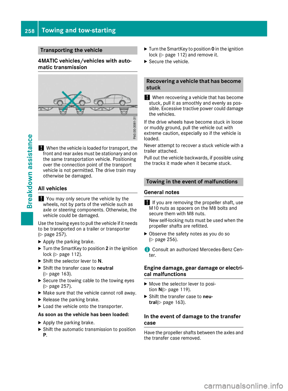
4MATIC vehicles/vehicles with auto-
matic transmission
!When the vehicle is loaded for transport, the
front and rear axles must be stationary and on the same transportation vehicle. Positioning
over the connection point of the transport
vehicle is not permitted. The drive train may
otherwise be damaged.
All vehicles
!You may only secure the vehicle by the
wheels, not by parts of the vehicle such as
axle or steering components. Otherwise, the
vehicle could be damaged.
Use the towing eyes to pull the vehicle if it needs
to be transported on a trailer or transporter
(
Ypage 257).
XApply the parking brake.
XTurn the SmartKey to position 2in the ignition
lock (Ypage 112).
XShift the selector lever to N.
XShift the transfer case toneutral
(Ypage 163).
XSecure the towing cable to the towing eyes
(Ypage 257).
XMake sure that the vehicle cannot roll away.
XRelease the parking brake.
XLoad the vehicle onto the transporter.
As soon as the vehicle has been loaded:
XApply the parking brake.
XShift the automatic transmission to position
P .
XTurn the SmartKey to position 0in the ignition
lock (Ypage 112) and remove it.
XSecure the vehicle.
Recovering a vehicle that has become
stuck
!
When recovering a vehicle that has become
stuck, pull it as smoothly and evenly as pos-
sible. Excessive tractive power could damage
the vehicles.
If the drive wheels have become stuck in loose
or muddy ground, pull the vehicle out with
extreme caution, especially so if the vehicle is
loaded.
Never attempt to recover a stuck vehicle with a
trailer attached.
Pull out the vehicle backwards, if possible using the tracks it made when it became stuck.
Towing in the event of malfunctions
General notes
!If you are removing the propeller shaft, use
M10 nuts as spacers on the M8 bolts and
secure them with M8 nuts.
New self-locking nuts must be used when the
propeller shafts are refitted.
XObserve the safety notes as you do so
(Ypage 256).
iConsult an authorized Mercedes-Benz Cen-
ter.
Engine damage, gear damage or electri-
cal malfunctions
XMove the selector lever to posi-
tion N(Ypage 119).
XShift the transfer case to neu-
tral (Ypage 163).
In the event of damage to the transfer
case
Have the propeller shafts between the axles and
the transfer case removed.
258Towing and tow-starting
Breakdown assistance
Page 265 of 302

severe corrosion on wheels, for example.
Damaged wheels can cause a loss of tire pres-
sure.
RRegularly check the tire tread depth and the
condition of the tread across the whole width
of the tire (
Ypage 263). In order to inspect
the inner side of the tire surface, turn the
steering wheel to full lock.
RAll wheels must have a valve cap to protect
the valve against dirt and moisture. Do not
install anything onto the valve other than the
standard valve cap or a valve cap approved by Mercedes-Benz for your vehicle.
Do not install anything onto the valve, such as
tire pressure monitoring systems.
RYou should regularly check the pressure of all
your tires including the spare wheel, particu-
larly prior to long trips. Adjust the tire pres-
sure as necessary (
Ypage 270).
The service life of tires depends, among other
things, on the following factors:
RDriving style
RTire pressure
RDistance covered
Tire tread
GWARNING
Insufficient tire tread will reduce tire traction.
The tire is no longer able to dissipate water.
This means that on wet road surfaces, the risk
of hydroplaning increases, in particular where speed is not adapted to suit the driving con-
ditions. There is a risk of accident.
If the tire pressure is too high or too low, tires
may exhibit different levels of wear at differ-
ent locations on the tire tread. Thus, you
should regularly check the tread depth and
the condition of the tread across the entire
width of all tires.
Minimum tire tread depth for:
RSummer tires: âin (3 mm)
RM+S tires: ãin (4 mm)
For safety reasons, replace the tires before
the legally prescribed limit for the minimum
tire tread depth is reached.
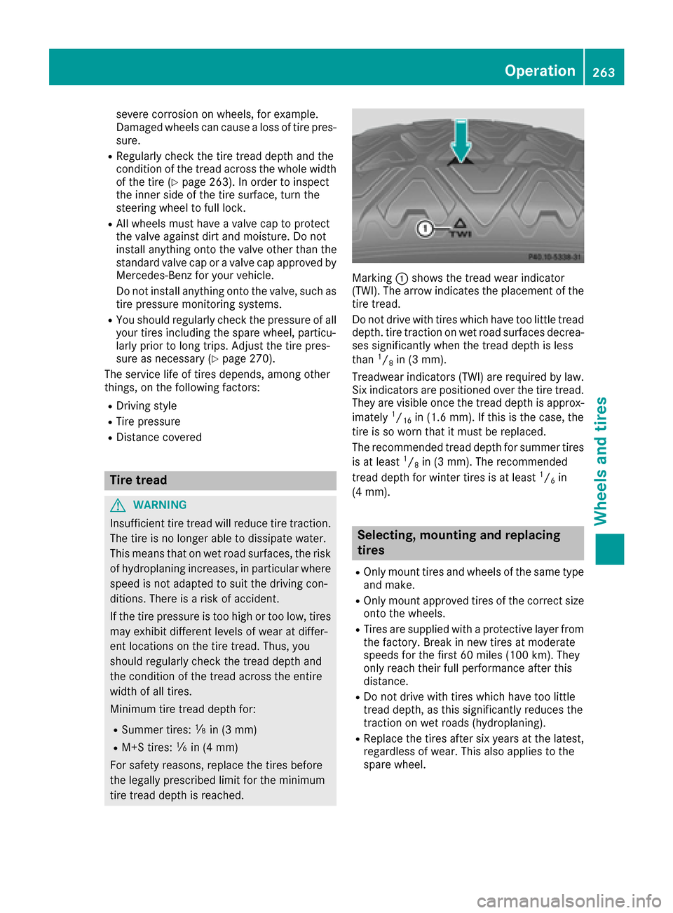
Marking :shows the tread wear indicator
(TWI). The arrow indicates the placement of the
tire tread.
Do not drive with tires which have too little tread
depth. tire traction on wet road surfaces decrea-
ses significantly when the tread depth is less
than
1/8in (3 mm).
Treadwear indicators (TWI) are required by law.
Six indicators are positioned over the tire tread.
They are visible once the tread depth is approx-
imately
1/16in (1.6 mm). If this is the case, the
tire is so worn that it must be replaced.
The recommended tread depth for summer tires
is at least
1/8in (3 mm). The recommended
tread depth for winter tires is at least1/6in
(4 mm).
Selecting, mounting and replacing
tires
ROnly mount tires and wheels of the same type
and make.
ROnly mount approved tires of the correct size
onto the wheels.
RTires are supplied with a protective layer from
the factory. Break in new tires at moderate
speeds for the first 60 miles (100 km). They
only reach their full performance after this
distance.
RDo not drive with tires which have too little
tread depth, as this significantly reduces the
traction on wet roads (hydroplaning).
RReplace the tires after six years at the latest,
regardless of wear. This also applies to the
spare wheel.
Operation263
Wheels and tires
Z