2016 MERCEDES-BENZ G-Class remote start
[x] Cancel search: remote startPage 11 of 302

Front-passenger footwell ............... 260
Transmission tunnel ....................... 260
Fuse extractor ................................... 259
Fuses
Allocation chart ............................. 259
Before changing ............................. 259
Dashboard fuse box ....................... 259
Fuse allocation chart ..................... 259
Fuse box in the front-passenger
footwell .......................................... 260
Fuse box in the transmission tun-
nel ................................................. 260
Important safety notes .................. 259
In the battery case ......................... 260
G
Garage door openerClearing the memory ..................... 234
General notes ................................ 231
Important safety notes .................. 231
Opening/closing the garage doo r..2 34
Programming the remote control ... 231
Gasoline ............................................. 290
Gear indicator (on-board com-
puter) ..................................................1 82
Gear or selector lever (cleaning
guidelines) ......................................... 246
Genuine parts ...................................... 19
Genuine wood trim and trim strips
(cleaning instructions) ......................246
Glove box ...........................................2 15
Gradient-climbing capability (max-
imum) ................................................. 140
GTW (Gross Trailer Weight) (defini-
tion) .................................................... 279
H
Hazard warning lamps ........................ 89
Head restraints
Adjusting ......................................... 74
Adjusting (rear) ................................ 75
Installing/removing (rear) ................ 75
Luxury .............................................. 75
Resetting (front) ............................... 75
see NECK-PRO head restraints
see NECK-PRO luxury head restraints Headlamps
Adding fluid to cleaning system ..... 239
Cleaning ......................................... 244
Cleaning system (function) .............. 87
Cleaning system (notes) ................ 295
Fogging up ....................................... 89
Protective grille ................................ 95
see Automatic headlamp mode
Heating
see Climate control
High-beam headlamps
Display message ............................ 190
Switching on/off .............................. 88
Hill start assist .................................. 114
HOLD function
Function/notes .............................1 57
Hood
Closing ...........................................2 36
Display message ............................ 201
Important safety notes .................. 235
Opening ......................................... 236
Horn ...................................................... 26
Hydroplaning ..................................... 135
I
Immobilizer.......................................... 59
Instrument cluster
Overview ........................................ 171
Warning and indicator lamps ......... 202
Instrument cluster lighting .............. 171
Interior lighting
Automatic control ............................ 90
Cargo compartment lamp ................ 91
Delayed switch-off (on-board
computer) ...................................... 180
Manual control ................................. 90
Overview .......................................... 89
Reading lamp ................................... 89
Rear interior lighting ........................ 92
J
JackPump lever ..................................... 283
Storage location ............................ 248
Using ............................................. 282
Jump starting (engine) ......................254
Index9
Page 17 of 302

Steering wheel heating .................... 78
Storing settings (memory func-
tion) ................................................. 82
Steering wheel heating
Indicator lamp (malfunction) ............ 79
Steering wheel paddle shifters ........ 123
Stopwatch (RACETIMER) ................... 182
Stowage areas ................................... 215
Stowage compartment
Door stowage compartment .......... 216
Stowage compartments
Armrest (under) ............................. 216
Cup holders ................................... 220
Glove box ....................................... 215
Important safety information ......... 215
Stowage pockets ........................... 216
Summer tires ..................................... 264
Sun visor ............................................ 221
Surround lighting (on-board com-
puter) .................................................. 179
SUV
(Sport Utility Vehicle) ....................... 22
Switching air-recirculation mode
on/off ................................................. 107
Switching off the alarm (ATA) ............ 59
T
Tachometer........................................ 171
Tail lamps
Display message ............................ 191
see Lights
Tank content
Fuel gauge ..................................... 171
Technical data
Capacities ...................................... 289
Tires ............................................... 284
Tires/wheels ................................. 284
Trailer loads ................................... 298
Vehicle data ................................... 295
Wheels ........................................... 284
TELEAID
Call priority .................................... 228
Downloading destinations
(COMAND) ..................................... 228
Downloading routes ....................... 230
Emergency call .............................. 225
Geo fencing ................................... 230 Important safety notes .................. 224
Locating a stolen vehicle ............... 229
MB info call button ........................ 227
Remote vehicle locking .................. 229
Roadside Assistance button .......... 226
Self-test ......................................... 225
Speed alert .................................... 230
System .......................................... 225
Triggering the vehicle alarm ........... 231
Vehicle remote malfunction diag-
nosis .............................................. 229
Vehicle remote unlocking .............. 228
Telephone
Accepting a call ............................. 177
Display message ............................ 202
Menu (on-board computer) ............ 177
Number from the phone book ........ 177
Redialing ........................................ 178
Rejecting/ending a call ................. 177
Telephone compartment .................. 216
Temperature
Coolant .......................................... 171
Coolant (on-board computer) ......... 182
Engine oil (on-board computer) ...... 182
Outside temperature ...................... 171
Setting (climate control) ................ 105
Theft deterrent systems
ATA (Anti-Theft Alarm system) ......... 59
Immobilizer ...................................... 59
Tilt/sliding sunroof
see Sliding sunroof
Time
see separate operating instructions
Timing (RACETIMER) ......................... 182
Tire pressure
Calling up (on-board computer) ..... 268
Checking manually ........................ 268
Display messa ge ............................ 198
Ma
ximum ....................................... 268
Notes ............................................. 266
Recommended ............................... 265
Table (single tires) ......................... 266
Tire pressure monitor
Checking the tire pressure elec-
tronically ........................................ 270
Function/notes ............................. 268
Restarting ...................................... 270
Warning lamp ................................. 213
Index15
Page 230 of 302

You can find further information on the mbrace
system athttp://www.mbusa.com2Log in
under "Owners Online".
iIf the indicator lamp in MB Info call but-
ton :is flashing continuously and no voice
connection with the Response center has
been established, then the mbrace system
has not been able to initiate an MB Info call
(e.g. the relevant mobile phone network is not
available). The Call Failed
message
appears in the multifunction display.
XTo end a call: press the~button on the
multifunction steering wheel.
or
XPress the corresponding COMAND button to
end a phone call.
Call priority
When service calls are active, e.g. Roadside
Assistance or MB Info calls, an emergency call
can still be initiated. In this case, an emergency
call will take priority and override all other active
calls.
The indicator lamp of the respective button
flashes until the call is ended. An emergency call
can only be terminated by the Response Center.
All other calls can be ended by pressing the
~ button on the multifunction steering wheel
or the corresponding COMAND button for end-
ing a telephone call.
iWhen an mbrace call is initiated, COMAND
is muted. The mobile phone is no longer con-
nected to COMAND.
However, if you want to use your mobile
phone, do so only when the vehicle is station-
ary and in a safe location.
Downloading destinations in COMAND
Destination Download gives you access to a
database with over ten million points of interest
(POIs) which can be downloaded onto the navi-
gation system of your vehicle. If you know the
destination, you can download the address or
obtain the location of points of interest (POIs) or
important destinations in the surrounding area. You are prompted to confirm route guidance to
the address entered.
iFor information on the components and
operating principles of COMAND, (see the
separate operating instructions).
XSelect Yesusing the =or; buttons on
COMAND.
XConfirm using the 9button on COMAND.
The system calculates the route and subse-
quently starts the route guidance with the
address entered.
iIf you select No, the address can be stored in
the address book.
iThe Destination Download function is avail-
able if the corresponding mobile phone net-
work is available and data transfer is possible.
Search & Send
"Search & Send" is a destination entry service.
For more information on "Search & Send", see
the separate operating instructions.
Vehicle remote opening
If you have unintentionally locked your vehicle
(e.g. the SmartKey is inside the vehicle) and a
replacement key is not available:
XContact the following service hotlines:
RUSA: Response Center at
1-888-990-9007
RCanada: Customer Service at
1-888-923-8367
You will be asked for your password.
XReturn to your vehicle at the time arranged
with the Response Center.
XPress the release button on the door handle of
the rear door for at least 20 seconds until the
indicator lamp in the SOS button (
Ypage 225)
flashes.
The Connecting Call
message appears on
the multifunction display.
Alternatively, the vehicle can be opened via the
Internet in the "Owner's Online" section using
your identification number and password
3.
2USA only.3USA only.
228Features
Stowage and features
Page 231 of 302

iVehicle remote opening is only possible if
the corresponding mobile phone network is
accessible.
The SOS button flashes and the Connecting
Callmessage appears in the multifunction
display to confirm that the command for vehi-
cle remote unlocking has been received.
If the lock cylinder on the rear door is pressed
for longer than 20 seconds before receiving
authorization for remote unlocking from the
Response center, you must wait 15 minutes
before you can press the lock cylinder on the
rear door again.
Vehicle remote closing
The remote closing feature can be used when
you have forgotten to lock the vehicle and you
are no longer nearby. The vehicle can then be
locked by the Mercedes-Benz Customer Assis-
tance Center.
The vehicle can be remotely locked within four
days of the ignition being turned off.
XContact the following service hotlines:
RUSA: Mercedes-Benz Customer Assistance
Center at 1-800-FOR-MERCedes
(1-800-367-6372) or 1-888-990-9007
RCanada: Customer Service at
1-888-923-8367
You will be asked for your PIN.
The next time you are inside the vehicle and you
switch on the ignition, the Tele Aid Doors
LockedRemotelymessage appears in the mul-
tifunction display.
USA only: alternatively, the vehicle can be
locked via:
Rthe Internet, under the "Owners Online" sec-
tion
Rthe telephone application (e.g. iPhone®,
Blackberry)
To do this, you will need your identification num-
ber and password.
iThe vehicle remote closing feature is avail-
able when the relevant mobile phone network is available and data connection is possible.
Stolen vehicle recovery service
If your vehicle has been stolen:
XContact the police.
The police will issue an incident report. This
report has a number.
XForward this number to the Response Center
together with your PIN.
The Response Center will then attempt to
covertly contact the mbrace system. The
Response Center contacts you and the local
law enforcement authority if the vehicle is
located. However, only the law enforcement
agency is informed of the location of the vehi-
cle.
iIf the anti-theft alarm system is active for
longer than 30 seconds, mbrace is automati-
cally connected with the Customer Assis-
tance center.
Vehicle Health Check
With the vehicle remote malfunction diagnosis
(Vehicle Health Check), the Customer Assis-
tance center can provide improved support for
problems with your vehicle. During an existing
call, vehicle data is transferred to the Customer
Assistance center. The customer service repre-
sentative can use the received data to decide
what kind of assistance is required. You are
then, for example, guided to the nearest
Mercedes-Benz Service center or a recovery
vehicle is called.
If vehicle data needs to be transferred during an
MB Info call or a Roadside Assistance call, this is
initiated by the Customer Assistance center.
You will see the Roadside Assistance Con‐
nectedmessage in the COMAND display. If the
vehicle remote malfunction diagnosis is able to
be started, the Request for vehicle diag‐
nosis received. Start vehicle diagno‐sis?message appears in the display.
XPressYesto confirm the message.
XIf theVehicleDiagnosis:Pleasestartignitionmessage appears: turn the Smart-
Key to position 2in the ignition lock.
XIf the Please follow the instructionsreceivedbyphoneandmoveyourvehi‐cle into a safe positionmessage
appears: follow the instructions of the cus-
tomer service representative.
The message in the display disappears.
Features229
Stowage and features
Z
Page 232 of 302

If you selectCancel, the vehicle remote mal-
function diagnosis is canceled completely.
The vehicle operating state check begins.
Meanwhile, the Vehicle diagnosis acti‐
vatedmessage appears.
When the check is finished, the Sending
vehi‐cle diagnosis data... (Voice connec‐tion may be interrupted during datatransfer)message appears. The vehicle data
can now be sent to the Customer Assistance
center.
XPress OKto confirm the message.
The voice connection with the Customer
Assistance center is terminated.
The Vehicle Diagnosis: Transferring
data...message appears.
The vehicle data is sent to the Customer
Assistance center.
Depending on what the customer service rep-
resentative agreed with you, the voice connec-
tion is re-established after the transfer is com-
plete. If necessary, you will be contacted at a
later time by another means, e.g. by e-mail or
phone.
Further functions of the vehicle remote mal-
function diagnosis include, for example:
Rtransfer of service data to the Customer
Assistance center. If a service is overdue, the COMAND display shows a message about
various special offers at your workshop.
Rmonthly status information e-mail on oil level,
air pressure, maintenance, brakes, etc. If
applicable, you will receive information on
special offers in the e-mail.
USA only: this information can also be called
up under "Owners Online" at http://
www.mbusa.com.
Information on the data stored in the vehicle
(
Ypage 24).
Information on Roadside Assistance
(
Ypage 21).
Downloading routes
Downloading routes allows you to transfer and
save predefined routes in the navigation sys-
tem. To do this, an SD memory card must be
inserted into the COMAND system. If no SD
memory card is inserted, you must insert the
card into the card slot on the COMAND system
before saving. A route can be prepared and sent either by a
customer service representative or via the
mbrace portal on the Internet. Each route can
include up to 20 way points. When a route has
been received by the navigation system, the
'Route
name'hasbeensavedtomemorycard.Doyouwanttostartrouteguid‐ance?message appears on the COMAND dis-
play. The route is saved to the SD memory card.
XTo start route guidance: selectYes.
An overview of the route is shown in the dis-
play.
iIf you select No, the saved route can be
called up later in the navigation menu.
XSelect Start.
Route guidance is started.
iDownloaded and saved data can be called
up again in COMAND. Further information can
be found in the "COMAND", "Online and Inter-
net services" and "Download destination/
route" sections.
Speed alert
You can define the upper speed limit, which
must not be exceeded by the vehicle. If this
selected speed is exceeded by the vehicle, a
message will be sent to the Customer Assis-
tance center. The Customer Assistance center
then forwards this information to you. You can
select the way in which you receive this infor-
mation beforehand. Possible options include
text message, e-mail or an automated call.
The data which is sent to the Customer Assis-
tance center contains the following information:
Rthe location where the speed limit was excee-
ded
Rthe time at which the speed limit was excee-
ded
Rthe selected speed limit which was exceeded
Geo fencing
Geo fencing allows you to select areas which the
vehicle should not enter or leave. You will be
informed if the vehicle crosses the boundaries
of the selected areas. You can select the way in
which you receive this information beforehand.
Possible options include text message, e-mail or an automated call.
The area can be determined as either a circle or
a polygon with a maximum of ten corners. You
230Features
Stowage and features
Page 234 of 302

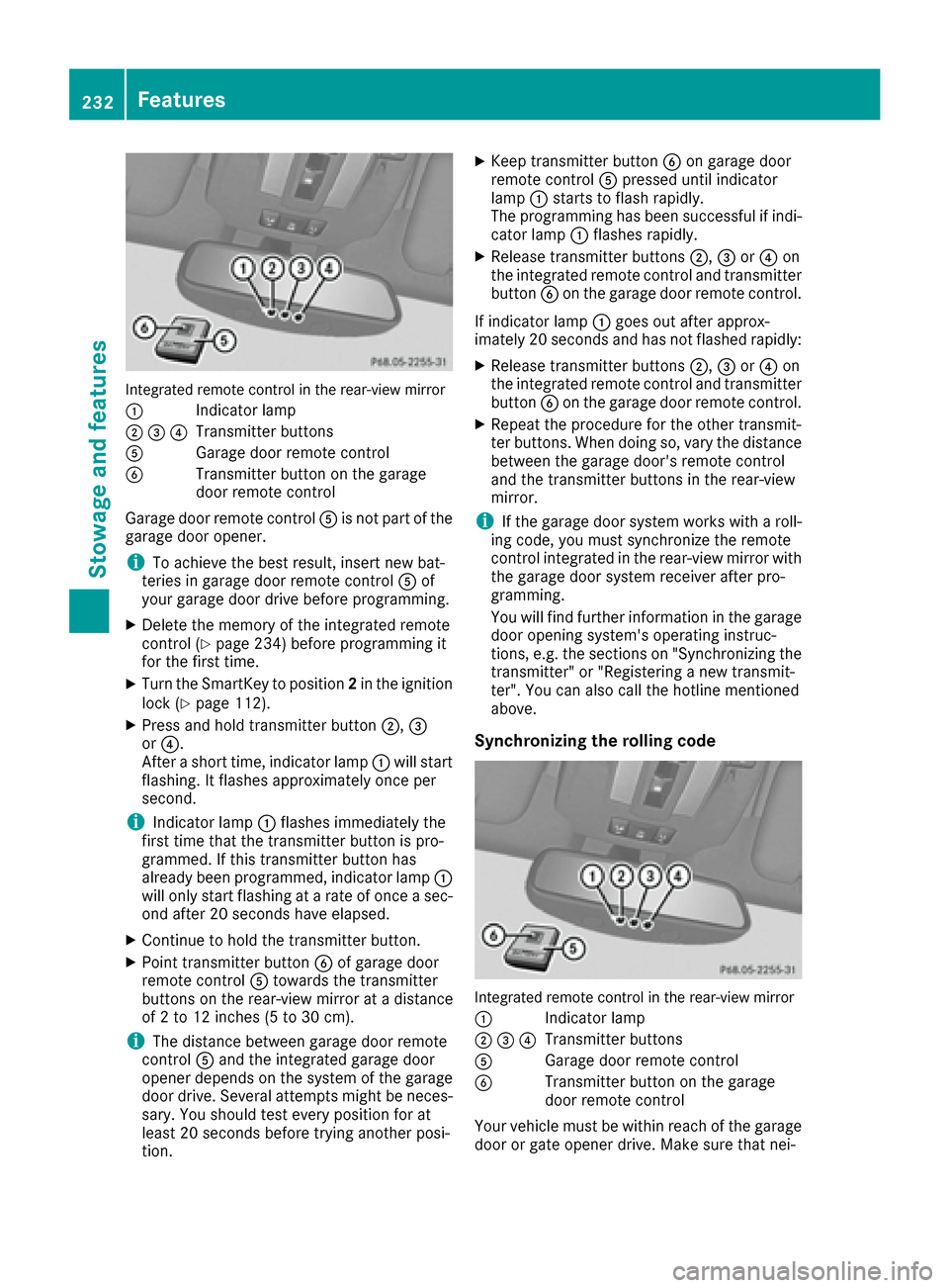
Integrated remote control in the rear-view mirror
:
Indicator lamp
;=?Transmitter buttons
AGarage door remote control
BTransmitter button on the garage
door remote control
Garage door remote control Ais not part of the
garage door opener.
iTo achieve the best result, insert new bat-
teries in garage door remote control Aof
your garage door drive before programming.
XDelete the memory of the integrated remote
control (Ypage 234) before programming it
for the first time.
XTurn the SmartKey to position 2in the ignition
lock (Ypage 112).
XPress and hold transmitter button ;,=
or ?.
After a short time, indicator lamp :will start
flashing. It flashes approximately once per
second.
iIndicator lamp :flashes immediately the
first time that the transmitter button is pro-
grammed. If this transmitter button has
already been programmed, indicator lamp :
will only start flashing at a rate of once a sec-
ond after 20 seconds have elapsed.
XContinue to hold the transmitter button.
XPoint transmitter button Bof garage door
remote control Atowards the transmitter
buttons on the rear-view mirror at a distance
of 2 to 12 inches (5 to 30 cm).
iThe distance between garage door remote
control Aand the integrated garage door
opener depends on the system of the garage
door drive. Several attempts might be neces-
sary. You should test every position for at
least 20 seconds before trying another posi-
tion.
XKeep transmitter button Bon garage door
remote control Apressed until indicator
lamp :starts to flash rapidly.
The programming has been successful if indi-
cator lamp :flashes rapidly.
XRelease transmitter buttons ;,=or? on
the integrated remote control and transmitter
button Bon the garage door remote control.
If indicator lamp :goes out after approx-
imately 20 seconds and has not flashed rapidly:
XRelease transmitter buttons ;,=or? on
the integrated remote control and transmitter button Bon the garage door remote control.
XRepeat the procedure for the other transmit-
ter buttons. When doing so, vary the distance
between the garage door's remote control
and the transmitter buttons in the rear-view
mirror.
iIf the garage door system works with a roll-
ing code, you must synchronize the remote
control integrated in the rear-view mirror with the garage door system receiver after pro-
gramming.
You will find further information in the garage
door opening system's operating instruc-
tions, e.g. the sections on "Synchronizing the
transmitter" or "Registering a new transmit-
ter". You can also call the hotline mentioned
above.
Synchronizing the rolling code
Integrated remote control in the rear-view mirror
:
Indicator lamp
;=?Transmitter buttons
AGarage door remote control
BTransmitter button on the garage
door remote control
Your vehicle must be within reach of the garage door or gate opener drive. Make sure that nei-
232Features
Stowage and features