2016 MERCEDES-BENZ G-Class ESP
[x] Cancel search: ESPPage 163 of 302

Problems with PARKTRONIC
ProblemPossible causes/consequences andMSolutions
Only the red segments in
the PARKTRONIC warn-
ing displays are lit. You
also hear a warning tone
for approximately two
seconds.
PARKTRONIC is deacti-
vated after a few sec-
onds, and the indicator
lamp in the PARKTRONIC
button lights up.PARKTRONIC has malfunctioned and has switched off.
XIf problems persist, have PARKTRONIC checked at a qualified spe-
cialist workshop.
Only the red segments in
the PARKTRONIC warn-
ing displays are lit.
PARKTRONIC is deacti-
vated after a few sec-
onds.The PARKTRONIC sensors are dirty or there is interference.
XClean the PARKTRONIC sensors (Ypage 244).
XSwitch the ignition back on.
The problem may be caused by an external source of radio or ultra-
sound waves.
XSee if PARKTRONIC functions in a different location.
Rear view camera
Important safety notes
The rear view camera is only an aid. It is not a
replacement for your attention to your immedi-
ate surroundings. You are always responsible
for safe maneuvering and parking. When maneu-
vering or parking, make sure that there are no
persons, animals or objects in the area in which
you are maneuvering.
Under the following circumstances, the rear
view camera will not function, or will function in
a limited manner:
Rthe rear door is open
Rin heavy rain, snow or fog
Rat night or in very dark places
Rif the camera is exposed to very bright light
Rif the area is lit by fluorescent light or LED
lighting (the display may flicker)
Rif there is a sudden change in temperature,
e.g. when driving into a heated garage in win- ter
Rif the camera lens is dirty or obstructed
Rif the rear of your vehicle is damaged. In this
event, have the camera position and setting
checked at a qualified specialist workshop Mercedes-Benz recommends that you use an
authorized Mercedes-Benz Center for this
purpose
Activating/deactivating the rear view
camera
:Rear view camera
Driving systems161
Driving and parking
Z
Page 164 of 302
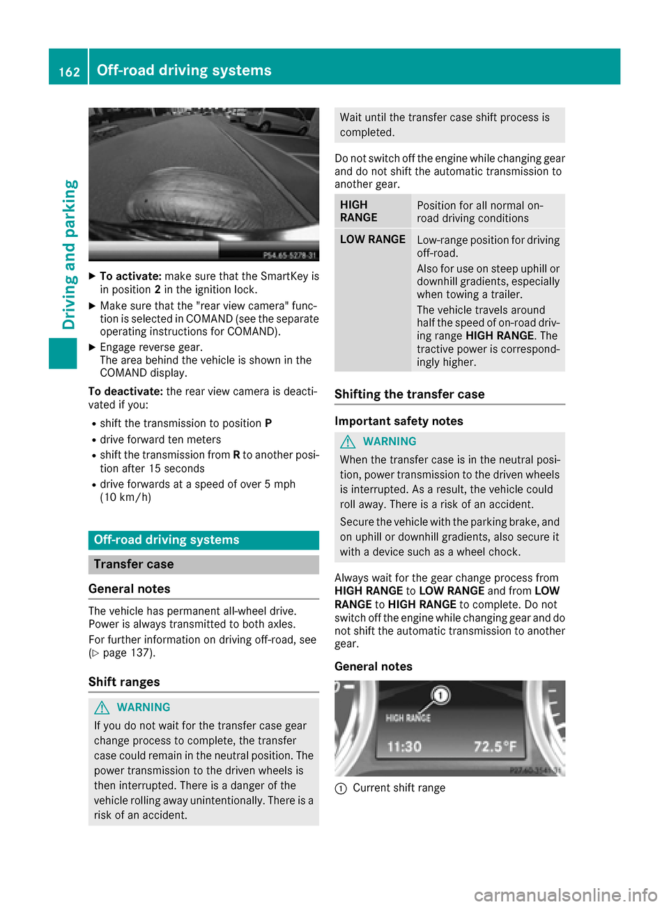
XTo activate:make sure that the SmartKey is
in position 2in the ignition lock.
XMake sure that the "rear view camera" func-
tion is selected in COMAND (see the separate
operating instructions for COMAND).
XEngage reverse gear.
The area behind the vehicle is shown in the
COMAND display.
To deactivate: the rear view camera is deacti-
vated if you:
Rshift the transmission to position P
Rdrive forward ten meters
Rshift the transmission fromRto another posi-
tion after 15 seconds
Rdrive forwards at a speed of over 5 mph
(10 km/h)
Off-road driving systems
Transfer case
General notes
The vehicle has permanent all-wheel drive.
Power is always transmitted to both axles.
For further information on driving off-road, see
(
Ypage 137).
Shift ranges
GWARNING
If you do not wait for the transfer case gear
change process to complete, the transfer
case could remain in the neutral position. The power transmission to the driven wheels is
then interrupted. There is a danger of the
vehicle rolling away unintentionally. There is a
risk of an accident.
Wait until the transfer case shift process is
completed.
Do not switch off the engine while changing gear
and do not shift the automatic transmission to
another gear.
HIGH
RANGEPosition for all normal on-
road driving conditions
LOW RANGELow-range position for driving
off-road.
Also for use on steep uphill or
downhill gradients, especially
when towing a trailer.
The vehicle travels around
half the speed of on-road driv-
ing range HIGH RANGE . The
tractive power is correspond-
ingly higher.
Shifting the transfer case
Important safety notes
GWARNING
When the transfer case is in the neutral posi-
tion, power transmission to the driven wheels
is interrupted. As a result, the vehicle could
roll away. There is a risk of an accident.
Secure the vehicle with the parking brake, and
on uphill or downhill gradients, also secure it
with a device such as a wheel chock.
Always wait for the gear change process from
HIGH RANGE toLOW RANGE and fromLOW
RANGE toHIGH RANGE to complete. Do not
switch off the engine while changing gear and do
not shift the automatic transmission to another
gear.
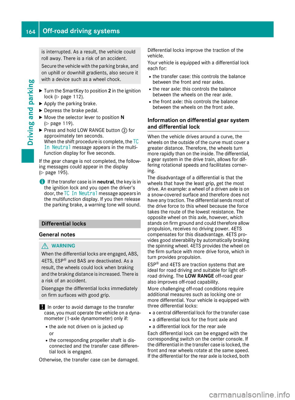
General notes
:Current shift range
162Off-road driving systems
Driving an d parking
Page 166 of 302
is interrupted. As a result, the vehicle could
roll away. There is a risk of an accident.
Secure the vehicle with the parking brake, and
on uphill or downhill gradients, also secure it
with a device such as a wheel chock.
XTurn the SmartKey to position2in the ignition
lock (Ypage 112).
XApply the parking brake.
XDepress the brake pedal.
XMove the selector lever to position N
(Ypage 119).
XPress and hold LOW RANGE button ;for
approximately ten seconds.
When the shift procedure is complete, the TC
In Neutralmessage appears in the multi-
function display for five seconds.
If the gear change is not completed, the follow-
ing messages could appear in the display
(
Ypage 195).
iIf the transfer case is in neutral, the key is in
the ignition lock and you open the driver's
door, the TC
InNeutralmessage appears in
the multifunction display. If you then release
the parking brake, a warning tone will sound.
Differential locks
General notes
GWARNING
When the differential locks are engaged, ABS, 4ETS, ESP
®and BAS are deactivated. As a
result, the wheels could lock when braking
and the braking distance is increased. There is
a risk of an accident.
Disengage the differential locks immediately
on firm surfaces with good grip.
!In order to avoid damage to the transfer
case, you must operate the vehicle on a dyna-
mometer (1-axle dynamometer) only if:
Rthe axle not driven on is jacked up
or
Rthe corresponding propeller shaft is dis-
connected and the transfer case differen-
tial lock is engaged.
Otherwise, the transfer case can be damaged. Differential locks improve the traction of the
vehicle.
Your vehicle is equipped with a differential lock
each for:
Rthe transfer case: this controls the balance
between the front and rear axles.
Rthe rear axle: this controls the balance
between the wheels on the rear axle.
Rthe front axle: this controls the balance
between the wheels on the front axle.
Information on differential gear system
and differential lock
When the vehicle drives around a curve, the
wheels on the outside of the curve must cover a
greater distance. Therefore, the wheels turn
more rapidly than on the inside. The differential,
a gear system in the drive train, allows for dif-
fering rotational speeds and facilitates corner-
ing.
The disadvantage of a differential is that the
wheels that have the least grip, get the most
drive. An example: a wheel of a driven axle is on
a snow-covered surface and therefore does not
have any traction. The differential sends most of
the drive force to this wheel because the force
takes the route of the lowest resistance. The
opposite wheel on this axle, however, which
stands on firm ground and could therefore allow
propulsion, receives no driving power. 4ETS
compensates for this disadvantage. 4ETS pro-
vides good steerability by automatically braking
the spinning wheel. 4ETS provides the wheel on
the firm surface with more drive force, which in
turn provides propulsion.
ESP
®and 4ETS are traction systems that are
ideal for road driving and suitable for light off-
road driving. The LOW RANGEoff-road gear
also improves off-road capability.
More challenging off-road conditions require
additional measures such as locking one or
more differential. Your vehicle is equipped with
three differential locks:
Ra central differential lock for the transfer case
Ra differential lock for the front axle and
Ra differential lock for the rear axle
Each differential lock can be engaged with the
corresponding switch on the center console. If
the differential in the transfer case is locked, the
front and rear wheels rotate at the same speed.
If t
he differential for the rear axle is locked, both
164Off-road driving systems
Driving and parking
Page 167 of 302
rear wheels rotate at the same speed, regard-
less of their respective torque. Note, engaging
the differential lock greatly impairs the vehicle's
steerability.
Note, it is imperative to use the differential func-
tion when driving on firm road surfaces. Under
no circumstances should the differential be
locked when driving on firm road surfaces. Oth-
erwise, the vehicle may not be steerable and you
could lose control of the vehicle. Therefore, only
engage the differential lock when driving off-
road. You should only engage the differential
lock if activating 4ETS and ESP
®driving systems
and LOW RANGE off-road gear prove to be
insufficient.
Engaging the differential locks
Important safety notes
GWARNING
When differential locks are engaged on a firm,
high-grip surface, the vehicle's steerability is
greatly impaired. In particular, engaging the
differential locks when cornering could lead
to you losing control of the vehicle. There is a risk of an accident.
Disengage the differential locks immediately
on firm surfaces with good grip.
GWARNING
When the differential locks are engaged, ABS, 4ETS, ESP
®and BAS are deactivated. As a
result, the wheels could lock when braking
and the braking distance is increased. There is
a risk of an accident.
Disengage the differential locks immediately
on firm surfaces with good grip.
!Only engage the differential locks when:
Ryou are driving at walking pace.
Rthe driven wheels are not spinning.
Ryou are not driving on a firm road surface.
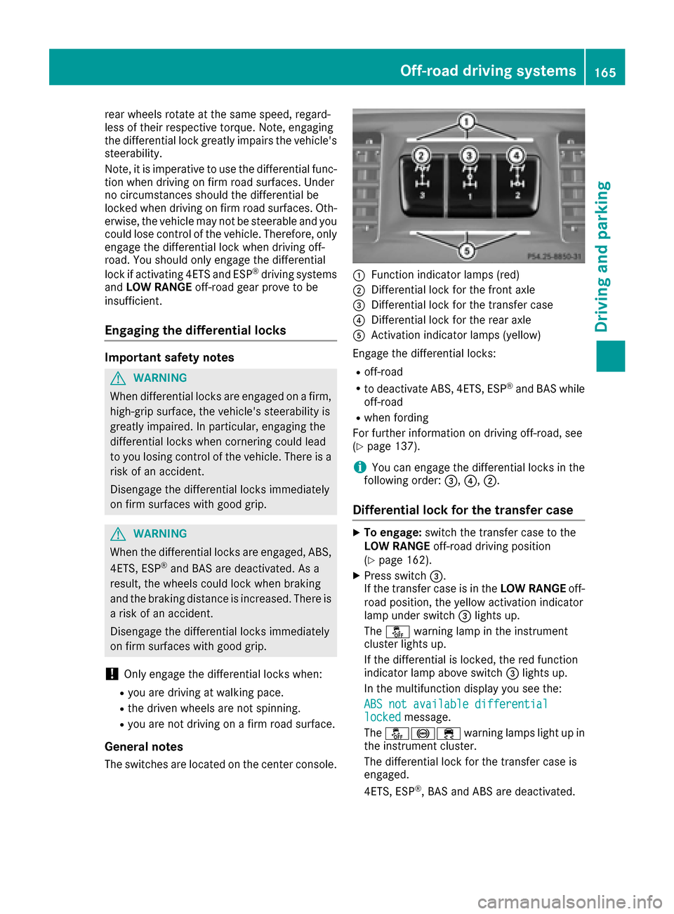
General notes
The switches are located on the center console.
:Function indicator lamps (red)
;Differential lock for the front axle
=Differential lock for the transfer case
?Differential lock for the rear axle
AActivation indicator lamps (yellow)
Engage the differential locks:
Roff-road
Rto deactivate ABS, 4ETS, ESP®and BAS while
off-road
Rwhen fording
For further information on driving off-road, see
(
Ypage 137).
iYou can engage the differential locks in the
following order: =,?,;.
Differential lock for the transfer case
XTo engage: switch the transfer case to the
LOW RANGE off-road driving position
(
Ypage 162).
XPress switch =.
If the transfer case is in the LOW RANGEoff-
road position, the yellow activation indicator
lamp under switch =lights up.
The å warning lamp in the instrument
cluster lights up.
If the differential is locked, the red function
indicator lamp above switch =lights up.
In the multifunction display you see the:
ABS not available differential
lockedmessage.
The å!÷ warning lamps light up in
the instrument cluster.
The differential lock for the transfer case is
engaged.
4ETS, ESP
®, BAS and ABS are deactivated.
Off-road driving systems165
Driving and parking
Z
Page 168 of 302
The vehicle's ability to steer is severely restric-
ted. Drive carefully and accelerate gently for
optimum traction.
iYou can now engage the differential lock for
rear axle ?and the differential lock for front
axle ;as required.
Differential lock for the rear axle
XTo engage: press switch ?.
Yellow activation indicator lamp Alights up
first, followed by red function indicator
lamp :of switch ?.
The differential lock for the rear axle is
engaged.
Differential lock for the front axle
XTo engage: press switch ;.
First, the yellow activation indicator lamp
lights up, followed by the red function indica-
tor lamp.
The differential lock for the front axle is
engaged.
Disengaging the differential locks
You can disengage the differential locks in the
following order: ;,?,=.
XTo simultaneously disengage all differen-
tial locks: press switch =.
Yellow activation indicator lamps Aand red
function indicator lamps :go out.
After approximately three seconds of normal
driving, ABS, 4ETS, ESP
®and BAS are activa-
ted.
The ABS not available differential
lockedmessage disappears in the multifunc-
tion display and the å,!and÷
warning lamps in the instrument cluster go
out.
XShift the transfer case to the HIGH RANGE
on-road position (Ypage 162).
iIf red function indicator lamps :do not go
out when disengaging the differential locks,
stop the vehicle safely as soon as possible, in
accordance with the traffic conditions. Then,
continue driving and the load change can
release the differential lock.
Towing a trailer
Notes on towing a trailer
Important safety notes
GWARNING
If you rest your foot on the brake pedal while
driving, the braking system can overheat. This increases the stopping distance and can even
cause the braking system to fail. There is a
risk of an accident.
Never use the brake pedal as a footrest. Never
depress the brake pedal and the accelerator
pedal at the same time.
GWARNING
When the vehicle/trailer combination begins
to lurch, you could lose control of it. The vehi- cle/trailer combination could even rollover.
There is a risk of an accident.
On no account should you attempt to
straighten up the vehicle/trailer combination
by increasing the speed. Reduce vehicle
speed and do not countersteer. Apply the
brake as necessary.
GWARNING
If you install a ball coupling other than the one
delivered with the vehicle, the trailer tow hitch
and the rear axle may be overloaded. This
applies especially if the ball coupling in ques-
tion is longer or angled differently. This could
seriously impair the driving characteristics
and the trailer can come loose. There is a risk
of an accident.
Only install the ball coupling delivered with
the vehicle or a ball coupling that is designed
to meet your trailer towing requirements. Do
not modify the ball coupling or the trailer tow
hitch.
GWARNING
If the ball coupling is not installed correctly or not secured with the bolt provided and the
corresponding spring cotter, the trailer may
come loose. There is a risk of an accident.
166Towing a trailer
Driving and parking
Page 169 of 302

Always install and secure the ball coupling asdescribed. Before every journey, ensure that
the ball coupling is secured with the bolt and
the corresponding spring cotter.
Please observe the manufacturer's operating
instructions for the trailer coupling if a detach-
able trailer coupling is used.
Exceeding the maximum permissible nose-
weight may cause damage to the following:
Ryour vehicle
Rthe trailer
Rthe ball coupling
Rtrailer tow hitch
The vehicle/trailer combination could become
unstable.
If the noseweight used is lower than the mini-
mum permissible noseweight, the vehicle/
trailer combination could also become unstable.
To avoid hazardous situations:
Rmake sure to check the noseweight before
each journey
Ruse a drawbar noseweight as close as possi-
ble to the maximum noseweight
Rdo not exceed the maximum permissible
noseweight
Rdo not use a noseweight lower than the min-
imum permissible trailer drawbar noseweight
When backing up the vehicle towards the trailer,
make sure there is nobody between the trailer
and the vehicle.
The applicable permissible values, which must
not be exceeded, can be fou nd:
Rin your vehicle documents
Ron the type plate of the trailer tow hitch and
trailer
Ron the vehicle identification plate
Couple and uncouple the trailer carefully. If you
do not couple the trailer to the towing vehicle
correctly, the trailer could become detached.
Make sure that the following values are not
exceeded:
Rthe permissible trailer drawbar noseweight
Rthe permissible trailer load
Rthe permissible rear axle load of the towing
vehicle
Rthe maximum permissible gross vehicle
weight of both the towing vehicle and the
trailer When towing a trailer, your vehicle's handling
characteristics will be different in comparison
with when driving without a trailer.
The vehicle/trailer combination:
Ris heavier
Ris restricted in its acceleration and gradient-
climbing capability
Rhas an increased braking distance
Ris affected more by strong crosswinds
Rdemands more sensitive steering
Rhas a larger turning radius
This could impair the handling characteristics.
Adapt your driving style accordingly. Maintain a
safe distance. Drive carefully.
When towing a trailer, always adjust your speed
to the current road and weather conditions. Do
not excee
d the maximum permissible speed for
your vehicle/trailer combination.
You will find the values approved by the manu-
facturer on the vehicle identification plates and
those for the towing vehicle in the "Technical
data" section (
Ypage 297).
General notes
RDo not exceed the legally prescribed maxi-
mum speed for vehicle/trailer combinations
in the relevant country.
This lowers the risk of an accident.
ROnly install an approved trailer coupling on
your vehicle.
Further information on availability and on
installation is available from any authorized
Mercedes-Benz Center.
RThe bumpers of your vehicle are not suitable
for installing detachable trailer couplings.
RDo not install hired trailer couplings or other
detachable trailer couplings on the bumpers
of your vehicle.
RIf you do not need the ball coupling, remove
the ball coupling from the ball coupling
recess. This reduces the risk of damage to the
ball coupling.
iCheck the tire pressures when towing a
trailer. You will find the values in the tire pres-
sure table in the fuel filler flap of the vehicle
(
Ypage 266).
You will find installation dimensions and loads
under "Technical data" (
Ypage 297).
Towing a trailer167
Driving an d parking
Z
Page 184 of 302
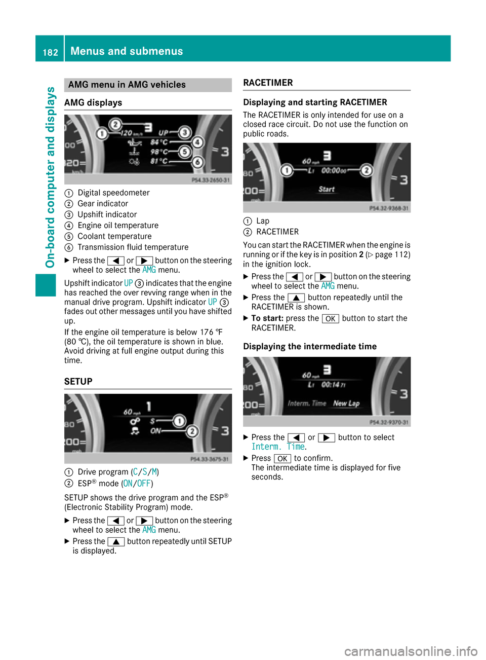
AMG menu in AMG vehicles
AMG displays
:Digital speedometer
;Gear indicator
=Upshif tindicator
?Engin eoil temperature
ACoolan ttemperature
BTransmission fluid temperature
XPress th e= or; buttonon th esteering
whee lto select th eAMGmenu.
Upshif tindicator UP
=indicates that th eengin e
has reached th eove rrevvin grange when in th e
manual drive program .Upshif tindicator UP
=
fade sout other message suntil you hav eshifte d
up.
If th eengin eoil temperature is belo w17 6 ‡
(80 †) ,the oi ltemper ature is shown in blue.
Avoid driving at full engine output during this
time.
SETUP
:Drive program (C/S/M)
;ESP®mode ( ON/OFF)
SETUP shows the drive program and the ESP
®
(Electronic Stability Program) mode.
XPress the =or; button on the steering
wheel to select the AMGmenu.
XPress the9button repeatedly until SETUP
is displayed.
RACETIMER
Displaying and starting RACETIMER
The RACETIMER is only intended for use on a
closed race circuit. Do not use the function on
public roads.
:Lap
;RACETIMER
You can start the RACETIMER when the engine is
running or if the key is in position 2(
Ypage 112)
in the ignition lock.
XPress the =or; button on the steering
wheel to select the AMGmenu.
XPress the9button repeatedly until the
RACETIMER is shown.
XTo start: press the abutton to start the
RACETIMER.
Displaying the intermediate time
XPress the =or; button to select
Interm. Time.
XPress ato confirm.
The intermediate time is displayed for five
seconds.
182Menus and submenus
On-board computer and displays
Page 186 of 302
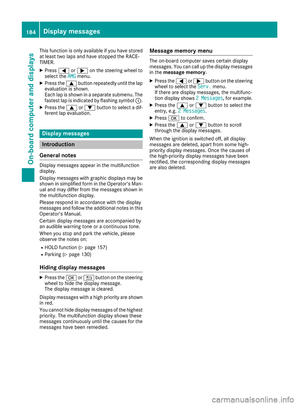
This function is only available if you have stored
at least two laps and have stopped the RACE-
TIMER.
XPress=or; on the steering wheel to
select the AMGmenu.
XPress the9button repeatedly until the lap
evaluation is shown.
Each lap is shown in a separate submenu. The
fastest lap is indicated by flashing symbol :.
XPress the9or: button to select a dif-
ferent lap evaluation.
Display messages
Introduction
General notes
Display messages appear in the multifunction
display.
Display messages with graphic displays may be
shown in simplified form in the Operator's Man-
ual and may differ from the messages shown in
the multifunction display.
Please respond in accordance with the display
messages and follow the additional notes in this Operator's Manual.
Certain display messages are accompanied by
an audible warning tone or a continuous tone.
When you stop and park the vehicle, please
observe the notes on:
RHOLD function (Ypage 157)
RParking (Ypage 130)
Hiding display messages
XPress the aor% button on the steering
wheel to hide the display message.
The display message is cleared.
Display messages with a high priority are shown
in red.
You cannot hide display messages of the highest
priority. The multifunction display shows these
messages continuously until the causes for the
messages have been remedied.
Message memory menu
The on-board computer saves certain display
messages. You can call up the display messages
in the message memory.
XPress the =or; button on the steering
wheel to select the Serv.menu.
If there are display messages, the multifunc-
tion display shows 2 Messages
, for example.
XPress the9or: button to select the
entry, e.g. 2 Messages.
XPressato confirm.
XPress the 9or: button to scroll
through the display messages.
When the ignition is switched off, all display
messages are deleted, apart from some high-
priority display messages. Once the causes of
the high-priority display messages have been
rectified, the corresponding display messages
are also deleted.
184Display messages
On-board computer and displays