Page 153 of 236
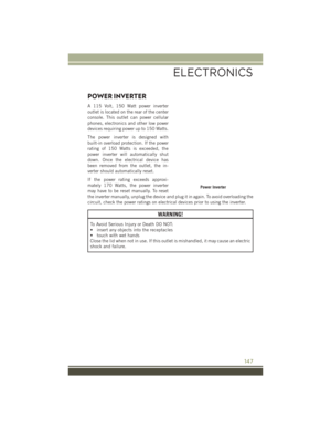
Wireless Charging Pad Operation
To use the wireless charging pad, the coil in your mobile phone needs to align with
the coil in the charging pad, which is located directly under the Qi logo. Since each
mobile phone’s coil location is different, you may need a few attempts to locate the
correct spot for your mobile phone:
1. Place your mobile phone on the wireless charging pad, towards the Qi logo, so thatthe LED turns red. If the LED does not turn red, pick up the mobile phone and
change it’s location.
NOTE:
The mobile phone mustbe aligned around
the Qi logo for the LED to transition from
red to flashing green.
2. Once the LED transitions from red to flashing green, your mobile phone is
correctly placed and charging.
3. If the LED does not transition from red to flashing green, and just turns off,
pick up your mobile phone and repo-
sition it on the charging pad.
Mobile Phone Alignment
ELECTRONICS
151
Page 154 of 236

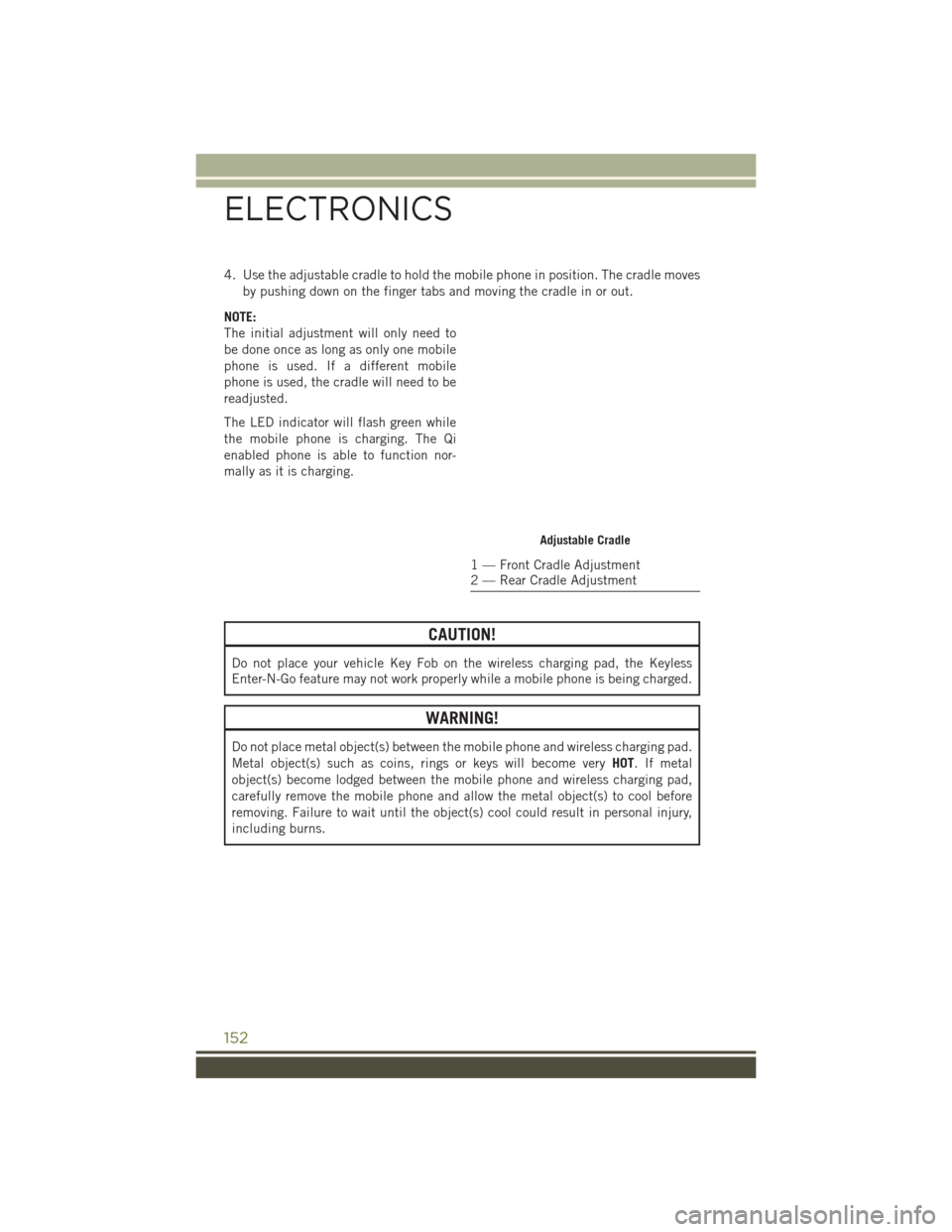
4. Use the adjustable cradle to hold the mobile phone in position. The cradle movesby pushing down on the finger tabs and moving the cradle in or out.
NOTE:
The initial adjustment will only need to
be done once as long as only one mobile
phone is used. If a different mobile
phone is used, the cradle will need to be
readjusted.
The LED indicator will flash green while
the mobile phone is charging. The Qi
enabled phone is able to function nor-
mally as it is charging.
CAUTION!
Do not place your vehicle Key Fob on the wireless charging pad, the Keyless
Enter-N-Go feature may not work properly while a mobile phone is being charged.
WARNING!
Do not place metal object(s) between the mobile phone and wireless charging pad.
Metal object(s) such as coins, rings or keys will become very HOT. If metal
object(s) become lodged between the mobile phone and wireless charging pad,
carefully remove the mobile phone and allow the metal object(s) to cool before
removing. Failure to wait until the object(s) cool could result in personal injury,
including burns.
Adjustable Cradle
1 — Front Cradle Adjustment
2 — Rear Cradle Adjustment
ELECTRONICS
152
Page 155 of 236
FOUR-WHEEL DRIVE OPERATION
1–SPEED FOUR-WHEEL DRIVE (4X4)
This feature provides on-demand Four-Wheel Drive (4X4) with no driver inputs or
additional driving skills required.
Under normal driving conditions, the front wheels provide most of the traction.
If the front wheels begin to lose traction,
power is shifted automatically to the rear
wheels.
NOTE:
On dry pavement under heavy throttle
input (where one may have wheel spin),
torque will be sent to the rear wheels to
improve vehicle launch and performance
characteristics.
2–SPEED FOUR-WHEEL DRIVE (4X4)
This electronically shifted Power Transfer Unit provides three mode positions:
• Four Wheel Drive High (4WD)
• Neutral (N)
• Four Wheel Drive Low (4WDLOW)
The 4X4 LOW range can be used when
additional traction is required to force the
front and rear wheels to rotate at the
same speed.
4X4 LOW is intended for loose, slippery
road surfaces only.
1-Speed 4X4 Switch
2-Speed 4X4 Switch
OFF-ROAD CAPABILITIES
153
Page 156 of 236

The NEUTRAL position allows vehicles with 2-speed Four-Wheel Drive to be flat
towed (with all wheels on the ground) without damaging the drivetrain. Refer to
“Recreational Towing” for instructions on shifting into and out of NEUTRAL.
NOTE:
In 4X4 LOW the engine speed is approximately three times that of the normal driving
mode at a given road speed. Take care not to overspeed the engine and do not exceed
25 mph (40 km/h).
Shifting Procedures
4X4 HI To 4X4 LOW
With the vehicle at speeds of 0 to 3 mph (0 to 5 km/h), the ignition switch in the ON
position or the engine running, shift the transmission into NEUTRAL, and press the
“4WD LOW” button once. The “4WD LOW” indicator light in the instrument cluster
will begin to flash and remain on solid when the shift is complete.
NOTE:
If shift conditions/interlocks are not met a message will flash from the Electronic
Vehicle Information Center (EVIC)/Driver Information Display (DID) with instructions
on how to complete the requested shift. Refer to “Electronic Vehicle Information
Center (EVIC)/Driver Information Display (DID)” in “Understanding Your Instrument
Panel” on the DVD for further information.
4X4 LOW To 4X4 HI
With the vehicle at speeds of 0 to 3 mph (0 to 5 km/h), the ignition switch in the ON
position or the engine running, shift the transmission into NEUTRAL, and press the
“4WD LOW” button once. The “4WD LOW” indicator light in the instrument cluster
will flash and go out when the shift is complete.
NOTE:
If shift conditions/interlocks are not met a message will flash from the Electronic
Vehicle Information Center (EVIC)/Driver Information Display (DID) with instructions
on how to complete the requested shift. Refer to “Electronic Vehicle Information
Center (EVIC)/Driver Information Display (DID)” in “Understanding Your Instrument
Panel” on the DVD for further information.
OFF-ROAD CAPABILITIES
154
Page 157 of 236

REAR ELECTRONIC LOCKER (E-LOCKER) SYSTEM
The Rear E-Locker System features a mechanical locking rear differential to provide
better traction in the 4WD LOW position. The “REAR LOCK” button is on the
Selec-Terrain Knob.
Activating The Rear E-Locker
To activate the Rear E-Locker System, the following conditions must be met:
• The 4WD system must be in 4WD LOW.
• The ignition switch in the ON position or the engine running.
• Vehicle speed must be below 15 MPH (24 km/h).
• To engage Rear E-Locker, push the REAR LOCK button once.
Deactivating The Rear E-Locker System
To deactivate the Rear E-Locker System, the following conditions must be met:
• Rear E-Locker must be engaged, and the REAR LOCK indicator light on.
• The ignition switch in the ON position or the engine running.
• To disengage Rear E-Locker , push the REAR LOCK button once.
NOTE:
• It may also be necessary to drive slowly steering back and forth to completeengagement and disengagement of the E- Locker.
• When engaging Rear E-Locker, the indicator lights in the instrument cluster and on the REAR LOCK button will begin to flash. When the shift is complete the REAR
LOCK indicator lights will remain on.
• When disengaging Rear E-Locker, the indicator lights in the instrument cluster and on the REAR LOCK button will begin to flash. When the shift is complete the
REAR LOCK indicator lights will remain off.
• Shifting into or out of Rear E-Locker is possible with the vehicle completely stopped; however, difficulty may occur due to the mating clutch teeth not being
properly aligned. Several attempts may be required for clutch teeth alignment and
shift completion to occur. The preferred method is for the vehicle to be rolling,
below 15 MPH (24 km/h), while including right and left steering maneuvers to
allow for the clutch teeth to align.
• The Rear E-Locker System must be disengaged prior to taking the vehicle out of 4X4 LOW range. If 4X4 LOW shift conditions/interlocks are not met, a message will
flash from the Electronic Vehicle Information Center (EVIC)/Driver Information
Display with instructions on how to complete the requested shift.
OFF-ROAD CAPABILITIES
155
Page 158 of 236

SELEC-TERRAIN
Selec-Terrain combines the capabilities of the vehicle control systems, along with
driver input, to provide the best performance for all terrains.
Rotate the mode control knob to select
the following Selec-Terrain positions:
•Auto — Fully automatic full time four-
wheel drive operation can be used on
and off road. Balances traction with
seamless steering feel to provide im-
proved handling and acceleration over
two-wheel drive vehicles.
• Snow — Tuning set for additional sta-
bility in inclement weather. Use on and
off road on loose traction surfaces such
as snow. When in SNOW mode (de-
pending on certain operating condi-
tions), the transmission may use sec-
ond gear (rather than first gear) during
launches, to minimize wheel slippage.
• Sport — This mode alters the transmission's automatic shift schedule for sportier
driving. Upshift speeds are increased to make full use of available engine power.
• Sand/Mud — Off road calibration for use on low traction surfaces such as mud,
sand, or wet grass. Driveline is maximized for traction. Some binding may be felt
on less forgiving surfaces. The electronic brake controls are set to limit traction
control management of throttle and wheel spin.
• Rock — Off-road calibration only available in 4WD LOW range. Traction based
tuning with improved steer-ability for use on high traction off-road surfaces.
Activate the Hill Descent Control for steep downhill control. Use for low speed
obstacles such as large rocks, deep ruts, etc.
NOTE:
SPORT mode is not available when 4X4 LOW is selected.
Selec-Terrain Switch
OFF-ROAD CAPABILITIES
156
Page 159 of 236

CARGO AREA FEATURES
Cargo Load Floor
The cargo load floor system has a load capacity of 400 lbs (181 kg).
To provide additional storage area, each rear seat can be folded flat. This allows for
extended cargo space and still maintains some rear seating room. Refer to “Rear
Seats” in “Getting Started” for further information.
Cargo Extension Panels
Cargo extension panels can be folded and unfolded. When the rear seats are moved
to the more forward positions and the rear seat backs are folded down, the extension
panels can be unfolded manually by hand (2 of them). The extension panels can be
used to extend the load floor to the rear seats and/or hide the gap between the load
floor and rear seats, or to assist in loading large items into the cargo area.
Cargo Tie-Down Hooks And Loops
The tie-downs located on the cargo area floor should be used to secure loads safely
when the vehicle is moving.
Cargo tie-down loops are located on the trim panels.
WARNING!
• Cargo tie-downs are not safe anchors for a child seat tether strap. In a suddenstop or accident, a tie-down could pull loose and allow the child seat to come
loose. A child could be badly injured. Use only the anchors provided for child
seat tethers.
• To help protect against personal injury, passengers should not be seated in the
rear cargo area. The rear cargo space is intended for load carrying purposes
only, not for passengers, who should sit in seats and use seat belts.
WARNING!
The weight and position of cargo and passengers can change the vehicle center of
gravity and vehicle handling. To avoid loss of control resulting in personal injury,
follow these guidelines for loading your vehicle:
• Do not carry loads that exceed the load limits described on the label attachedto the left door or left door center pillar.
• Always place cargo evenly on the cargo floor. Put heavier objects as low and as
far forward as possible.
•
Place as much cargo as possible in front of the rear axle. Too much weight or
improperly placed weight over or behind the rear axle can cause the vehicle to sway.
•Do not pile luggage or cargo higher than the top of the seatback. This could impair
visibility or become a dangerous projectile in a sudden stop or accident.
UTILITY
157
Page 160 of 236

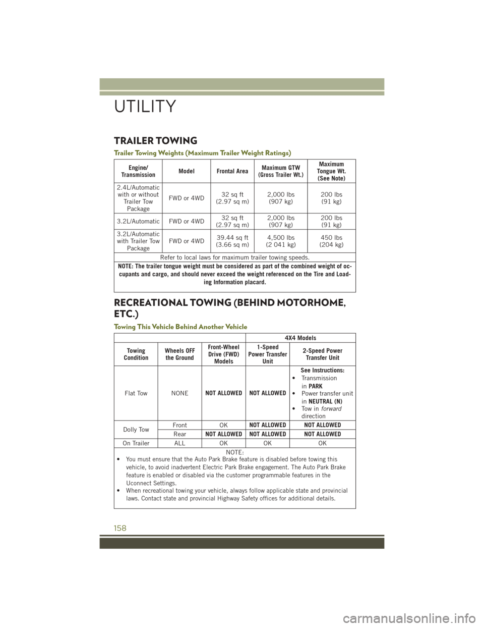
TRAILER TOWING
Trailer Towing Weights (Maximum Trailer Weight Ratings)
Engine/
Transmission Model Frontal Area Maximum GTW(Gross Trailer Wt.)
Maximum
Tongue Wt. (See Note)
2.4L/Automatic with or without Trailer TowPackage FWD or 4WD
32 sq ft
(2.97 sq m) 2,000 lbs
(907 kg) 200 lbs
(91 kg)
3.2L/Automatic FWD or 4WD 32 sq ft
(2.97 sq m) 2,000 lbs
(907 kg) 200 lbs
(91 kg)
3.2L/Automatic with Trailer Tow Package FWD or 4WD
39.44 sq ft
(3.66 sq m) 4,500 lbs
(2 041 kg) 450 lbs
(204 kg)
Refer to local laws for maximum trailer towing speeds.
NOTE: The trailer tongue weight must be considered as part of the combined weight of oc- cupants and cargo, and should never exceed the weight referenced on the Tire and Load- ing Information placard.
RECREATIONAL TOWING (BEHIND MOTORHOME,
ETC.)
Towing This Vehicle Behind Another Vehicle
4X4 Models
Towing
Condition Wheels OFF
the Ground Front-Wheel
Drive (FWD) Models 1-Speed
Power Transfer Unit 2-Speed Power
Transfer Unit
Flat Tow NONE NOT ALLOWED NOT ALLOWED See Instructions:
• Transmission
inPARK
• Power transfer unit
inNEUTRAL (N)
• Tow in forward
direction
Dolly Tow Front OK
NOT ALLOWED NOT ALLOWED
Rear NOT ALLOWED NOT ALLOWED NOT ALLOWED
On Trailer ALL OK OK OK NOTE:
•
You must ensure that the Auto Park Brake feature is disabled before towing this
vehicle, to avoid inadvertent Electric Park Brake engagement. The Auto Park Brake
feature is enabled or disabled via the customer programmable features in the
Uconnect Settings.
•When recreational towing your vehicle, always follow applicable state and provincial
laws. Contact state and provincial Highway Safety offices for additional details.
UTILITY
158