2016 FIAT TIPO 5DOORS STATION WAGON warning
[x] Cancel search: warningPage 128 of 240
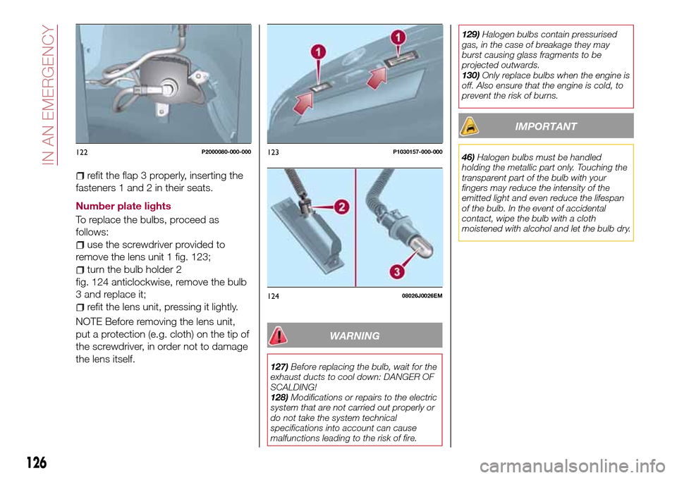
refit the flap 3 properly, inserting the
fasteners 1 and 2 in their seats.
Number plate lights
To replace the bulbs, proceed as
follows:
use the screwdriver provided to
remove the lens unit 1 fig. 123;
turn the bulb holder 2
fig. 124 anticlockwise, remove the bulb
3 and replace it;
refit the lens unit, pressing it lightly.
NOTE Before removing the lens unit,
put a protection (e.g. cloth) on the tip of
the screwdriver, in order not to damage
the lens itself.
WARNING
127)Before replacing the bulb, wait for the
exhaust ducts to cool down: DANGER OF
SCALDING!
128)Modifications or repairs to the electric
system that are not carried out properly or
do not take the system technical
specifications into account can cause
malfunctions leading to the risk of fire.129)Halogen bulbs contain pressurised
gas, in the case of breakage they may
burst causing glass fragments to be
projected outwards.
130)Only replace bulbs when the engine is
off. Also ensure that the engine is cold, to
prevent the risk of burns.
IMPORTANT
46)Halogen bulbs must be handled
holding the metallic part only. Touching the
transparent part of the bulb with your
fingers may reduce the intensity of the
emitted light and even reduce the lifespan
of the bulb. In the event of accidental
contact, wipe the bulb with a cloth
moistened with alcohol and let the bulb dry.122P2000080-000-000123P1030157-000-000
12408026J0026EM
126
IN AN EMERGENCY
Page 134 of 240
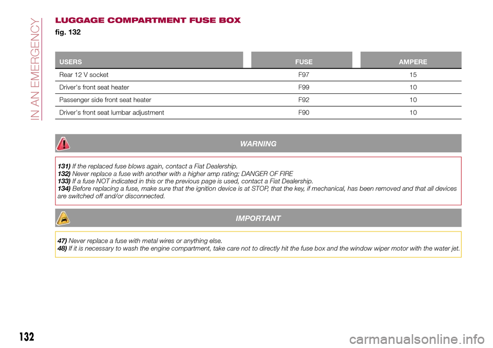
LUGGAGE COMPARTMENT FUSE BOX
fig. 132
USERSFUSE AMPERE
Rear 12 V socket F97 15
Driver's front seat heater F99 10
Passenger side front seat heater F92 10
Driver's front seat lumbar adjustment F90 10
WARNING
131)If the replaced fuse blows again, contact a Fiat Dealership.
132)Never replace a fuse with another with a higher amp rating; DANGER OF FIRE
133)If a fuse NOT indicated in this or the previous page is used, contact a Fiat Dealership.
134)Before replacing a fuse, make sure that the ignition device is at STOP, that the key, if mechanical, has been removed and that all devices
are switched off and/or disconnected.
IMPORTANT
47)Never replace a fuse with metal wires or anything else.
48)If it is necessary to wash the engine compartment, take care not to directly hit the fuse box and the window wiper motor with the water jet.
132
IN AN EMERGENCY
Page 135 of 240
CHANGING A WHEEL
JACK
Please note that:
the jack weight is 2.15 kg;
the jack cannot be repaired and in
the event of a fault it must be replaced
by another genuine one;
No tool other than its cranking device
may be fitted on the jack.
Servicing
Prevent any dirt from depositing on
the "worm screw";
Keep the "worm screw" lubricated;
Never modify the jack.
Conditions for non-use
Temperatures below −40°C;
On sandy or muddy ground;
On uneven ground;
On steep roads;
In extreme weather conditions:
thunderstorms, typhoons, hurricanes,
blizzards, storms, etc.
In direct contact with the engine or
for repairs under the vehicle;
On boats.
CHANGING PROCEDURE
135) 136) 137) 138) 139)
49) 50)
Proceed as follows:
stop the car in a position that is not
dangerous for oncoming traffic where
you can change the wheel safely. The
ground must be flat and sufficiently
compact;
stop the engine, engage the hazard
warning lights and the parking brake;
engage first gear or reverse;
wear the reflective safety jacket
before getting out of the car (anyway
comply with the laws in force in the
country you are driving in);
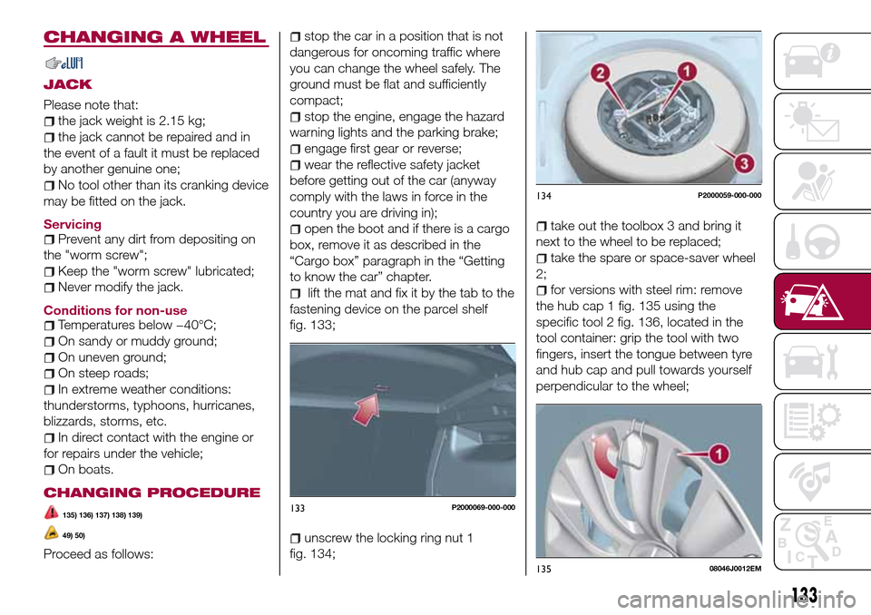
open the boot and if there is a cargo
box, remove it as described in the
“Cargo box” paragraph in the “Getting
to know the car” chapter.
lift the mat and fix it by the tab to the
fastening device on the parcel shelf
fig. 133;
unscrew the locking ring nut 1
fig. 134;
take out the toolbox 3 and bring it
next to the wheel to be replaced;
take the spare or space-saver wheel
2;
for versions with steel rim: remove
the hub cap 1 fig. 135 using the
specific tool 2 fig. 136, located in the
tool container: grip the tool with two
fingers, insert the tongue between tyre
and hub cap and pull towards yourself
perpendicular to the wheel;
133P2000069-000-000
134P2000059-000-000
13508046J0012EM
133
Page 137 of 240
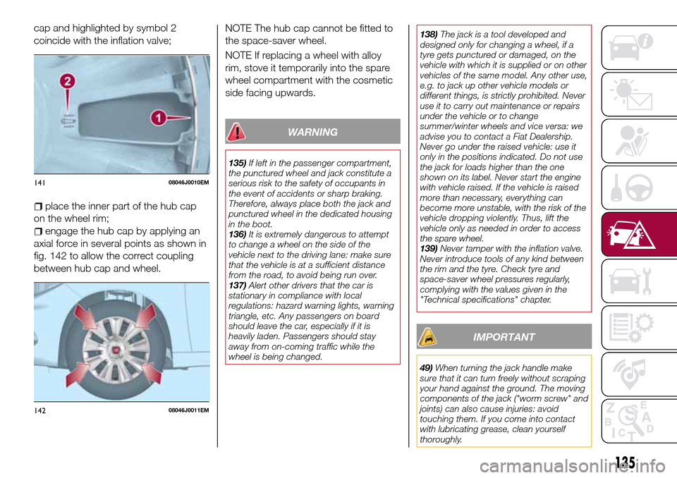
cap and highlighted by symbol 2
coincide with the inflation valve;
place the inner part of the hub cap
on the wheel rim;
engage the hub cap by applying an
axial force in several points as shown in
fig. 142 to allow the correct coupling
between hub cap and wheel.NOTE The hub cap cannot be fitted to
the space-saver wheel.
NOTE If replacing a wheel with alloy
rim, stove it temporarily into the spare
wheel compartment with the cosmetic
side facing upwards.
WARNING
135)If left in the passenger compartment,
the punctured wheel and jack constitute a
serious risk to the safety of occupants in
the event of accidents or sharp braking.
Therefore, always place both the jack and
punctured wheel in the dedicated housing
in the boot.
136)It is extremely dangerous to attempt
to change a wheel on the side of the
vehicle next to the driving lane: make sure
that the vehicle is at a sufficient distance
from the road, to avoid being run over.
137)Alert other drivers that the car is
stationary in compliance with local
regulations: hazard warning lights, warning
triangle, etc. Any passengers on board
should leave the car, especially if it is
heavily laden. Passengers should stay
away from on-coming traffic while the
wheel is being changed.138)The jack is a tool developed and
designed only for changing a wheel, if a
tyre gets punctured or damaged, on the
vehicle with which it is supplied or on other
vehicles of the same model. Any other use,
e.g. to jack up other vehicle models or
different things, is strictly prohibited. Never
use it to carry out maintenance or repairs
under the vehicle or to change
summer/winter wheels and vice versa: we
advise you to contact a Fiat Dealership.
Never go under the raised vehicle: use it
only in the positions indicated. Do not use
the jack for loads higher than the one
shown on its label. Never start the engine
with vehicle raised. If the vehicle is raised
more than necessary, everything can
become more unstable, with the risk of the
vehicle dropping violently. Thus, lift the
vehicle only as needed in order to access
the spare wheel.
139)Never tamper with the inflation valve.
Never introduce tools of any kind between
the rim and the tyre. Check tyre and
space-saver wheel pressures regularly,
complying with the values given in the
"Technical specifications" chapter.
IMPORTANT
49)When turning the jack handle make
sure that it can turn freely without scraping
your hand against the ground. The moving
components of the jack ("worm screw" and
joints) can also cause injuries: avoid
touching them. If you come into contact
with lubricating grease, clean yourself
thoroughly.
14108046J0010EM
14208046J0011EM
135
Page 140 of 240
if the pressure indicated is equal to or
higher than 1.8 bar / 26 psi, switch on
the compressor and reach the required
pressure. Disconnect and replace the
kit in the specific compartment.
Carefully drive and reach the Fiat
Dealership as soon as possible;
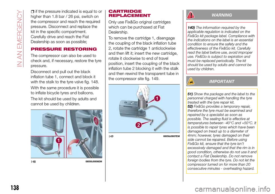
PRESSURE RESTORING
The compressor can also be used to
check and, if necessary, restore the tyre
pressure.
Disconnect and pull out the black
inflation tube 1, connect and block it
with the stalk to the tyre valve fig. 148.
With the same procedure it is possible
to inflate bicycle tyres and balloons.
The kit should be used by adults and
cannot be used by children.
CARTRIDGE
REPLACEMENT
Only use Fix&Go original cartridges
which can be purchased at Fiat
Dealership.
To remove the cartridge 1, disengage
the coupling of the black inflation tube
2, rotate the cartridge 1 anticlockwise
and then lift it; insert the new cartridge,
rotate it clockwise to end of travel
position, insert the coupling of the black
inflation tube 2 blocking it with the stalk
and then rewind the transparent tube in
the compressor site fig. 149.
WARNING
140)The information required by the
applicable regulation is indicated on the
Fix&Go kit package label. Compliance with
the indications on the label is an essential
condition to ensure the safety and the
effectiveness of the Fix&Go kit. Carefully
read the label before use, avoid improper
use. Fix&Go is subject to expiration and
must be replaced periodically. The kit
should be used by adults and cannot be
used by children.
IMPORTANT
51)Show the package and the label to the
personnel charged with handling the tyre
treated with the tyre repair kit.
52)Fix&Go provides a temporary repair,
therefore the tyre must be examined and
repaired by a specialist as soon as
possible. The sealing fluid is effective at
temperatures between -40°C and +50°C. It
is possible to repair tyres which have been
damaged on tread up to a diameter of
4mm; however, tyres damaged on their
side cannot be repaired. Before using
Fix&Go kit, ensure that the tyre isn't
excessively damaged and that the rim is in
good condition, otherwise do not use it and
contact a Fiat Dealership. Do not remove
foreign bodies from the tyre. Do not let the
compressor turned on for more than 20
consecutive minutes - overheating hazard.
14808056J0006EM
14908056J0007EM
138
IN AN EMERGENCY
Page 142 of 240
WARNING
141)Before opening the bonnet, make
sure that the engine is off and that the
ignition key is in the STOP position. Follow
the indications on the plate underneath the
bonnet. We recommend that you remove
the key from the ignition if other people
remain in the vehicle. The vehicle should
always be left after the key has been
removed or turned to the STOP position.
During refuelling, make sure that the engine
is off (and that the ignition key is in the
STOP position).
142)Do not get too close to the radiator
cooling fan: the electric fan may start;
danger of injury. Scarves, ties and other
loose clothing might be pulled by moving
parts.
143)Remove any metal objects (e.g. rings,
watches, bracelets), that might cause an
accidental electrical contact and cause
serious injury.
144)The batteries contain acid that can
burn skin or eyes. Batteries produce
hydrogen, which is easily flammable and
explosive. Therefore, keep away flames or
devices which may cause sparks.
IMPORTANT
53)Never use a fast battery-charger to
start the engine as this could damage the
electronic systems of your vehicle,
particularly the ignition and engine fuel
supply control units.54)Do not connect the cable to the
negative terminal (–) of the flat battery. The
following spark could lead to battery
explosion and cause serious harm. Only
use the specific earth point; do not use any
other exposed metallic part.
FUEL CUT-OFF
SYSTEM
DESCRIPTION
This intervenes in the case of an impact
causing:
the interruption of the fuel supply
with the engine consequently switching
off;
the automatic unlocking of the
doors;
turning on of the lights inside the
vehicle;
deactivation of climate control
system ventilation;
switching on of the hazard warning
lights (to deactivate the lights press the
button on the dashboard).
On some versions, the intervention of
the system is indicated by a message
shown on the display. In the same way,
a dedicated message on the display
warns the driver if system operation is
compromised.
IMPORTANT Carefully check the vehicle
for fuel leaks, for instance in the engine
compartment, under the vehicle or near
the tank area. After a collision, bring the
ignition device to STOP to prevent the
battery from running down.
140
IN AN EMERGENCY
Page 143 of 240
FUEL CUT-OFF SYSTEM RESET
To restore correct operation of the vehicle, carry out the following procedure (this procedure must be started and completed
within less than 1 minute):
145)
Operations to be carried out Display
With direction indicator lever in neutral position, bring the ignition
device to STOP
Bring the ignition device to MAR Right direction indicator flashing
Activate the right direction indicator Left direction indicator flashing; right direction indicator on constantly
Activate the left direction indicator Right direction indicator flashing; left direction indicator on constantly
Activate the right direction indicator Left direction indicator flashing; right direction indicator on constantly
Activate the left direction indicator Both direction indicators stay on constantly
Deactivate the left direction indicator Both direction indicators switch off
Bring the ignition device to STOP
Bring the ignition device to MAR The system has been reset and the engine can be restarted
WARNING
145)If, after an impact, you smell fuel or notice leaks from the fuel system, do not reactivate the system to avoid the risk of fire.
141
Page 144 of 240
TOWING THE
VEHICLE
ATTACHING THE TOW
RING
146) 147) 148)
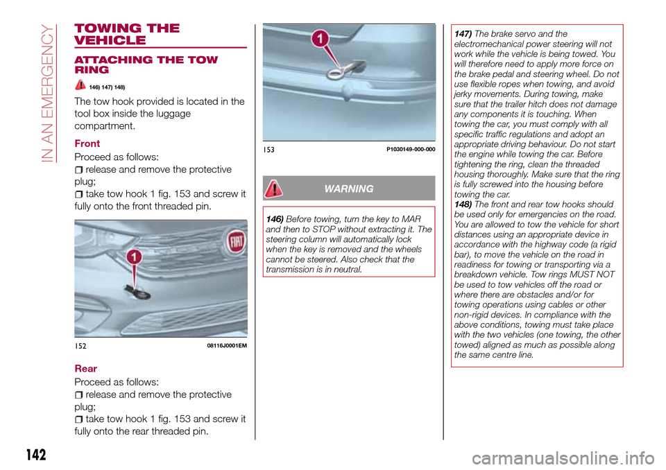
The tow hook provided is located in the
tool box inside the luggage
compartment.
Front
Proceed as follows:
release and remove the protective
plug;
take tow hook 1 fig. 153 and screw it
fully onto the front threaded pin.
Rear
Proceed as follows:
release and remove the protective
plug;
take tow hook 1 fig. 153 and screw it
fully onto the rear threaded pin.
WARNING
146)Before towing, turn the key to MAR
and then to STOP without extracting it. The
steering column will automatically lock
when the key is removed and the wheels
cannot be steered. Also check that the
transmission is in neutral.147)The brake servo and the
electromechanical power steering will not
work while the vehicle is being towed. You
will therefore need to apply more force on
the brake pedal and steering wheel. Do not
use flexible ropes when towing, and avoid
jerky movements. During towing, make
sure that the trailer hitch does not damage
any components it is touching. When
towing the car, you must comply with all
specific traffic regulations and adopt an
appropriate driving behaviour. Do not start
the engine while towing the car. Before
tightening the ring, clean the threaded
housing thoroughly. Make sure that the ring
is fully screwed into the housing before
towing the car.
148)The front and rear tow hooks should
be used only for emergencies on the road.
You are allowed to tow the vehicle for short
distances using an appropriate device in
accordance with the highway code (a rigid
bar), to move the vehicle on the road in
readiness for towing or transporting via a
breakdown vehicle. Tow rings MUST NOT
be used to tow vehicles off the road or
where there are obstacles and/or for
towing operations using cables or other
non-rigid devices. In compliance with the
above conditions, towing must take place
with the two vehicles (one towing, the other
towed) aligned as much as possible along
the same centre line.
15208116J0001EM
153P1030149-000-000
142
IN AN EMERGENCY