Page 342 of 587
 in exhaust gases is deadly.
Follow the precautions below to prevent carbon
monoxide poisoning:
•Do not inhale exhaust gases. They contain carbo")
Carbon Monoxide Warnings
WARNING!
Carbon monoxide (CO) in exhaust gases is deadly.
Follow the precautions below to prevent carbon
monoxide poisoning:
•Do not inhale exhaust gases. They contain carbon
monoxide, a colorless and odorless gas, which can
kill. Never run the engine in a closed area, such as
a garage, and never sit in a parked vehicle with the
engine running for an extended period. If the
vehicle is stopped in an open area with the engine
running for more than a short period, adjust the
ventilation system to force fresh, outside air into
the vehicle.
• Guard against carbon monoxide with proper main-
tenance. Have the exhaust system inspected every
(Continued)
WARNING! (Continued)
time the vehicle is raised. Have any abnormal
conditions repaired promptly. Until repaired, drive
with all side windows fully open.
ADDING FUEL
The Capless Fuel System uses a flapper placed at the filler
pipe of the fuel tank; it opens and closes automatically
upon insertion/extraction of the fuel nozzle.
The Capless Fuel System is designed so that it prevents
the filling of an incorrect type of fuel.
Opening The Door
For filling proceed as follows:
1. Open the door, by pushing and releasing on the
indentation point indicated by the arrow.
340 STARTING AND OPERATING
Page 353 of 587
RECREATIONAL TOWING (BEHIND MOTORHOME, ETC.)
Towing This Vehicle Behind Another Vehicle
FRONT WHEEL DRIVE (FWD)ALL-WHEEL
DRIVE (AWD)
TOWING
CONDITION WHEELS OFF THE
GROUND AUTOMATIC
TRANSMISSION MANUAL
TRANSMISSION MANUAL/
AUTOMATIC
TRANSMISSION
Flat Tow NONE NOT ALLOWED NOT ALLOWED NOT ALLOWED
Dolly Tow REARNOT ALLOWED NOT ALLOWED NOT ALLOWED
FRONT OKOKNOT ALLOWED
On Trailer ALLBEST METHOD BEST METHOD OK
NOTE: When recreationally towing your vehicle, always follow applicable state and provincial laws. Contact
state and provincial Highway Safety offices for additional details.
7
STARTING AND OPERATING 351
Page 384 of 587
Cavity Maxi FuseCartage FuseMini FuseDescription
F01 70 Amp Tan ––Module Body Com-
puter
F02 60 Amp Blue ––Module Body Com-
puter, Rear Distribution
Units
F03 – 20 Amp Blue–Controller Power Sup-
ply Body Computer
F04 – 30 Amp Pink–Brake Control Electron-
ics Module
F05 70 Amp Tan ––Electric Power-Assisted
Steering
F06 20 Amp Yellow – –Engine Cooling fan
F07 50 Amp Red ––Engine Cooling fan
F08 – 30 Amp Pink–Automatic Transmis-
sion, GSM
F09 – –5 Amp TanControl Module Engine
382 IN CASE OF EMERGENCY
Page 385 of 587
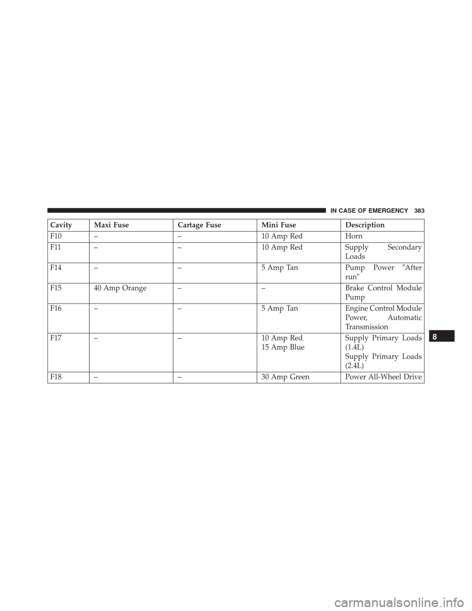
Cavity Maxi FuseCartage FuseMini FuseDescription
F10 – –10 Amp RedHorn
F11 – –10 Amp RedSupply Secondary
Loads
F14 – –5 Amp TanPump Power�After
run �
F15 40 Amp Orange – –Brake Control Module
Pump
F16 – –5 Amp TanEngine Control Module
Power, Automatic
Transmission
F17 – –10 Amp Red
15 Amp Blue Supply Primary Loads
(1.4L)
Supply Primary Loads
(2.4L)
F18 – –30 Amp Green Power All-Wheel Drive
8
IN CASE OF EMERGENCY 383
Page 386 of 587
Cavity Maxi FuseCartage FuseMini FuseDescription
F19 – –7.5 Amp Brown Air Conditioner Com-
pressor
F20 – –5 Amp TanElectronic Power Four-
Wheel Drive
F21 – –15 Amp BlueFuel Pump
F22 – –20 Amp Yelow Power Control Module
Engine
F23 – –20 Amp Yellow (Cus-
tomer Installed) Power Outlet (Battery
Powered)
F24 – –15 Amp BlueElectronic Unit Supply
Automatic Transmis-
sion
F30 – –30 Amp Green Heated Windshield – If
Equipped
F83 – 40 Amp Green – Air Conditioning Fan
384 IN CASE OF EMERGENCY
Page 387 of 587
Cavity Maxi FuseCartage FuseMini FuseDescription
F84 – –20 Amp Yellow Power Outlet (Ignition
Powered)
F87 – –5 Amp TanShift Lever Automatic
Transmission
F88 – –7.5 Amp Brown Heated Outside Mir-
rors
F89 – 30 Amp Pink–Heated Rear Window
F90 – –5 Amp TanIBS Sensor (Battery
State of Charge)
Body Computer Fuse Center
The controller is located at the left side of the steering
column at the bottom of the instrument panel.8
IN CASE OF EMERGENCY 385
Page 390 of 587
F51 7.5 Amp Brown Air Conditioning Compressor, Plaque Automatic Transmission, Rear Camera,Air Conditioning, LDW - Lane Departure Warning, ASS - Auxiliary Stack
Switch, DSU - Drive Syle Selector Unit, Reverse gear switch, side mirrors and
rear window defrost
F53 7.5 Amp Brown Supply IPC/Starter Device/System Keyless Enter-N-Go, Brake Pedal Switch (NA), EPB - Electric Parking Brake
Rear Cargo Fuse/Relay Distribution Unit
To access the fuses, remove the access door from the left
rear panel of the rear cargo area.
Access Door Location
388 IN CASE OF EMERGENCY
Page 395 of 587

5. Remove the spare tire.
WARNING!
A loose tire or jack thrown forward in a collision or
hard stop could endanger the occupants of the ve-
hicle. Always stow the jack parts and the spare tire in
the places provided. Have the deflated (flat) tire
repaired or replaced immediately.
Preparations For Jacking
1. Park the vehicle on a firm level surface as far from theedge of the roadway as possible. Avoid icy or slippery
areas.
WARNING!
Do not attempt to change a tire on the side of the
vehicle close to moving traffic, pull far enough off
the road to avoid being hit when operating the jack
or changing the wheel.
2. Turn on the Hazard Warning flasher.
3. Set the Electric Park Brake.
4. Place the shift lever into PARK (automatic transmis- sion) or REVERSE (manual transmission).
5. Turn the ignition off to the STOP/OFF position.
6. Chock both the front and rear of the wheel diagonally opposite of the jacking position. For
example, if changing the right front
tire, chock the left rear wheel.
8
IN CASE OF EMERGENCY 393

Towing This Vehicle Behind Another Vehicle
FRONT WHEEL DRIVE (FWD)ALL-WHEEL
DRIVE (AWD)
TOWING
CONDITION WHEELS OFF THE
GROUND AUTOMATIC
TRANSMISSION MANUA")


F87 – –5 Amp TanShift Lever Automatic
Transmission
F88 – –7.5 Amp Brown Heated Outside")
