Page 105 of 228

Notes on optimum protective effect of
the airbag
WARNING
If the seat position is wrong or the de‐
ployment area of the airbag is impaired, the air‐
bag system cannot provide the intended pro‐
tection, or may cause additional injuries when
it deploys. Danger of injury or life. Comply with
these notes for optimum protective effect.◀▷Keep your distance from the airbags.▷Make sure that vehicle occupants keep
their head away from the side airbag.▷Always grip the steering wheel on the
steering wheel rim. Keep you hands in the
3 o'clock and 9 o'clock positions to reduce
the risk of injury to hands or arms when the
airbag deploys.▷Make sure that the front-seat passenger is
sitting correctly, in other words with feet or
legs in the footwell, not resting on the
dashboard.▷Do not position any other persons, pets or
objects between the airbags and persons.▷Never attach any material to the airbag
covers with adhesive; never place material
over them or modify them in any way.▷Keep the dashboard and windscreen in the
area of the passenger's side free, for exam‐
ple do not attach adhesive foil or covers
and do not fit brackets for navigation devi‐
ces or mobile telephones.▷Do not use the front airbag cover on the
front passenger's side as a tray.▷Do not fit seat covers, cushions or other
objects not specifically suitable for seats
with integral side airbags to the front seats.▷Do not hang items of clothing such as
coats or jackets over the backrests.▷Do not modify individual components of
the system or its wiring in any way. This
also applies to the covers of the steering
wheel, the dashboard and seats.▷Do not dismantle the airbag system.
Even if all these notes are complied with, de‐
pending on the circumstances in which an ac‐
cident occurs, certain injuries as a result of
contact with the airbag cannot be entirely ruled
out.
The noise caused by the deployment of an air‐
bag may lead to temporary hearing loss for ve‐
hicle occupants sensitive to noise.
Operational readiness of the airbag
system
Notes WARNING
Individual components of the airbag sys‐
tem can be hot after triggering. Danger of in‐ jury. Do not touch individual components.◀
WARNING
Work carried out incorrectly can lead to a
failure, a malfunction or accidental triggering of
the airbag system. If there is a malfunction, the
airbag system might not trigger as intended in
an accident, in spite of the accident being of
the appropriate severity. Danger of injury or
life. Have the airbag system tested, repaired or
removed and scrapped by a Service Partner or a qualified specialist workshop.◀
Correct function When the ignition is switched on, the
warning light in the instrument cluster
briefly illuminates in order to show the
functional readiness of the entire airbag sys‐
tem and the belt tensioner.
Airbag system disrupted
▷Warning light does not illuminate after the
ignition is switched on.▷Warning lamp is permanently illuminated.Seite 105SecurityControls105
Online Edition for Part no. 01 40 2 964 013 - VI/15
Page 106 of 228

Not for Australia/New Zealand: Key
switch for front passenger airbags
General
The front and side airbags for the front pas‐
senger can be deactivated and reactivated us‐
ing the integrated key from the remote control.
Deactivating the front passenger
airbags
1.Insert the key and press inwards where
necessary.2.While the key is pressed inwards, turn it to
the OFF position as far as it will go. Once
the stop position has been reached, re‐
move the key.3.Make sure that the key switch is in the cor‐
responding end position so that the air‐
bags are deactivated.
The front passenger airbags are deactivated.
The driver's airbags remain active.
If a child restraint system is no longer fitted in
the front passenger seat, reactivate the front
passenger airbags so that they are triggered as
intended in the event of an accident.
The airbag condition is displayed on the indi‐
cator light on the roof lining, see page 106.
Activating the front passenger airbags1.Insert the key and press inwards where
necessary.2.While the key is pressed inwards, turn it to
the ON position as far as it will go. Once
the stop position has been reached, re‐
move the key.3.Make sure that the key switch is in the cor‐
responding end position so that the air‐
bags are activated.
The front passenger airbags are reactivated
and can deploy correctly if the need arises.
Indicator light for front passenger airbags
The indicator light for the front passenger air‐
bags shows the operating status of the front
passenger airbags.
After switching on the ignition, the light illumi‐
nates briefly and then shows whether the air‐
bags are activated or deactivated.
▷When front passenger air‐
bags are deactivated, the in‐
dicator light remains illumi‐
nated.▷When front passenger air‐
bags are activated, the indi‐
cator light is not illuminated.Seite 106ControlsSecurity106
Online Edition for Part no. 01 40 2 964 013 - VI/15
Page 107 of 228

Tyre Pressure Monitor TPM
Principle The system monitors the tyre pressure in the
four fitted tyres. The system warns if the infla‐
tion pressure in one or more tyres has fallen
considerably. To do this, the sensors in the
tyre valves measure the tyre pressure and tyre
temperatures.
Note
To operate the system, also follow the other
information and notes under tyre inflation pres‐
sure, see page 175.
Operating requirements For the system, a reset must have been made
with the correct tyre inflation pressure, other‐
wise reliable signalling of a flat tyre cannot be assured.
Reset the system after adjusting the tyre pres‐
sure to a new value and after a tyre or wheel
change.
Always use wheels with TPM electronics to
guarantee the system functions without errors.
Status display
The current status of the Tyre Pressure Moni‐
tor TPM can be shown on the Control Display,
for example whether the TPM is active.
On the Control Display:1."Vehicle information"2."Vehicle status"3. "Tyre Pressure Monitor (RDC)"
The status is displayed.
Status control display The tyre and system status is denoted by the
wheel colour and some text on the Control Dis‐
play.
All wheels green
System is active and is warning about the tyre
inflation pressures stored during the last reset.
One wheel yellow
A flat tyre or major loss of tyre inflation pres‐
sure in the tyre shown.
All wheels yellow
A flat tyre or major loss of tyre inflation pres‐
sure in several tyres.
Wheels grey
The system cannot detect a flat tyre. The rea‐
sons for this are:▷System reset is performed.▷Malfunction.
Additional information
The current tyre inflation pressures and, de‐
pending on the model, tyre temperatures are
also displayed in the status control display.
The values shown are current values and may
change due to the effect of driving mode or
weather conditions.
Running reset Reset the system after adjusting the tyre pres‐
sure to a new value and after a tyre or wheel
change.
On the Control Display and on the vehicle:
1."Vehicle information"2."Vehicle status"3. "Perform reset"4.Start the engine – do not drive off.5.Resetting tyre pressure: "Perform reset".6.Drive off.
The wheels are shown grey and the status ap‐
pears on the display.
After driving for a short time over 30 km/h,
19 mph the set tyre inflation pressures are ac‐
Seite 107SecurityControls107
Online Edition for Part no. 01 40 2 964 013 - VI/15
Page 108 of 228

cepted as target values. The reset is run auto‐
matically while the vehicle is in motion.
After a successfully concluded reset, the
wheels are shown in green on the Control Dis‐
play and "Tyre Pressure Monitor (RDC)
active." is shown.
You can interrupt your drive at any time. Reset
resumes automatically when you continue
your journey.
Message if tyre inflation pressure is
low
The yellow warning lamp is illuminated.
A Check Control message is shown.▷There is a flat tyre or substantial
loss of tyre pressure.▷No reset has been done to the system.
Consequently, the system warns of the
tyre pressures of the last reset.1.Reduce your speed and carefully stop the
vehicle. Avoid violent or sudden braking
and steering manoeuvres.2.Determine which wheel is damaged. Do
this by checking the tyre inflation pres‐
sures with the aid of the Mobility System.
Correcting the tyre inflation pressure3.Remedy the flat tyre with the Mobility Sys‐
tem or replace the damaged wheel.
When there is a message that the tyre inflation
pressure is low, the Dynamic Stability Control
DSC may be switched on.
Message with required tyre inflation
pressure test
In such situations, a check control message is
displayed:
▷System has detected a wheel change, but
no reset has been run.▷Filling was not performed according to the
regulations.▷The tyre inflation pressure has dropped
compared to the last confirmation.If that is the case:▷Check the tyre pressure and adjust as nec‐
essary.▷Reset the system after a wheel change.
System limits
The system is not working correctly if no reset
has been run, for example, a flat tyre is repor‐
ted in spite of the correct tyre inflation pres‐
sure.
Tyre inflation pressure depends on the tem‐
perature of the tyre. By increasing tyre temper‐
ature, for example, when driving or with solar
radiation, the tyre inflation pressure increases.
Tyre inflation pressure decreases if the tyre
temperature drops. Through this behaviour, a
warning may be triggered if there are major
temperature drops, due to the given warning
limits.
No warning can be given by the system of ex‐
treme, sudden tyre failure caused by external
factors.
Malfunction The yellow warning lamp flashes and is
then illuminated continuously. A Check
Control message is shown. No flat
tyres or loss of tyre pressure can be detected.
This may indicate one of the following:
▷Wheel without TPM electronics is fitted:
have the vehicle checked by a Service
Partner or a qualified specialist workshop if
necessary.▷Malfunction: have the system checked by a
Service Partner or a qualified specialist
workshop.▷TPM has not completed a reset. Run a re‐
set of the system again.▷Fault due to systems or devices with the
same frequency: the system is automati‐
cally reactivated upon leaving the field of
interference.Seite 108ControlsSecurity108
Online Edition for Part no. 01 40 2 964 013 - VI/15
Page 109 of 228

Runflat indicator RPA
Principle The system identifies a loss of tyre pressure
by comparing the speeds of rotation of the in‐
dividual wheels while the vehicle is in motion.
If a tyre loses pressure, its diameter changes.
This in turn alters the rotational speed of the
corresponding wheel. This is detected and re‐
ported as a flat tyre.
The system does not measure the tyre pres‐
sures as such.
Operating requirements
The system must have been initialised with
correct tyre inflation pressure, otherwise relia‐
ble signalling of a flat tyre cannot be assured.
Each time the tyre pressure is adjusted or a
tyre or wheel is changed, initialise the system
again.
Status display The current status of the runflat indicator can
be shown on the Control Display, for example
whether the runflat indicator is active.
On the Control Display:1."Vehicle information"2."Vehicle status"3. "Flat Tyre Monitor (RPA)"
The status is displayed.
Initialising
On initialisation, the current tyre pressures are
stored as a reference for detection of a flat tyre. The initialisation is started by confirming
the correct tyre inflation pressures.
When driving with snow chains fitted, do not
initialise the system.
On the Control Display:
1."Vehicle information"2."Vehicle status"3. "Perform reset"4.Start the engine – do not drive off.5.Start the initialisation with "Perform reset".6.Drive off.
Initialising is completed while the vehicle is in
motion; this process can be interrupted at any
time.
Initialising resumes automatically when you
continue your journey.
Message of a flat tyre The yellow warning lamp is illuminated.
A Check Control message is shown.
There is a flat tyre or substantial loss of
tyre pressure.
1.Reduce your speed and carefully stop the
vehicle. Avoid violent or sudden braking
and steering manoeuvres.2.Determine which wheel is damaged. Do
this by checking the tyre inflation pres‐
sures with the aid of the Mobility System. If
all tyres are inflated to the correct pres‐
sures, the runflat indicator might not have
been initialised. In this case initialise the
system.3.Remedy the flat tyre with the Mobility Sys‐
tem or replace the damaged wheel.
System limits
A natural, even loss of tyre pressurein all four
tyres that occurs over time is not detected.
Consequently, check the tyre inflation pres‐
sure at regular intervals.
No warning can be given in the event of sud‐
den tyre failure caused by external factors.
In the following situations, the system could be
slow to respond or operate incorrectly:
▷If the system has not been initialised.▷Journey on snow-covered or slippery sur‐
faces.Seite 109SecurityControls109
Online Edition for Part no. 01 40 2 964 013 - VI/15
Page 110 of 228

▷Dynamic driving style, causing the drive
gears to spin, high lateral acceleration.▷Driving with snow chains.
Intelligent Safety
Principle
Intelligent Safety permits central operation of
driver assistance systems.
Depending on equipment, Intelligent Safety
consists of one or more systems which can
help to avoid the risk of a collision. These sys‐
tems are automatically active each time you
start the engine with the start/stop button:
▷Front-end collision warning with city brak‐
ing function, see page 111.▷Person warning, see page 113.
Notes
WARNING
Displays and warnings do not take your
personal responsibility from you. System limi‐
tations can mean that warnings or system re‐
sponses are not issued, are issued too late, or are issued incorrectly. Danger of accidents.
Adapt driving style to the driving conditions.
Observe the traffic situation and intervene ac‐
tively if the situation warrants it.◀
WARNING
Due to system limitations, there may be
malfunctions of individual functions when tow-
starting/towing with activated Intelligent Safety Systems, for example approach control warn‐
ing with light braking function. Danger of acci‐
dents. Switch off all Intelligent Safety Systems
before tow-starting/towing.◀
Overview
Button in the vehicle
Intelligent Safety button
Camera
The camera is in the area of the base of the
rear-view mirror.
Keep the windscreen clean and clear in the
area in front of the rear view mirror.
Switching on/offThe Intelligent Safety Systems are active auto‐
matically at the start of each journey.
Press button: the systems are
switched off again. LED turns off.
Press button again: the systems are switched
on. LED is illuminated.
Settings can be adjusted on the Control Dis‐
play.
Seite 110ControlsSecurity110
Online Edition for Part no. 01 40 2 964 013 - VI/15
Page 111 of 228

Front-end collision warning
with city braking function
Principle The system can help avoid accidents. If an ac‐
cident cannot be avoided, the system helps to
reduce the collision speed.
The system warns of the possible risk of colli‐
sion and brakes automatically, as necessary.
The automatic braking intervention is done
with limited force and duration.
The system is controlled by a camera in the
area of the rear-view mirror.
The front-end collision warning is also avail‐
able if the Cruise Control is disabled.
When deliberately approaching a vehicle, the
approach control warning and braking inter‐
vention are activated later to avoid unjustified
system responses.
General
The system warns from approximately 5 km/h,
approximately 3 mph in two stages of any risk
of collision with vehicles. The timing of these
warnings may vary depending on the current
driving situation.
Up to approximately 60km/h, 35 mph.
Detection range
Objects are taken into account if they are de‐
tected by the system.
Notes
WARNING
Displays and warnings do not take your
personal responsibility from you. System limi‐
tations can mean that warnings or system re‐
sponses are not issued, are issued too late, or are issued incorrectly. Danger of accidents.
Adapt driving style to the driving conditions.
Observe the traffic situation and intervene ac‐
tively if the situation warrants it.◀
WARNING
Due to system limitations, there may be
malfunctions of individual functions when tow-
starting/towing with activated Intelligent Safety Systems, for example approach control warn‐
ing with light braking function. Danger of acci‐
dents. Switch off all Intelligent Safety Systems
before tow-starting/towing.◀
Overview
Button in the vehicle
Intelligent Safety button
Seite 111SecurityControls111
Online Edition for Part no. 01 40 2 964 013 - VI/15
Page 112 of 228

Camera
The camera is in the area of the base of the
rear-view mirror.
Keep the windscreen clean and clear in the
area in front of the rear view mirror.
Switching on/off
Automatic activation The system is automatically activated at the
start of each journey.
Switching off Press the button: the system is
switched off. LED turns off.
Press the button again: the system is switched
on. LED is illuminated.
Setting warning time
The warning time can be set using iDrive.
1."Settings"2."Collision warning"3.Set the desired time on the Control Dis‐
play.
The selected time is stored for the currently
used profile.
Warning with braking function
Display
If there is a risk of collision with a detected ve‐
hicle, a warning symbol is shown in the instru‐
ment cluster and in the Head-Up Display.SymbolMeasureSymbol illuminates red: advance
warning.
Increase braking and distance.Symbol flashes red and an acoustic
signal sounds: acute warning.
System indicates that you must
brake and/or manoeuvre the vehicle
yourself.
Advance warning
An advance warning is shown, for example if a
danger of collision is anticipated or there is a very short distance to a vehicle ahead.
The driver must intervene personally if there is
an advance warning.
Acute warning with braking function
An acute warning is shown in the event of an
immediate collision if the vehicle approaches
an object with relatively high differential speed.
The driver must intervene personally if there is
an acute warning. If necessary, the driver is as‐
sisted by slight automatic brake intervention if
there is a risk of collision.
An acute warning can be triggered even with‐
out a previous advance warning.
Brake interventionThe warning requires to take action yourself.
Maximum braking force is used during a warn‐
ing. In order for braking force support to be
used, it is necessary for the brake to be
pressed sufficiently quickly and powerfully. In
addition, the system may also support with a
small amount of braking if there is the risk of a
Seite 112ControlsSecurity112
Online Edition for Part no. 01 40 2 964 013 - VI/15
 1
1 2
2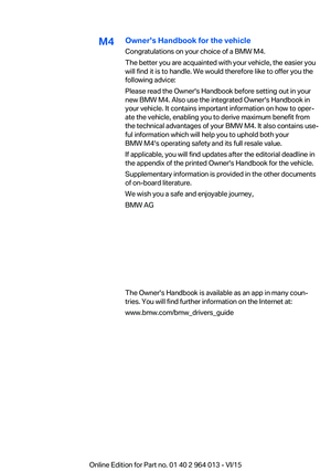 3
3 4
4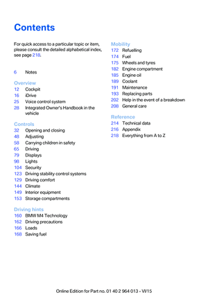 5
5 6
6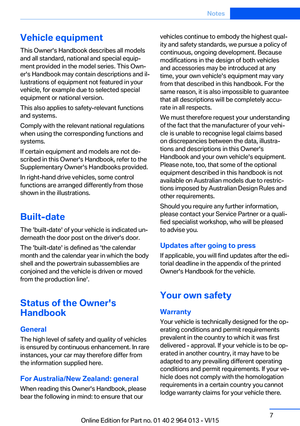 7
7 8
8 9
9 10
10 11
11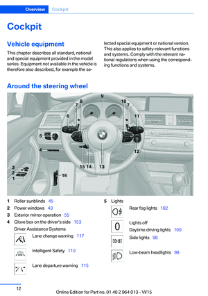 12
12 13
13 14
14 15
15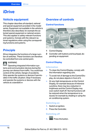 16
16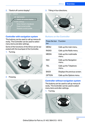 17
17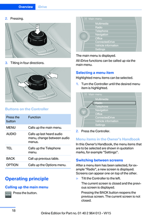 18
18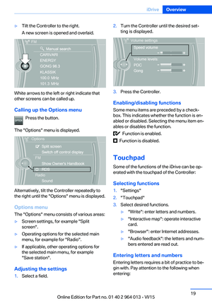 19
19 20
20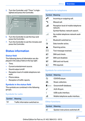 21
21 22
22 23
23 24
24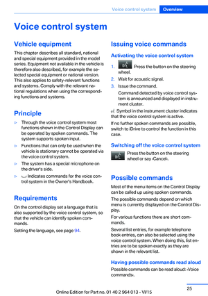 25
25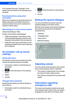 26
26 27
27 28
28 29
29 30
30 31
31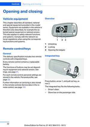 32
32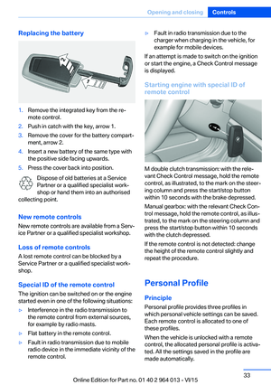 33
33 34
34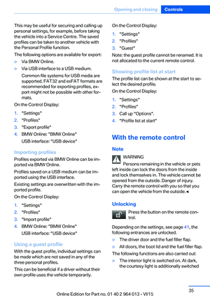 35
35 36
36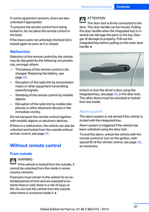 37
37 38
38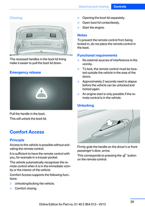 39
39 40
40 41
41 42
42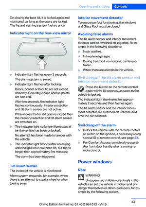 43
43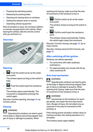 44
44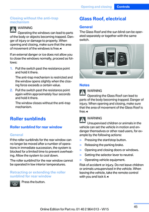 45
45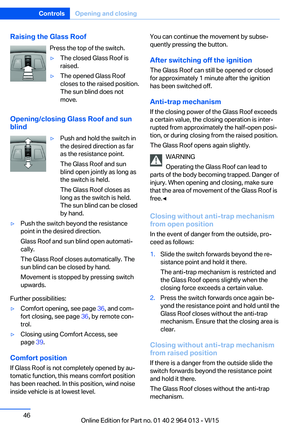 46
46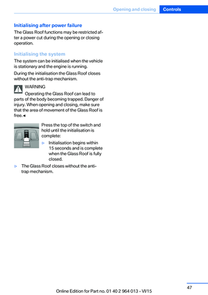 47
47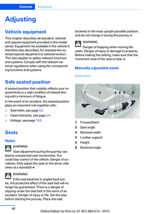 48
48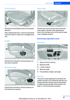 49
49 50
50 51
51 52
52 53
53 54
54 55
55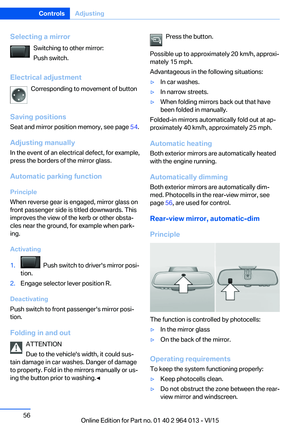 56
56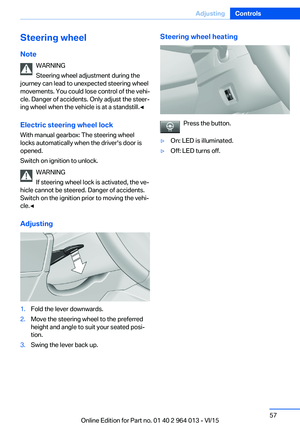 57
57 58
58 59
59 60
60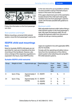 61
61 62
62 63
63 64
64 65
65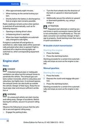 66
66 67
67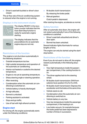 68
68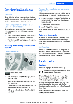 69
69 70
70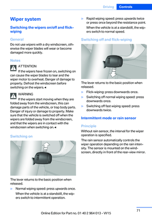 71
71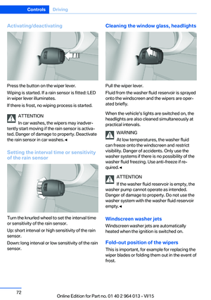 72
72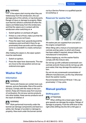 73
73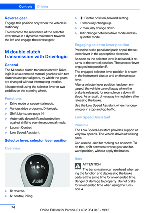 74
74 75
75 76
76 77
77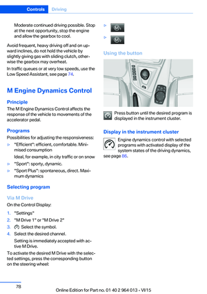 78
78 79
79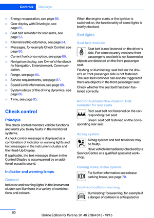 80
80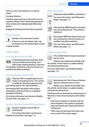 81
81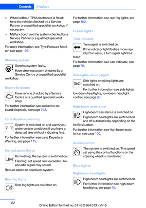 82
82 83
83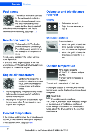 84
84 85
85 86
86 87
87 88
88 89
89 90
90 91
91 92
92 93
93 94
94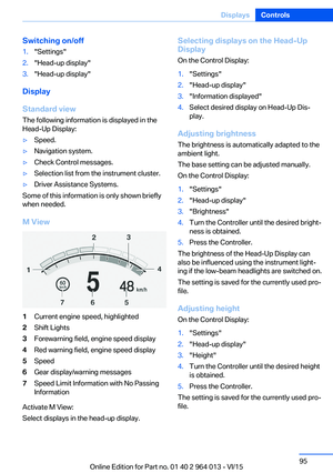 95
95 96
96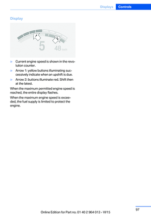 97
97 98
98 99
99 100
100 101
101 102
102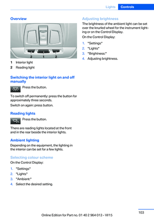 103
103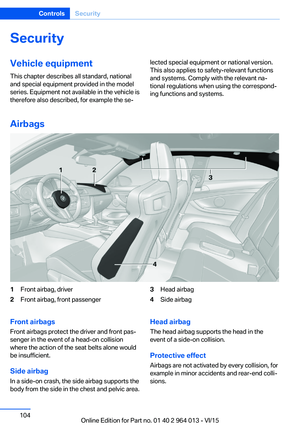 104
104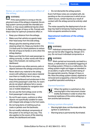 105
105 106
106 107
107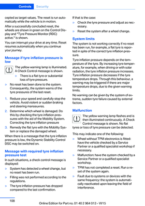 108
108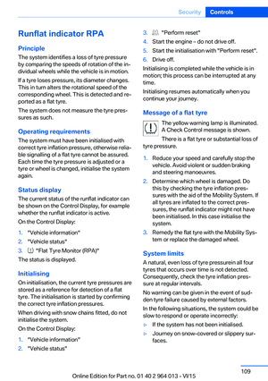 109
109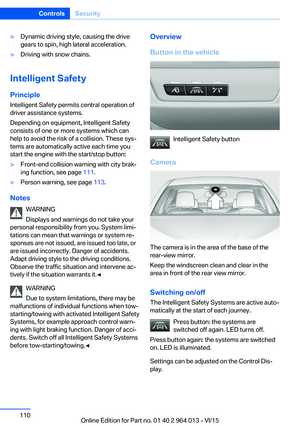 110
110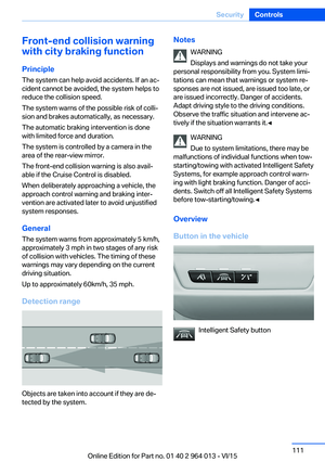 111
111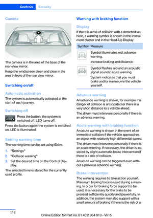 112
112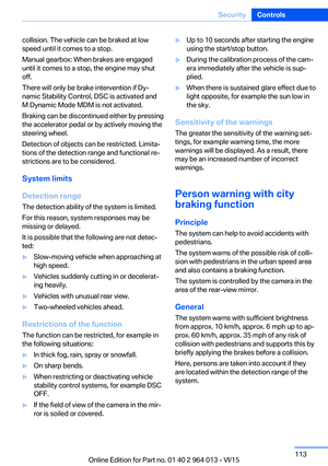 113
113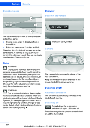 114
114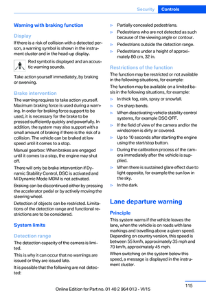 115
115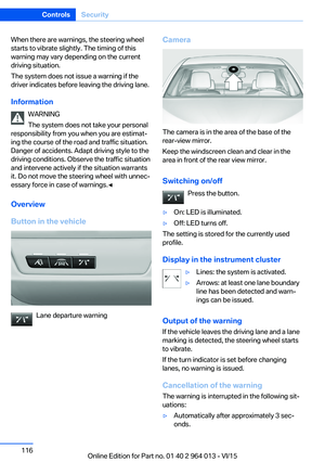 116
116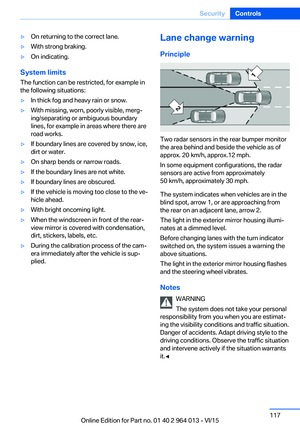 117
117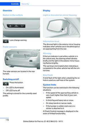 118
118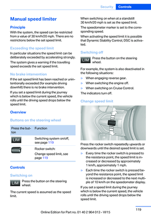 119
119 120
120 121
121 122
122 123
123 124
124 125
125 126
126 127
127 128
128 129
129 130
130 131
131 132
132 133
133 134
134 135
135 136
136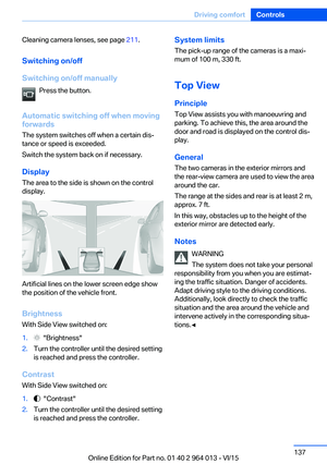 137
137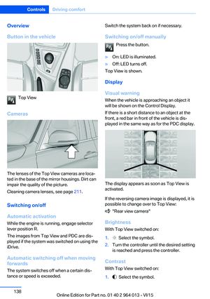 138
138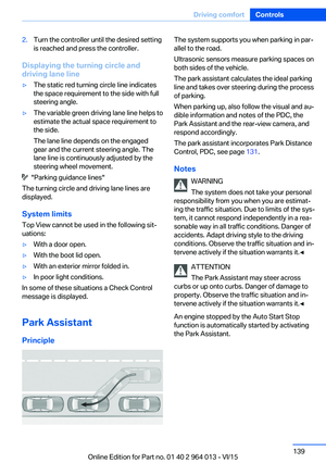 139
139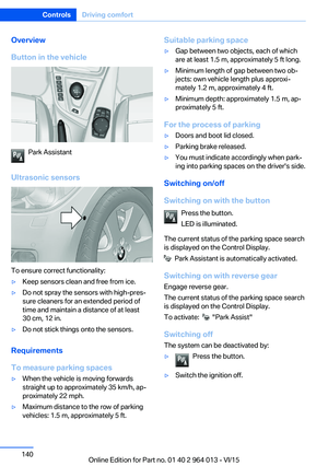 140
140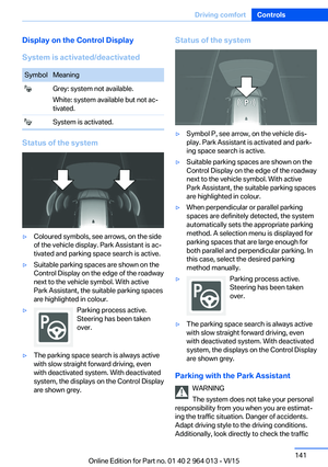 141
141 142
142 143
143 144
144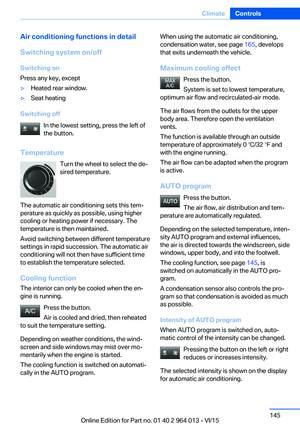 145
145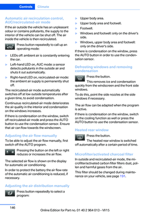 146
146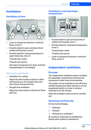 147
147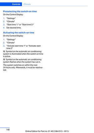 148
148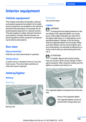 149
149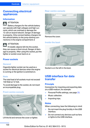 150
150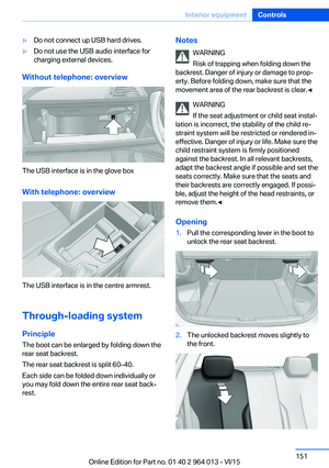 151
151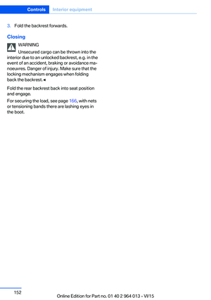 152
152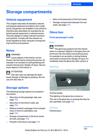 153
153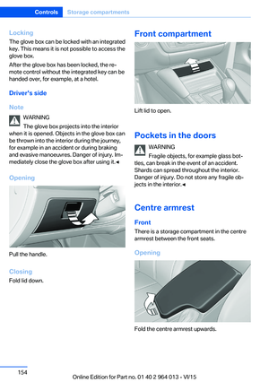 154
154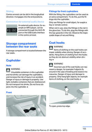 155
155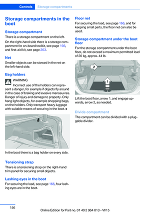 156
156 157
157 158
158 159
159 160
160 161
161 162
162 163
163 164
164 165
165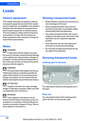 166
166 167
167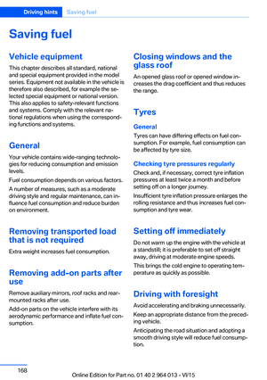 168
168 169
169 170
170 171
171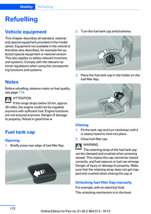 172
172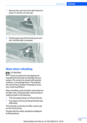 173
173 174
174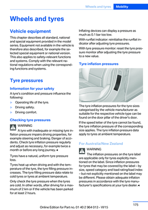 175
175 176
176 177
177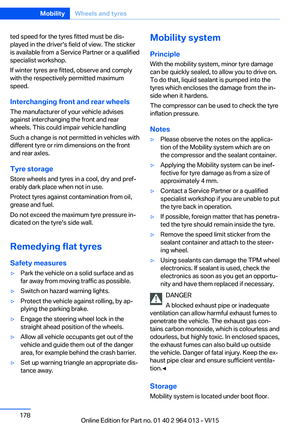 178
178 179
179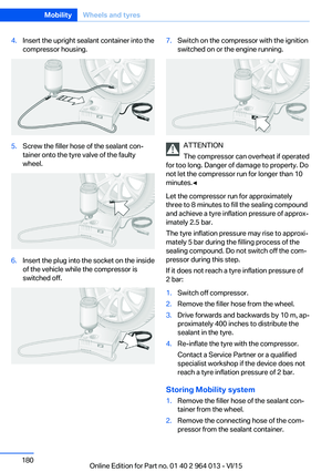 180
180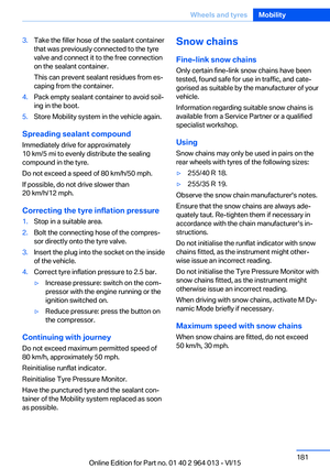 181
181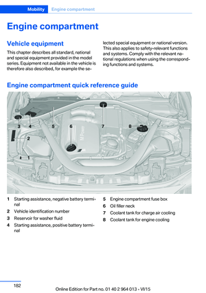 182
182 183
183 184
184 185
185 186
186 187
187 188
188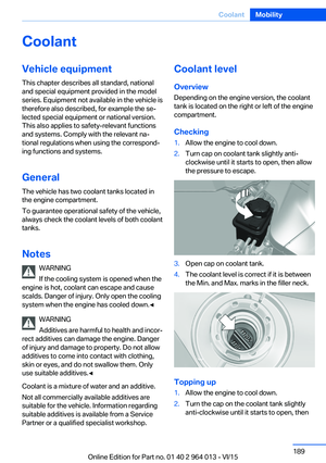 189
189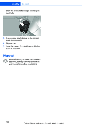 190
190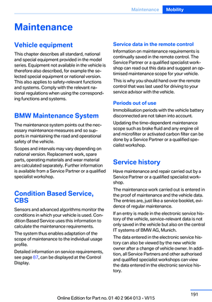 191
191 192
192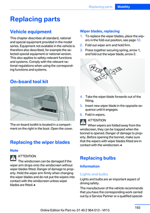 193
193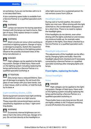 194
194 195
195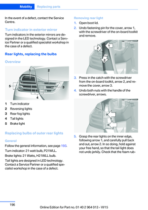 196
196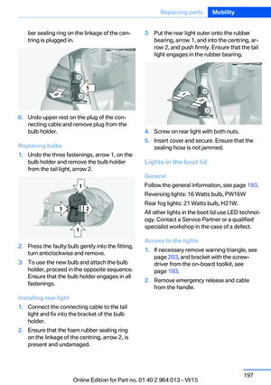 197
197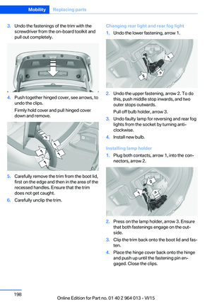 198
198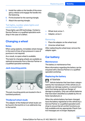 199
199 200
200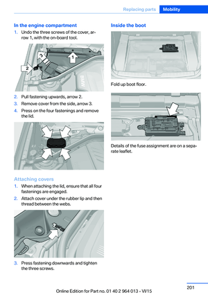 201
201 202
202 203
203 204
204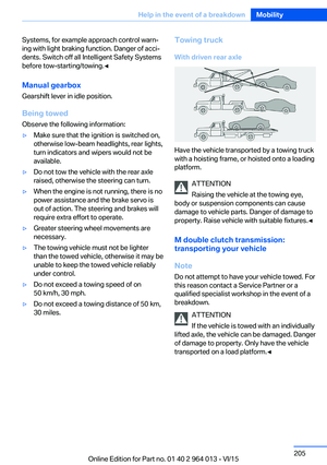 205
205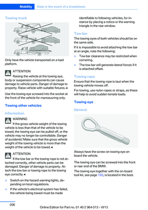 206
206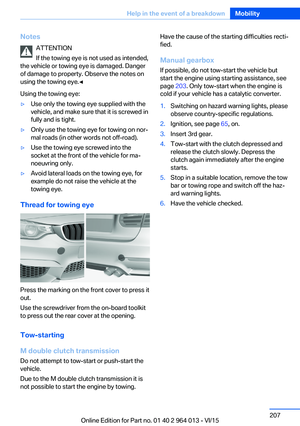 207
207 208
208 209
209 210
210 211
211 212
212 213
213 214
214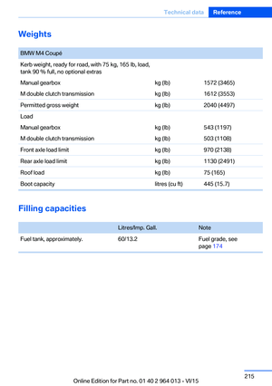 215
215 216
216 217
217 218
218 219
219 220
220 221
221 222
222 223
223 224
224 225
225 226
226 227
227