Page 65 of 81

122 || 123
HANDLING THE UNEXPECTED
HANDLING THE UNEXPECTED
TABLE OF
CONTENTS
INDEX
VISUAL INDEX
VOICE COMMAND INDEX
SAFETY
INFORMATION
CLIENT
INFORMATION
INSTRUMENT PANEL
SPECIFICATIONS
VEHICLE
CONTROLS
MAINTENANCE
AUDIO AND
CONNECTIVITY
HANDLING THE UNEXPECTED
BLUETOOTH®
HANDSFREELINK®
DRIVING
ACURALINK®
NAVIGATION
Replacing the Flat Tire
1. Remove the wheel nuts and flat tire.
2. Mount the compact spare tire. Replace the wheel
nuts, and lightly tighten them.
3. Lower the vehicle and remove the jack. Tighten
the wheel nuts in the order indicated in the
image. Go around, tightening the nuts, two to
three times in this order. Do not overtighten the
wheel nuts.
If you drive with the spare tire installed, the low tire pressure/TPMS indicator
appears. The indicator stays on until a regular tire is installed.
Storing the Flat Tire
1. Remove the center cap and place the flat tire
face up in the spare tire well.
2. Remove the spacer cone from the wing bolt for
the spare tire, and insert the wing bolt for the
regular tire back on the bolt. Secure the flat tire
with the wing bolt.
3. Securely store the jack and wheel nut wrench back in the tool case. Store the
case in the cargo area.
Loose items can fly around the interior in a crash and can seriously injure the
occupants.
Store the wheel, jack, and tools securely before driving.
WARNING
Wing
bolt
Spacer
cone For normal tire
For compact spare tire
Fuse Locations
If any electrical devices are not working, turn the vehicle off and check to see if any
applicable fuse is blown. Fuse locations are shown on the fuse box cover. Locate the
fuse by the fuse number and box cover number.
Engine Compartment Fuse Box Located near the brake fluid reservoir. Push the tabs to open the box.
Circuit ProtectedAmps
1
EPS70APower Tailgate Motor(40 A)ABS/VSA FS R20AABS/VSA Moto r40AE-DPS(30A )Main Fuse120A
2
�50 A
Fuse Box Main 160AFuse Box Main 260A
IG Main 50A
Headlight Washer(30 A)
Sub Fan Motor30A
Rear Defogger 40A
Main Fan Moto
r30A
Headlight Main 30A
Blowe
r40A
3
ST CUT140 AIG MAIN130ASUB FUSE MAIN(40 A)IG MAIN230A
4R ear Seat Heaters (20A )
5 STR Diagnosis Fus e7.5A
6A UDIO (ODMD) (15A)
7 � �
8� �
9� �
10 ��
11 Oil Level 7.5A
12 Fog Lights
*(20A )
13 Power Tailgate Closer (20A )
14 Hazard 10A
15 IGP2 15A
16 IG Coil 15A
17 Stop 10A
18 Horn1 0A
19 ACM 20A
20 Right Headlight Low Bea m15A
21 MG Clutch 7.5A
22 DBW1 5A
23 Left Headlight Low Beam 15A
24 DRL (10A )
25 FI Main 15A
26 Trailer (20A )
27 Small 20A
28 Interior Lights 7.5A
29 Back Up 10A
Circuit Protecte
dAmps
*
*
*
Circuit Protected Amps
1 EPS
70A
Power Tailgate Motor (40A)
ABS/VSA FS R 20A
ABS/VSA Moto r40A
E-DPS (30A)
Main Fuse 120A
2 �
50A
Fuse Box Main 160A
Fuse Box Main 260A
IG Main 50A
Headlight Washer (30A)
Sub Fan Moto r30A
Rear Defogger 40A
Main Fan Moto r30A
Headlight Main 30A
Blowe r4 0A
3 ST CUT1
40A
IG MAIN1 30A
SUB FUSE MAIN (40A)
IG MAIN2 30A
4R ear Seat Heaters (20A )5STR Diagnosis Fus e7.5A
6A UDIO (ODMD) (15A)
7��
8� �
9��
10��11Oil Level7.5A
12 Fog Lights*(20A )13Power Tailgate Closer(20A )
14 Hazard 10A
15IGP215A
16 IG Coil 15A
17Stop10 A
18 Horn10A19ACM20A
20 Right Headlight Low Bea m15A
21MG Clutch7.5A
22 DBW15A23Left Headlight Low Beam15A
24 DRL (10A )
25FI Main15A
26 Trailer (20A )
27Small20A
28 Interior Lights 7.5A
29Back Up10A
Circuit Protecte dAmps
*
*
*
*if equipped
Tab
Page 66 of 81

124 || 125
HANDLING THE UNEXPECTED
HANDLING THE UNEXPECTED
TABLE OF
CONTENTS
INDEX
VISUAL INDEX
VOICE COMMAND INDEX
SAFETY
INFORMATION
CLIENT
INFORMATION
INSTRUMENT PANEL
SPECIFICATIONS
VEHICLE
CONTROLS
MAINTENANCE
AUDIO AND
CONNECTIVITY
HANDLING THE UNEXPECTED
BLUETOOTH®
HANDSFREELINK®
DRIVING
ACURALINK®
NAVIGATION
Interior Fuse Box
Located under the dashboard. Inspecting and Changing Fuses
1. Turn the vehicle off, including the headlights and
accessories.
2. Remove the fuse box cover.
3. Check the large fuse in the engine compartment.
If the fuse is blown, use a Phillips-head
screwdriver to remove the screws and replace
the fuse with a new one. Reinstall the screws.
4. Inspect the small fuses in the engine
compartment and the vehicle interior.
If there is a burned out fuse, remove it with the
fuse puller and replace it with a new one.
Blown fuse
Combined
fuse
Fuse puller
Replacing a fuse with one that has a higher rating greatly increases the chances
of damaging the electrical system.
NOTICE
Circuit ProtectedAmps1��2ACG15 A3ODS7.5A4Fuel Pump15A5Meter7.5A6Rear Wiper10 A7VB SOL10A
8Front Right Side
Door Lock Motor (Unlock)15 A
9Rear Left Side
Door Lock Motor (Unlock )15A
10 Power Lumbar 7.5A
11Moonroof20A
12 Accessory Power Socket
(Center Console )20
A
13Washer Main15A
14 Seat Heaters 20A
15Driver’s Door Lock Motor
(Unlock)10A
16 Driver’s Power Seat Sliding2 0A
17Driver’s Power Seat Reclinin g20A
18Passenger’s Power Seat Slidin g20A
19ACC7.5A
20 ACC Key Lock 7.5A
21Daytime Running Lights7.5A
22 A/C 7.5A
23 Option 10A
24 ABS/VSA7 .5A
25 IDAS (10A )
26 Audio Amp 20
A
*1
30 A*2
27 Accessory Power Socket
(Front) 20
A
28 ��
29 SRS 10A
Circuit Protected
Amps
*1: Models without navigation system
*2: Models with navigation system
30
Driver’s Door Lock Motor
(Lock) 10
A
31 Smart 10A
32 Front Right Side
Door Lock Motor (Lock) 15
A
33 Rear Left Sid
e
Door Lock Motor (Lock) 15
A
34 Small Lights 7.5A
35 Illumination 7.5A
36 Rear Wiper Main 10A
37 Passenger’s Power Seat
Reclining 20
A
38 Left Headlight High Beam 10A
39 Right Headlight High Beam 10A
40 ��
41 Door Lock 20A
42 Driver’s Power Window 20A
43 Rear Right Side Power
Window 20
A
44 Front Right Side Power
Window 20
A
45 Rear Left Side Power
Window 20
A
46 Wiper3 0A
Circuit Protected Amps
1 � �
2 ACG 15A
3 ODS 7.5A
4 Fuel Pump 15A
5 Meter 7.5A
6 Rear Wiper 10A
7 VB SOL 10A
8 Front Right Side
Door Lock Motor (Unlock) 15
A
9 Rear Left Side
Door Lock Motor (Unlock )15
A
10 Power Lumbar 7.5A
11 Moonroof 20A
12 Accessory Power Socket
(Center Console )20
A
13 Washer Main 15A
14 Seat Heaters 20A
15 Driver’s Door Lock Motor
(Unlock) 10
A
16 Driver’s Power Seat Sliding2 0A
17
Driver’s Power Seat Reclinin g20A
18Passenger’s Power Seat Slidin g20A
19 ACC 7.5A
20 ACC Key Lock 7.5A
21 Daytime Running Light s7.5A
22 A/C 7.5A
23Option10 A
24 ABS/VSA7.5A25IDAS(10A )
26 Audio Amp 20
A*1
30 A*2
27Accessory Power Socket
(Front)20 A
28
��29SRS10 A
Circuit ProtectedAmps
*1: Models without navigation system*2: Models with navigation system
30
Driver’s Door Lock Motor
(Lock) 10
A
31Smar t10A
32 Front Right Side
Door Lock Motor (Lock) 15
A
33Rear Left Sid e
Door Lock Motor (Lock)15 A
34 Small Lights 7.5A
35Illumination7.5A
36 Rear Wiper Main 10A
37Passenger’s Power Seat
Reclining20 A
38 Left Headlight High Beam 10A
39Right Headlight High Beam10A
40��41Door Lock20 A
42 Driver’s Power Window 20A
43Rear Right Side Power
Window20A
44 Front Right Side Power
Window 20
A
45Rear Left Side Power
Window20A
46 Wipe
r30A
Fuse box
Fuse label
Page 67 of 81

126 || 127
MAINTENANCE
MAINTENANCE
TABLE OF
CONTENTS
INDEX
VISUAL INDEX
VOICE COMMAND INDEX
SAFETY
INFORMATION
CLIENT
INFORMATION
INSTRUMENT PANEL
SPECIFICATIONS
VEHICLE
CONTROLS
MAINTENANCE
AUDIO AND
CONNECTIVITY
HANDLING THE UNEXPECTED
BLUETOOTH®
HANDSFREELINK®
DRIVING
ACURALINK®
NAVIGATION
Learn about basic maintenance that you can perform on the vehicle yourself, as
well as information about how to best maintain the vehicle.
Safety Precautions
Some of the most important safety precautions are listed below; however,
we cannot warn you of every conceivable hazard that can arise in performing
maintenance. Only you can decide whether or not you should perform a given task.
Maintenance Safety
• To reduce the possibility of fire or explosion, keep cigarettes, sparks, and flames
away from the battery and all fuel-related parts.
• Never leave rags, towels, or other flammable objects under the hood.
• To clean parts, use a commercially available degreaser or parts cleaner, not
gasoline.
• Wear eye protection and protective clothing when working with the battery or
compressed air.
• Do not run the engine in confined spaces where carbon monoxide gas can
accumulate.
Vehicle Safety
• The vehicle must be stationary, and parked on level ground with the parking
brake set and the engine off.
• Be aware that hot parts can burn you.
• Be aware that moving parts can injure you.
MAINTENANCE
Improperly maintaining this vehicle or failing to correct a problem before
driving can cause a crash in which you can be seriously hurt or killed.
Always follow the inspection and maintenance recommendations according
to the schedules in this guide.
WARNING
Failure to properly follow maintenance instructions and precautions can
cause you to be seriously hurt or killed.
Always follow the procedures and precautions in this guide.
WARNING
Maintenance Minder™
When maintenance is due, the system message indicator comes on and the
Maintenance Minder appears on the multi-information display every time you
turn the vehicle on. Press the Info (p/q) buttons on the steering wheel to change
displays.
See page 128 to check the indicated maintenance service(s).
• Independent of the Maintenance Minder information, replace the brake fluid
every 3 years.
• Inspect idle speed every 160,000 miles (256,000 km).
• Adjust the valves during services A, B, 1, 2, or 3 if they are noisy.
U.S. models
Maintenance, replacement, or repair of emissions control devices and systems
may be done by any automotive repair establishment or individuals using parts
that are certified to EPA standards.
According to state and federal regulations, failure to perform maintenance on the
maintenance main items marked with # will not void your emissions warranties.
However, all maintenance services should be performed in accordance with the
intervals indicated by the multi-information display.
System
message
indicator Main
item
Sub item
Maintenance Minder
Main item Sub item
Models with full
color display
Models without
full color display
Page 68 of 81

128 || 129
MAINTENANCE
MAINTENANCE
TABLE OF
CONTENTS
INDEX
VISUAL INDEX
VOICE COMMAND INDEX
SAFETY
INFORMATION
CLIENT
INFORMATION
INSTRUMENT PANEL
SPECIFICATIONS
VEHICLE
CONTROLS
MAINTENANCE
AUDIO AND
CONNECTIVITY
HANDLING THE UNEXPECTED
BLUETOOTH®
HANDSFREELINK®
DRIVING
ACURALINK®
NAVIGATION
Maintenance Minder Service Codes
These codes indicate what services are due on your vehicle.
*1:If the message SERVICE DUE NOW does not appear more than 12 months after the display
is reset, change the engine oil every year.
#:See information on maintenance and emissions warranty.
*2:If you drive in dusty conditions, replace the air cleaner element every \
15,000 miles (24,000 km).
COD EMaintenance Main Items
A
�Replace engine oil*1
B�Replace engine oil*1 and oil �lter
�Inspect front and rear brakes
�Check parking brake ad justment
�Check expiration date for temporary tire repair kit bottle
�Inspect tie rod ends, steering gearbox, and boots
�Inspect suspension component s
�Inspect driveshaft boots
�Inspect brake hoses and lines (including ABS/VSA)
�Inspect all �uid levels and condition of �uids
�Inspect exhaust system#
�Inspect fuel lines and connections#
*3:If you drive primarily in urban areas that have high concentrations of s\
oot in the air from industryand diesel-powered vehicles, replace the dust and pollen �lter every \
15,000 miles (24,000 km).*4:Driving in mountainous areas at very low vehicle speeds or trailer towin\
g results in higher
transmission and transfer temperatures. This requires transmission and t\
ransfer �uid changes more
frequently than recommended by the Maintenance Minder. If you regularly drive your vehicle under
these conditions, have the transmission �uid changed at 60,000 miles \
(100,000 km), then ever y
30,000 miles (48,000 km).
*5: If you drive regularly in very high temperatures (over 110 °F/43 °C), in very low temperatures
(under -20 °F/-29 °C), or tow a trailer, replace every 60,000 mi\
les (100,000 km).
CODEMaintenance Sub Item s
1
�Rotate tire s
2�Replace air cleaner elemen t*2
�Replace dust and pollen �lte r*3
�Inspect drive belt
3
�Replace transmission �uid*4
4�Replace spark plugs
�Replace timing belt and inspect water pump*5
�Inspect valve clearance
5
�Replace engine coolant
6�Replace rear differential �uid*
(if equipped )
Under the Hood
Opening the Hood
1. Park the vehicle on a level surface, and set the
parking brake.
2. Pull the hood release handle under the lower left
corner of the dashboard.
3. Slide the hood latch lever in the center of the
hood to release the lock mechanism, and open
the hood.
4. Lift the hood up most of the way. The hydraulic
supports will lift it up the rest of the way and
hold it up.
When closing, lower it to approximately 12
inches (30 cm), then press down firmly with your
hands.
Hood release handle
Pull
Lever
Support rod Grip
Clamp
Engine oil fill cap Brake
fluid
(black cap)
Automatic
transmission
fluid dipstick
(yellow loop)
Washer
fluid
(blue cap) Battery
Engine coolant
reserve tank
Radiator cap
Engine oil dipstick
(orange loop)
Do not open the hood when the wiper arms are raised. The hood will strike the
wipers, and may damage the hood or the wipers.
NOTICE
Page 69 of 81

130 || 131
MAINTENANCE
MAINTENANCE
TABLE OF
CONTENTS
INDEX
VISUAL INDEX
VOICE COMMAND INDEX
SAFETY
INFORMATION
CLIENT
INFORMATION
INSTRUMENT PANEL
SPECIFICATIONS
VEHICLE
CONTROLS
MAINTENANCE
AUDIO AND
CONNECTIVITY
HANDLING THE UNEXPECTED
BLUETOOTH®
HANDSFREELINK®
DRIVING
ACURALINK®
NAVIGATION
Engine Oil
Park the vehicle on level ground, and wait approximately three minutes after
turning the engine off before you check the oil.
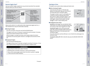
Checking the Oil
1. Remove the dipstick (orange loop).
2. Wipe the dipstick with a clean cloth or paper
towel.
3. Insert the dipstick all the way back into its hole.
4. Remove the dipstick again, and check the level. It
should be between the upper and lower marks.
Add oil if necessary.
Recommended Engine Oil
• Genuine Acura Motor Oil
• Premium-grade 0W-20 detergent oil with an API Certification Seal on the
container
This seal indicates the oil is energy conserving and
that it meets the American Petroleum Institute’s
latest requirements.
Use Genuine Acura Motor Oil or another
commercial engine oil of suitable viscosity for the
ambient temperature as shown.
You may also use synthetic motor oil if it is labeled with the API Certification Seal
and is of the specified viscosity grade.
Upper mark
Lower mark
Ambient temperature
Adding Oil
1. Unscrew and remove the engine oil fill cap.
2. Add oil slowly.
3. Reinstall the engine oil fill cap, and tighten it
securely.
4. Wait for three minutes and recheck the engine
oil dipstick.
Engine oil
fill cap
Resetting the Engine Oil Life
If you change or replace the vehicle’s engine oil yourself, you must reset the
engine oil life. Use the Info (p/q) and SEL/RESET buttons on the steering wheel
to make selections in the multi-information display.
1. Scroll to Vehicle Settings, and select it.
2. Scroll to Maintenance Info, and select it. The oil life
reset mode is displayed.
3. Select Reset. The maintenance items disappear, and
the engine oil life display returns to 100%.
Failure to reset the engine oil life after a maintenance service results in the
system showing incorrect maintenance intervals, which can lead to serious
mechanical problems.
NOTICE
Do not fill the engine oil above the upper mark. Overfilling the engine oil can
result in leaks and engine damage.
NOTICE
Page 70 of 81

132 || 133
MAINTENANCE
MAINTENANCE
TABLE OF
CONTENTS
INDEX
VISUAL INDEX
VOICE COMMAND INDEX
SAFETY
INFORMATION
CLIENT
INFORMATION
INSTRUMENT PANEL
SPECIFICATIONS
VEHICLE
CONTROLS
MAINTENANCE
AUDIO AND
CONNECTIVITY
HANDLING THE UNEXPECTED
BLUETOOTH®
HANDSFREELINK®
DRIVING
ACURALINK®
NAVIGATION
Engine Coolant
Park the vehicle on level ground. Check the reserve tank and the coolant level in the
radiator. We recommend Acura Long Life Antifreeze/Coolant Type 2.
Checking the Reserve Tank
1. Check the amount of coolant in the reserve tank.
2. If the coolant level is below the MIN mark, add
the specified coolant until it reaches the MAX
mark.
3. Inspect the cooling system for leaks.
Adding Coolant
1. Make sure the engine and radiator are cool.
2. Turn the radiator cap counterclockwise and
relieve any pressure in the coolant system. Do
not push the cap down when turning.
3. Push down and turn the radiator cap
counterclockwise to remove it.
4. The coolant level should be up to the base of the
filler neck. Add coolant if it is low.
5. Put the radiator cap back on, and tighten it fully.
6. Pour coolant into the reserve tank until it
reaches the MAX mark. Put the cap back on the
reserve tank.
Removing the radiator cap while the engine is hot can cause the coolant to
spray out, seriously scalding you.
Always let the engine and radiator cool down before removing the radiator
cap.
WARNING
Reserve tank MAX
MIN
Radiator cap
If temperatures consistently below −22°F (−30°C) are expected, the coolant
mixture should be changed to a higher concentration. Consult your dealer for
more information.
NOTICE
Pour the fluid slowly and carefully so you do not spill any. Clean up any spills
immediately; they can damage components in the engine compartment.
NOTICE
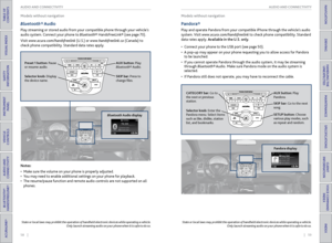
Window Washer Fluid
Check the amount of window washer fluid using the
1/2 mark on the reservoir. If the level is low, fill the
washer reservoir. Pour the washer fluid carefully. Do
not overflow the reservoir.
Canadian models
If the washer fluid is low, a message appears on the
multi-information display.
1/2 mark
Do not use engine antifreeze or a vinegar/water solution in the windshield
washer reservoir. Antifreeze can damage your vehicle’s paint. A vinegar/water
solution can damage the windshield washer pump.
NOTICE
Checking the Battery
Check the battery terminals for corrosion monthly.
For jump starting, see page 114.
The battery gives off explosive hydrogen gas during normal operation.
A spark or flame can cause the battery to explode with enough force to kill or
seriously hurt you.
When conducting any battery maintenance, wear protective clothing and a
face shield, or have a skilled technician do it.
WARNING
WARNING: Battery posts, terminals, and related accessories contain lead and lead
compounds. Wash your hands after handling.
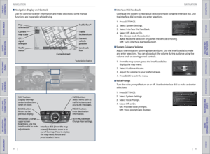
Brake Fluid
The fluid level should be between the MIN and MAX marks on the side of the
reservoir. We recommend using Acura Heavy Duty Brake Fluid DOT 3.
Pour the fluid carefully.
If the fluid level is at or below the MIN mark, have a
dealer inspect for leaks or worn brake pads as soon as
possible.
Brake fluid marked DOT 5 is not compatible with your vehicle’s braking system
and can cause extensive damage.
NOTICE
Brake reservoir MAX
MIN
Page 71 of 81

134 || 135
MAINTENANCE
MAINTENANCE
TABLE OF
CONTENTS
INDEX
VISUAL INDEX
VOICE COMMAND INDEX
SAFETY
INFORMATION
CLIENT
INFORMATION
INSTRUMENT PANEL
SPECIFICATIONS
VEHICLE
CONTROLS
MAINTENANCE
AUDIO AND
CONNECTIVITY
HANDLING THE UNEXPECTED
BLUETOOTH®
HANDSFREELINK®
DRIVING
ACURALINK®
NAVIGATION
Changing Wiper Blades
If the wiper blades leave streaks across the windshield, try cleaning them first
with a paper towel or soft cloth and wiper fluid. If the wiper blade rubber has
deteriorated, you should change the wiper blades.
Front Wiper Blades
1. Lift the driver side wiper arm first, then the
passenger side.
2. Place a cloth on the edge of the lock tab. Push
the lock tab up with a flat-tip screwdriver.
3. Slide the blade from the wiper arm.
4. Slide the wiper blade out from its holder by
pulling the tabbed end out.
5. Remove the retainers from the rubber blade that
has been removed, and mount to a new rubber
blade. Correctly align the rubber protrusion and
the retainer grooves.
6. Slide the new wiper blade onto the holder from
the bottom end. The tab on the holder should fit
in the indent of the wiper blade.
7. Slide the wiper blade onto the wiper arm, then
push down the lock tab.
8. Lower the passenger side wiper arm first, then
the driver side.
Lock tab
Blade
Top Retainer
Blade
Indent
Tab
Avoid dropping the wiper arm, as it may damage the windshield.
NOTICE
Rear Wiper Blade 1. Raise the wiper arm off.
2. Slide the wiper blade out from the end with the
indent.
3. Remove the retainers from wiper blade and
mount to a new rubber blade.
4. Slide the wiper blade onto the holder. Make sure
it is engaged correctly, then install the wiper
blade assembly onto the wiper arm.
Blade
Retainer
Rubber
Page 72 of 81

136 || 137
MAINTENANCE
MAINTENANCE
TABLE OF
CONTENTS
INDEX
VISUAL INDEX
VOICE COMMAND INDEX
SAFETY
INFORMATION
CLIENT
INFORMATION
INSTRUMENT PANEL
SPECIFICATIONS
VEHICLE
CONTROLS
MAINTENANCE
AUDIO AND
CONNECTIVITY
HANDLING THE UNEXPECTED
BLUETOOTH®
HANDSFREELINK®
DRIVING
ACURALINK®
NAVIGATION
Tire Information
To safely operate your vehicle, your tires must be of the proper type and size, in
good condition with adequate tread, and properly inflated.
Inflation Guidelines
• Properly inflated tires provide the best combination of handling, tread life, and
comfort. Refer to the driver’s doorjamb label or the specifications (see page
143) for the specified pressure.
• Underinflated tires wear unevenly, adversely affect handling and fuel economy,
and are more likely to fail from overheating.
• Overinflated tires make your vehicle ride harshly, are more prone to road
hazards, and wear unevenly.
• Every day before you drive, look at each of the tires. If one looks lower than the
others, check the pressure with a tire gauge.
• Measure the air pressure when tires are cold. This means the vehicle has been
parked for at least 3 hours, or driven less than 1 mile (1.6 km). If necessary, add
or release air until the specified pressure is reached. If checked when hot, tire
pressure can be as much as 4-6 psi (30-40 kPa, 0.3-0.5 kgf/cm
2) higher than
checked when cold.
• At least once a month or before long trips, use a gauge to measure the pressure
in all tires, including the spare. Even tires in good condition can lose 1-2 psi
(10-20 kPa, 0.1-0.2 kgf/cm
2) per month.
Inspection Guidelines
Every time you inflate the tires, check for the following:
• Any damage to tires, including bumps, bulges, cuts, splits, or cracks in the side
or tread. Remove any foreign objects and inspect for air leaks. Replace tires if
you see fabric or cord.
• Uneven or excessive tread wear. Have a dealer check the wheel alignment.
• Cracks or other damage around the valve stems.
Wear Indicators
The groove where the wear indicator is located is
1/16 inch (1.6 mm) shallower than elsewhere on the
tire. If the tread has worn so low that the indicator
is exposed, replace the tire. Worn out tires have
poor traction on wet roads.
Example of a wear
indicator mark
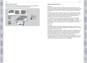
Tire and Loading Information Label
The label attached to the driver’s doorjamb provides necessary tire and
loading information. Using
tires that are excessively worn or improperly inflated can cause
a crash in which you can be seriously hurt or killed.
Follow all instructions in this owner’s manual regarding tire inflation
and maintenance.
WARNING
Original
tire sizes Number of
people your
vehicle can carry Proper
cold tire
pressureTotal weight
your vehicle
can carry (do
not exceed)
Tire and Wheel Replacement
Replace your tires with radials of the same size, load range, speed rating, and
maximum cold tire pressure rating (as shown on the tire’s sidewall). Using
tires of a different size or construction can cause certain vehicle systems to
work incorrectly. It is best to replace all four tires at the same time. If that isn’t
possible, replace the front or rear tires in pairs.
If you change or replace a wheel, make sure that the wheel’s specifications match
those of the original wheels. Only use TPMS-specified wheels approved for your
vehicle.
Installing improper tires on your vehicle can affect handling and stability.
This can cause a crash in which you can be seriously hurt or killed.
Always use the size and type of tires recommended in the owner’s manual.
WARNING