Page 57 of 124

INSTRUMENT AND CONTROL FUNCTIONS
3-42
3
EAU39672
Rear view mirrorsThe rear view mirrors of this vehicle
can be folded forward or backward for
parking in narrow spaces. Fold the mir-
rors back to their original position be-
fore riding.
WARNING
EWA14372
Be sure to fold the rear view mirrors
back to their original position before
riding.
EAU55424
Adjusting the front and rear
suspensionThis model is equipped with an elec-
tronically adjustable suspension sys-
tem. The preload of the rear shock
absorber and the damping forces of
both the front fork and rear shock ab-
sorber can be adjusted.
WARNING
EWA12423
Be sure to stop the vehicle before
making any setting changes to the
multi-function meter unit. Changing
settings while riding can distract the
operator and increase the risk of an
accident.Preload
When riding with luggage or a passen-
ger, use the preload adjusting function
to adjust the suspension system to
match the load. There are 4 preload
settings.TIPThe preload adjusting function will
appear only when the engine is
running.Changing the preload setting will
also adjust the front and rear sus-
pension damping forces accord-
ingly. See “Damping force” on
page 3-44 for more information.
About cold temperature opera-
tion:
• When using the preload adjust-
ing function, there should be no
weight on the vehicle.
• When using the preload adjust-
ing function at ambient temper-
atures near or below 0 °C (32
°F), to protect the preload ad-
justing function motor, the elec-
tronically adjustable suspension
system warning light may come
on.
• The suspension will still operate
as normal, only the preload ad-
justing function cannot be used.
• To reset the electronically ad-
justable suspension system
warning light, wait approximate-
ly 6 minutes and then turn the
key to “OFF” or immediately
turn the key to “OFF” and then
wait 6 minutes.
1. Riding position
2. Parking position
2 2
1
221
U1MDE1E0.book Page 42 Monday, July 28, 2014 10:48 AM
Page 58 of 124

INSTRUMENT AND CONTROL FUNCTIONS
3-43
3• If the electronically adjustable
suspension system warning
light remains on, have a
Yamaha dealer check the sus-
pension system.
To adjust the preload1. Turn the key to “ON”, start the en-
gine, and then shift the transmis-
sion into neutral.
2. Push the menu switch “MENU” to
switch the function display to the
preload adjusting function.3. Use the select switch to select the
desired preload setting pictogram.
Select the suitable setting from
the following 4 pictograms ac-
cording to your load condition.While the preload is being adjust-
ed, the information display will
show a group of dots moving in a
circle. Once the selected picto-
gram returns, the preload adjust-
ment is complete.1. Function display
2. Preload adjusting function
3. Preload setting pictogram
GEARN
132
1. Menu switch “MENU”
2. Select switch “ / ”
1
2
1. Solo riding
2. Solo riding and luggage
3. Passenger riding
4. Passenger riding and luggage1
2
3
4
GEARN
GEARN
U1MDE1E0.book Page 43 Monday, July 28, 2014 10:48 AM
Page 59 of 124

INSTRUMENT AND CONTROL FUNCTIONS
3-44
3 While the preload is being adjusted,
the information display may change as
follows.
If the key is turned to “OFF” or the
engine is stopped while the pre-
load is being set, the following
preload setting pictogram will
flash to alert you that the current
preload setting does not match
the pictogram. If this occurs, ad-
just the preload again.
If the vehicle starts moving, the
following preload setting picto-
gram will flash to alert you that the
current preload setting does not
match the pictogram. If this oc-
curs, stop the vehicle and adjust
the preload again.If the preload is adjusted repeat-
edly, the preload setting picto-
gram will flash 4 times and the
preload cannot be adjusted. Wait
approximately 6 minutes for the
preload adjusting function motor
to cool down, and then try adjust-
ing the preload again.Damping force
Within each preload setting there are 3
damping force settings: “HARD”
(hard), “STD” (standard) and “SOFT”
(soft). When the preload setting is
changed, the damping force settings
will change accordingly. (The electron-
ically adjustable suspension system
will automatically adjust to the damp-
ing force settings last set for that pre-
load setting.) To further finely adjust
the damping force, each damping
force setting can be set to 7 different
levels.
GEARN
GEARN
GEAR1HARD
+3
GEARNGEARN
GEARN
1. Damping force setting
2. Damping force setting level
GEARNHARD
+3
21
U1MDE1E0.book Page 44 Monday, July 28, 2014 10:48 AM
Page 60 of 124

INSTRUMENT AND CONTROL FUNCTIONS
3-45
3
TIPIf the preload setting was not complet-
ed correctly:
The damping force setting and
setting level will flash 4 times and
cannot be adjusted if you try to
adjust them while the vehicle is
stopped.
The preload setting pictogram will
flash and the damping force can-
not be adjusted if you try to adjust
it while the vehicle is moving.
Be sure that the preload has been set
correctly before adjusting the damping
force.To adjust the damping force anddamping force setting level1. Turn the key to “ON”.
2. Push the menu switch “MENU” to
switch the function display to the
damping force adjusting function.3. Use the select switch to select
“HARD”, “STD” or “SOFT”.
4. Push the menu switch “MENU”.
5. Use the select switch to select the
desired level for the damping
force setting.
TIPThe damping force setting can be set to
7 levels (+3, +2, +1, 0, …1, …2 and …3).
softest level.6.
If the vehicle moves while you are ad-
justing the damping force, the informa-
tion display will change to the display
mode.
1. Function display
2. Damping force adjusting function
1. Damping force setting
GEARN
STD
0
12
GEARNHARD
0
1
1. Damping force setting level
GEARNHARD
+3
1
U1MDE1E0.book Page 45 Monday, July 28, 2014 10:48 AM
Page 61 of 124

INSTRUMENT AND CONTROL FUNCTIONS
3-46
3
WARNING
EWA16421
The rear shock absorber assembly
contains highly pressurized nitrogen
gas. Read and understand the fol-
lowing information before handling
the shock absorber assembly.
Do not tamper with or attempt
to open the cylinder assembly.
Do not subject the shock ab-
sorber assembly to an open
flame or other high heat source.
This may cause the unit to ex-
plode due to excessive gas
pressure.Do not deform or damage the
cylinder in any way. Cylinder
damage will result in poor
damping performance.
Do not dispose of a damaged or
worn-out shock ab
sorber as-
sembly yourself. Take the shock
absorber assembly to a Yamaha
dealer for any service.
EAU55592
SidestandThe sidestand is located on the left
side of the frame. Raise the sidestand
or lower it with your foot while holding
the vehicle upright.TIPThe built-in sidestand switch is
part of the ignition circuit cut-off
system, which cuts the ignition in
certain situations. (See the follow-
ing section for an explanation of
the ignition circuit cut-off system.)
The sidestand switch is also part
of the YCC-S system. Shifting out
of neutral is impossible when the
sidestand is down.
WARNING
EWA10242
The vehicle must not be ridden with
the sidestand down, or if the side-
stand cannot be properly moved up
(or does not stay up), otherwise the
sidestand could contact the ground
and distract the operator, resulting
in a possible loss of control.
Yamaha’s ignition circuit cut-off
system has been designed to assist
1. Damping force adjusting function
2. Damping force setting
3. Preload setting pictogram
GEARNHARD
+3
GEAR1HARD
+3
123
U1MDE1E0.book Page 46 Monday, July 28, 2014 10:48 AM
Page 62 of 124
INSTRUMENT AND CONTROL FUNCTIONS
3-47
3the operator in fulfilling the respon-
sibility of raising the sidestand be-
fore starting off. Therefore, check
this system regularly and have a
Yamaha dealer repair it if it does not
function properly.
EAU55362
Ignition circuit cut-off systemThe ignition circuit cut-off system
(comprising the sidestand switch and
brake light switches) has the following
functions.
It prevents starting when the side-
stand is up, but neither brake is
applied.
It prevents starting when either
brake is applied, but the sidestand
is still down.
It cuts the running engine when
the sidestand is moved down.
Periodically check the operation of the
ignition circuit cut-off system accord-
ing to the following procedure.
U1MDE1E0.book Page 47 Monday, July 28, 2014 10:48 AM
Page 63 of 124

INSTRUMENT AND CONTROL FUNCTIONS
3-48
3
With the engine turned off:
1. Place the vehicle on the centerstand.
2. Move the sidestand down.
3. Make sure that the start/engine stop switch is set to “ ”.
4. Turn the key to “ON”.
5. Shift the transmission into the neutral position.
6. Keep the front or rear brake applied.
7. Push the “ ” side of the start/engine stop switch.
Does the engine start?
With the engine still running:
8. Move the sidestand up.
9. Shift the transmission into gear.
10. Move the sidestand down.
Does the engine stall?
After the engine has stalled:
11. Move the sidestand up.
12. Release the brake.
13. Push the “ ” side of the start/engine stop switch.
Does the engine start?
The system is OK. The motorcycle can be ridden.
NO
YES YES NO YES
NO
The neutral switch, a brake light switch or the
YCC-S system may not be working correctly.
The motorcycle should not be ridden until
checked by a Yamaha dealer.
A brake light switch may not be working correctly.
The motorcycle should not be ridden until
checked by a Yamaha dealer.The sidestand switch may not be working correctly.
The motorcycle should not be ridden until
checked by a Yamaha dealer.• The vehicle must be placed on the center-
stand during this inspection.• If a malfunction is noted, have a Yamaha
dealer check the system before riding.
WA R N I N G
TIPThe traction control system indicator/warning
light “TCS” may come on, but this is not a
malfunction.
U1MDE1E0.book Page 48 Monday, July 28, 2014 10:48 AM
Page 64 of 124

INSTRUMENT AND CONTROL FUNCTIONS
3-49
3
EAU39656
Auxiliary DC jack
WARNING
EWA14361
To prevent electrical shock or short-
circuiting, make sure that the cap is
installed when the auxiliary DC jack
is not being used.NOTICE
ECA15432
The accessory connected to the
auxiliary DC jack should not be used
with the engine turned off, and the
load must never exceed 30 W (2.5 A),
otherwise the fuse may blow or the
battery may discharge.This vehicle is equipped with an auxil-
iary DC jack in the accessory box.
A 12-V accessory connected to the
auxiliary jack can be used when the
key is in the “ON” position and should
only be used when the engine is run-
ning.
To use the auxiliary DC jack
1. Open the accessory box lid. (See
page 3-39.)
2. Turn the key to “OFF”.3. Remove the auxiliary DC jack cap.
4. Turn the accessory off.
5. Insert the accessory plug into the
auxiliary DC jack.
6. Turn the key to “ON”, and then
start the engine. (See page 5-1.)
7. Turn the accessory on.
1. Auxiliary DC jack cap
1. Auxiliary DC jack
11
U1MDE1E0.book Page 49 Monday, July 28, 2014 10:48 AM
 1
1 2
2 3
3 4
4 5
5 6
6 7
7 8
8 9
9 10
10 11
11 12
12 13
13 14
14 15
15 16
16 17
17 18
18 19
19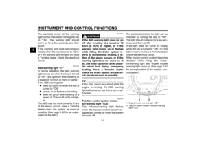 20
20 21
21 22
22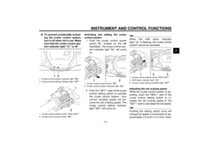 23
23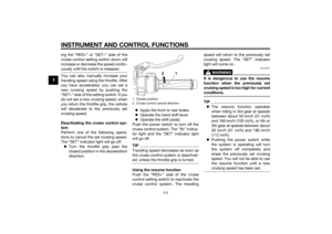 24
24 25
25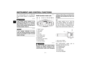 26
26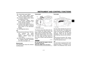 27
27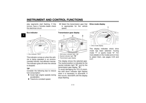 28
28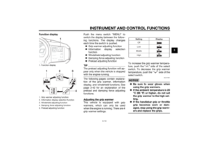 29
29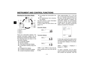 30
30 31
31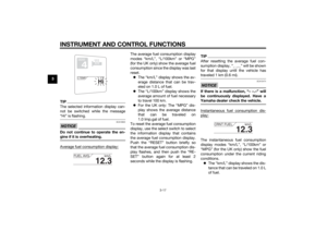 32
32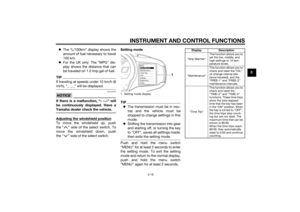 33
33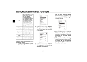 34
34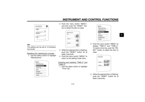 35
35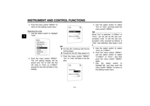 36
36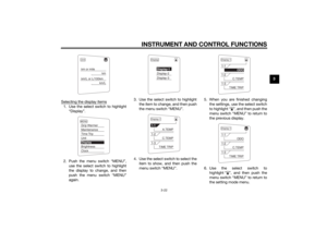 37
37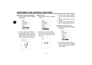 38
38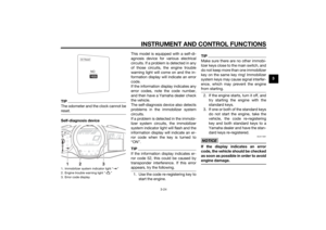 39
39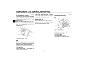 40
40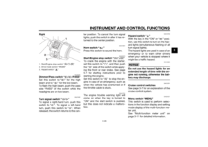 41
41 42
42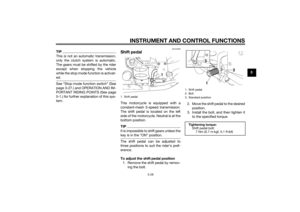 43
43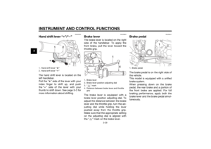 44
44 45
45 46
46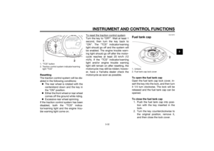 47
47 48
48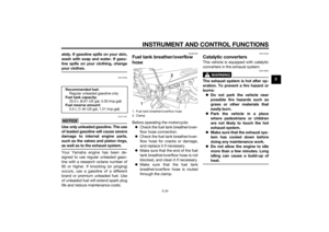 49
49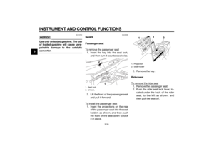 50
50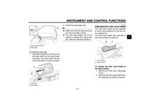 51
51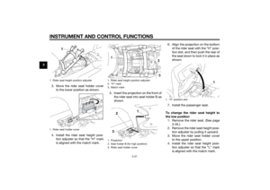 52
52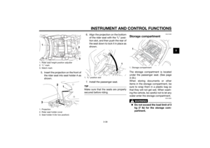 53
53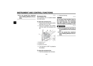 54
54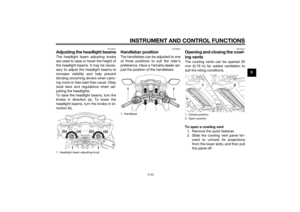 55
55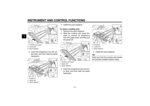 56
56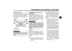 57
57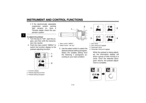 58
58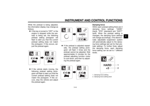 59
59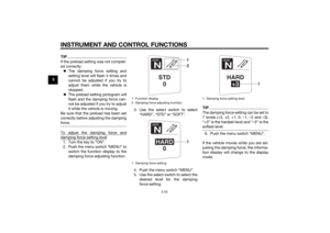 60
60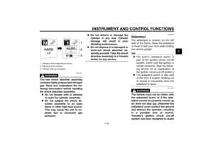 61
61 62
62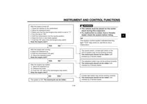 63
63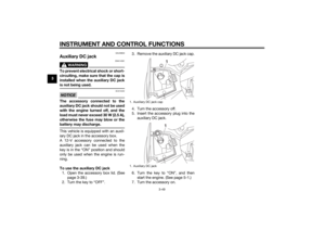 64
64 65
65 66
66 67
67 68
68 69
69 70
70 71
71 72
72 73
73 74
74 75
75 76
76 77
77 78
78 79
79 80
80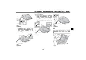 81
81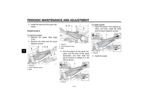 82
82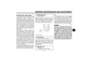 83
83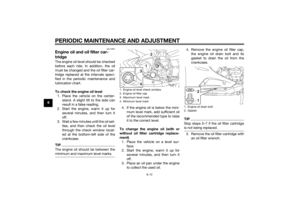 84
84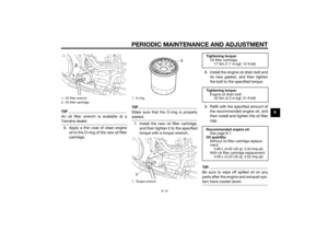 85
85 86
86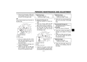 87
87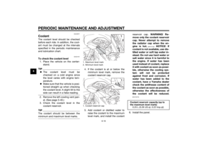 88
88 89
89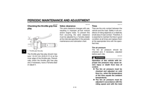 90
90 91
91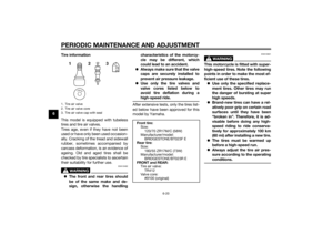 92
92 93
93 94
94 95
95 96
96 97
97 98
98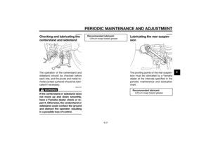 99
99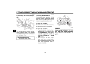 100
100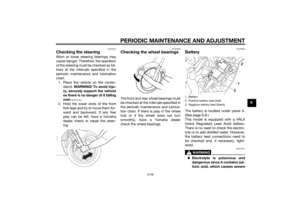 101
101 102
102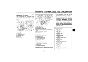 103
103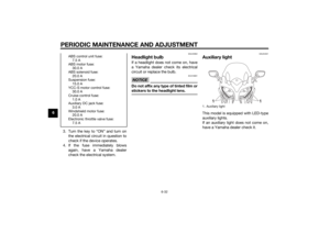 104
104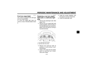 105
105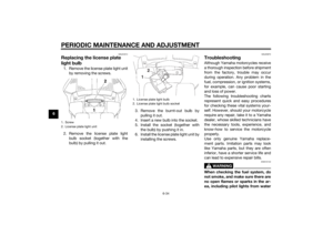 106
106 107
107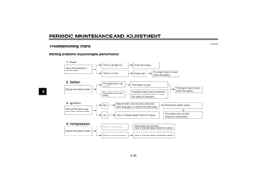 108
108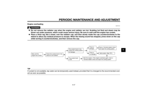 109
109 110
110 111
111 112
112 113
113 114
114 115
115 116
116 117
117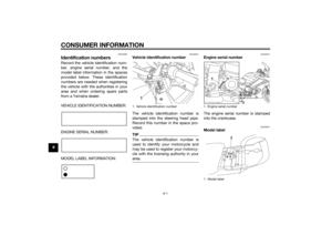 118
118 119
119 120
120 121
121 122
122 123
123