Page 49 of 124

INSTRUMENT AND CONTROL FUNCTIONS
3-34
3 ately. If gasoline spills on your skin,
wash with soap and water. If gaso-
line spills on your clothing, change
your clothes.
EAU13323
NOTICE
ECA11401
Use only unleaded gasoline. The use
of leaded gasoline will cause severe
damage to internal engine parts,
such as the valves and piston rings,
as well as to the exhaust system.Your Yamaha engine has been de-
signed to use regular unleaded gaso-
line with a research octane number of
95 or higher. If knocking (or pinging)
occurs, use a gasoline of a different
brand or premium unleaded fuel. Use
of unleaded fuel will extend spark plug
life and reduce maintenance costs.
EAUB1302
Fuel tank breather/overflow
hoseBefore operating the motorcycle:
Check the fuel tank breather/over-
flow hose connection.
Check the fuel tank breather/over-
flow hose for cracks or damage,
and replace it if necessary.
Make sure that the end of the fuel
tank breather/overflow hose is not
blocked, and clean it if necessary.
Make sure that the fuel tank
breather/overflow hose is routed
through the clamp.
EAU13446
Catalytic convertersThis vehicle is equipped with catalytic
converters in the exhaust system.
WARNING
EWA10863
The exhaust system is hot after op-
eration. To prevent a fire hazard or
burns:
Do not park the vehicle near
possible fire hazards such as
grass or other materials that
easily burn.
Park the vehicle in a place
where pedestrians or children
are not likely to touch the hot
exhaust system.
Make sure that the exhaust sys-
tem has cooled down before
doing any maintenance work.
Do not allow the engine to idle
more than a few minutes. Long
idling can cause a build-up of
heat.
Recommended fuel:
Regular unleaded gasoline only
Fuel tank capacity:
25.0 L (6.61 US gal, 5.50 Imp.gal)
Fuel reserve amount:
5.5 L (1.45 US gal, 1.21 Imp.gal)
1. Fuel tank breather/overflow hose
2. Clamp
2
1
U1MDE1E0.book Page 34 Monday, July 28, 2014 10:48 AM
Page 50 of 124
INSTRUMENT AND CONTROL FUNCTIONS
3-35
3
NOTICE
ECA10702
Use only unleaded gasoline. The use
of leaded gasoline will cause unre-
pairable damage to the catalytic
converter.
EAU39496
SeatsPassenger seat
To remove the passenger seat1. Insert the key into the seat lock,
and then turn it counterclockwise.
2. Lift the front of the passenger seat
and pull it forward.
To install the passenger seat1. Insert the projections on the rear
of the passenger seat into the seat
holders as shown, and then push
the front of the seat down to lock
it in place.2. Remove the key.
Rider seat
To remove the rider seat
1. Remove the passenger seat.
2. Push the rider seat lock lever, lo-
cated under the back of the rider
seat, to the left as shown, and
then pull the seat off.
1. Seat lock
2. Unlock.
1 2
1. Projection
2. Seat holder
U1MDE1E0.book Page 35 Monday, July 28, 2014 10:48 AM
Page 51 of 124
INSTRUMENT AND CONTROL FUNCTIONS
3-36
3
To install the rider seat
1. Insert the projection on the front of
the rider seat into the seat holder
as shown, and then push the rear
of the seat down to lock it in place.2. Install the passenger seat.
TIPMake sure that the seats are prop-
erly secured before riding.
The rider seat height can be ad-
justed to change the riding posi-
tion. (See the following section.)
EAU39633
Adjusting the rider seat heightThe rider seat height can be adjusted
to one of two positions to suit the rid-
er’s preference.
The rider seat height was adjusted to
the lower position at delivery.
To change the rider seat height to
the high position
1. Remove the rider seat. (See page
3-35.)
2. Remove the rider seat height posi-
tion adjuster by pulling it upward.
1. Rider seat lock lever
2. Rider seat
1. Projection
2. Seat holder
1. Low position
2. High position
U1MDE1E0.book Page 36 Monday, July 28, 2014 10:48 AM
Page 52 of 124

INSTRUMENT AND CONTROL FUNCTIONS
3-37
3
3. Move the rider seat holder cover
to the lower position as shown.
4. Install the rider seat height posi-
tion adjuster so that the “H” mark
is aligned with the match mark.5. Insert the projection on the front of
the rider seat into seat holder B as
shown.6. Align the projection on the bottom
of the rider seat with the “H” posi-
tion slot, and then push the rear of
the seat down to lock it in place as
shown.
7. Install the passenger seat.
To change the rider seat height to
the low position
1. Remove the rider seat. (See page
3-35.)
2. Remove the rider seat height posi-
tion adjuster by pulling it upward.
3. Move the rider seat holder cover
to the upper position.
4. Install the rider seat height posi-
tion adjuster so that the “L” mark
is aligned with the match mark.
1. Rider seat height position adjuster
1. Rider seat holder cover
1
1. Rider seat height position adjuster
2.
3. Match mark
1. Projection
2. Seat holder B (for high position)
3. Rider seat holder cover
HL
1
23
1.
U1MDE1E0.book Page 37 Monday, July 28, 2014 10:48 AM
Page 53 of 124

INSTRUMENT AND CONTROL FUNCTIONS
3-38
3
5. Insert the projection on the front of
the rider seat into seat holder A as
shown.6. Align the projection on the bottom
of the rider seat with the “L” posi-
tion slot, and then push the rear of
the seat down to lock it in place as
shown.
7. Install the passenger seat.
TIPMake sure that the seats are properly
secured before riding.
EAU14465
Storage compartmentThe storage compartment is located
under the passenger seat. (See page
3-35.)
When storing documents or other
items in the storage compartment, be
sure to wrap them in a plastic bag so
that they will not get wet. When wash-
ing the vehicle, be careful not to let any
water enter the storage compartment.
WARNING
EWA10962
Do not exceed the load limit of 3
kg (7 lb) for the storage com-
partment.
1. Rider seat height position adjuster
2. “L” mark
3. Match mark
1. Projection
2. Rider seat holder cover
3. Seat holder A (for low position)
HL
1
23
1
2
3
1.
1. Storage compartment1
U1MDE1E0.book Page 38 Monday, July 28, 2014 10:48 AM
Page 54 of 124
INSTRUMENT AND CONTROL FUNCTIONS
3-39
3Do not exceed the maximum
load of 208 kg (459 lb) for the ve-
hicle.
EAU39481
Accessory boxThe accessory box is located beside
the meter panel.
To open the accessory box
1. Insert the key into the main switch,
and then turn it to “ON”.
2. Push the accessory box button,
and then open the accessory box
lid.
3. Turn the key to “OFF” to preserve
the battery.
To close the accessory box
1. Fold the accessory box lid down.2. Remove the key.
NOTICE
ECA11801
Do not place heat-sensitive items in
the accessory box. The accessory
box gets extremely hot especially
when the engine is running or is hot.
WARNING
EWA11422
Do not exceed the load limit of
0.3 kg (0.66 lb) for the accessory
box.
Do not exceed the maximum
load of 208 kg (459 lb) for the ve-
hicle.
1. Accessory box lid
2. Accessory box
3. Accessory box button
1
2
3
U1MDE1E0.book Page 39 Monday, July 28, 2014 10:48 AM
Page 55 of 124

INSTRUMENT AND CONTROL FUNCTIONS
3-40
3
EAU39612
Adjusting the headlight beamsThe headlight beam adjusting knobs
are used to raise or lower the height of
the headlight beams. It may be neces-
sary to adjust the headlight beams to
increase visibility and help prevent
blinding oncoming drivers when carry-
ing more or less load than usual. Obey
local laws and regulations when ad-
justing the headlights.
To raise the headlight beams, turn the
knobs in direction (a). To lower the
headlight beams, turn the knobs in di-
rection (b).
EAU39642
Handlebar positionThe handlebars can be adjusted to one
of three positions to suit the rider’s
preference. Have a Yamaha dealer ad-
just the position of the handlebars.
EAU54151
Opening and closing the cowl-
ing ventsThe cowling vents can be opened 20
mm (0.79 in) for added ventilation to
suit the riding conditions.
To open a cowling vent
1. Remove the quick fastener.
2. Slide the cowling vent panel for-
ward to unhook its projections
from the lower slots, and then pull
the panel off.
1. Headlight beam adjusting knob
1
1
(b)
(a)
(b)
(a)
1. Handlebar
11
1. Closed position
2. Open position
1
2
U1MDE1E0.book Page 40 Monday, July 28, 2014 10:48 AM
Page 56 of 124
INSTRUMENT AND CONTROL FUNCTIONS
3-41
3
3. Insert the projections into the up-
per slots, and then slide the panel
backward.4. Install the quick fastener.
To close a cowling vent
1. Remove the quick fastener.
2. Slide the cowling vent panel for-
ward to unhook its projections
from the upper slots, and then pull
the panel off.
3. Insert the projections into the low-
er slots, and then slide the panel
backward.4. Install the quick fastener.
TIPMake sure that the cowling vent panels
are properly installed before riding.
1. Cowling vent panel
2. Lower slot
3. Quick fastener
1. Projection
2. Upper slot
3. Quick fastener
3
1
2
1
32
1. Cowling vent panel
2. Upper slot
3. Quick fastener
3
1
2
1. Projection
2. Lower slot
3. Quick fastener
1
32
U1MDE1E0.book Page 41 Monday, July 28, 2014 10:48 AM
 1
1 2
2 3
3 4
4 5
5 6
6 7
7 8
8 9
9 10
10 11
11 12
12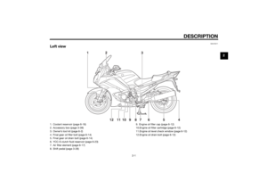 13
13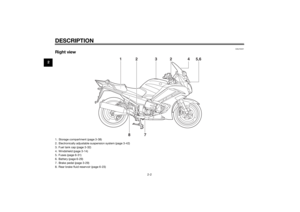 14
14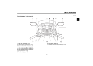 15
15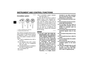 16
16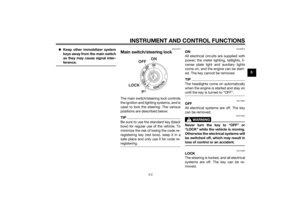 17
17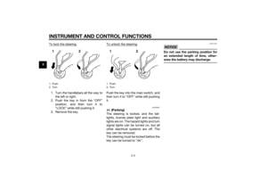 18
18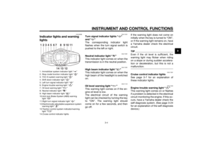 19
19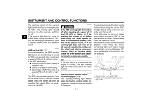 20
20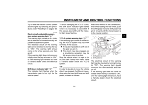 21
21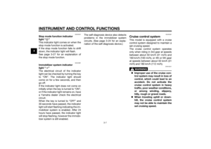 22
22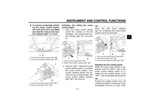 23
23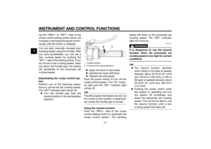 24
24 25
25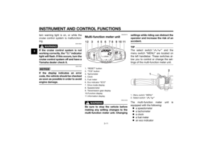 26
26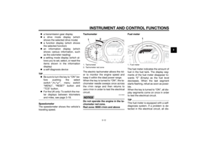 27
27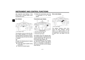 28
28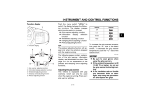 29
29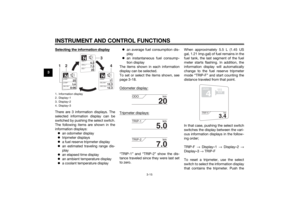 30
30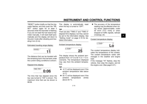 31
31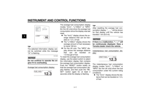 32
32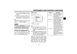 33
33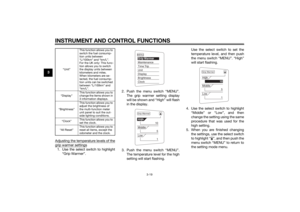 34
34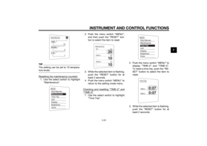 35
35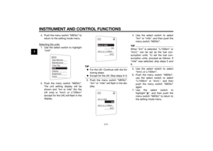 36
36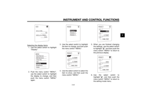 37
37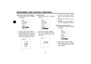 38
38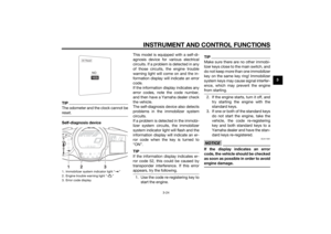 39
39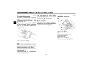 40
40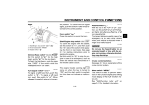 41
41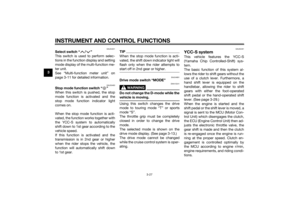 42
42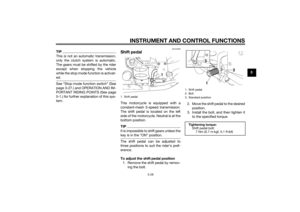 43
43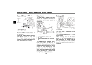 44
44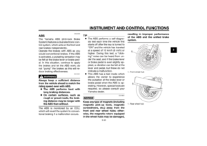 45
45 46
46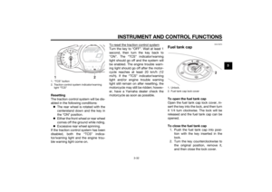 47
47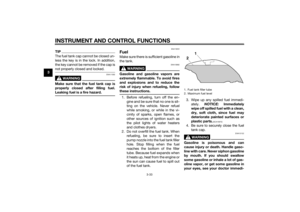 48
48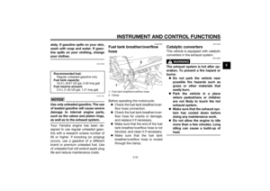 49
49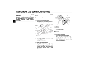 50
50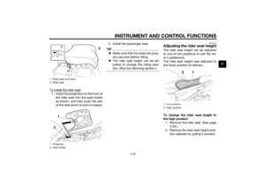 51
51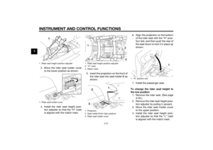 52
52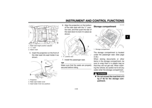 53
53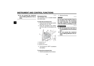 54
54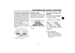 55
55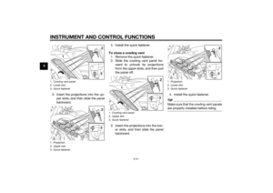 56
56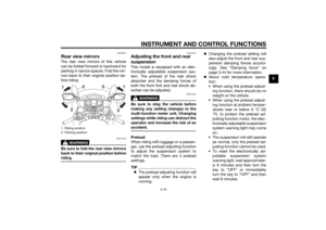 57
57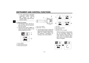 58
58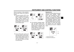 59
59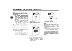 60
60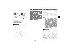 61
61 62
62 63
63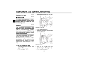 64
64 65
65 66
66 67
67 68
68 69
69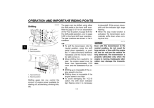 70
70 71
71 72
72 73
73 74
74 75
75 76
76 77
77 78
78 79
79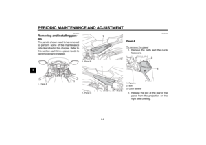 80
80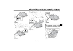 81
81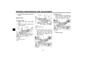 82
82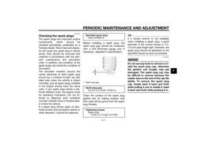 83
83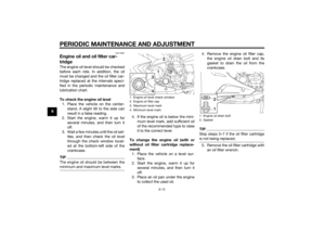 84
84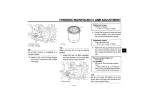 85
85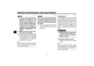 86
86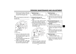 87
87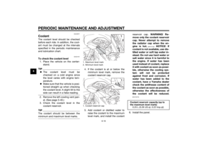 88
88 89
89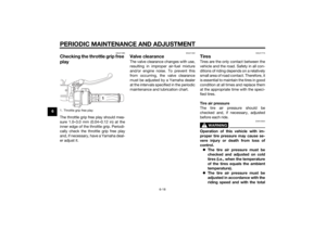 90
90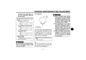 91
91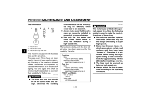 92
92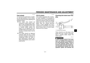 93
93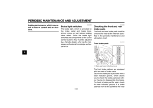 94
94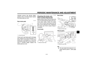 95
95 96
96 97
97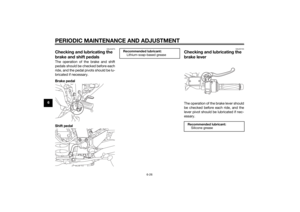 98
98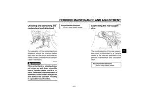 99
99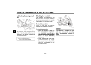 100
100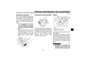 101
101 102
102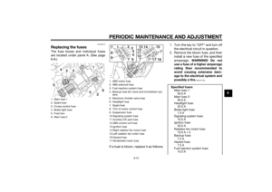 103
103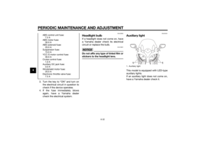 104
104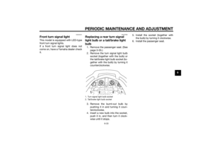 105
105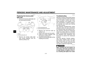 106
106 107
107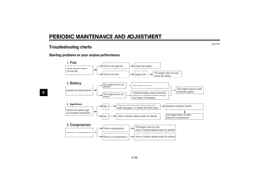 108
108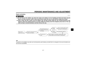 109
109 110
110 111
111 112
112 113
113 114
114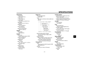 115
115 116
116 117
117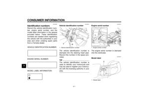 118
118 119
119 120
120 121
121 122
122 123
123

 for the ve-
hicle.
EAU39481
Accessory boxThe accessory box is located beside
the meter panel.
To open the ac")
