2015 VAUXHALL MOVANO_B engine
[x] Cancel search: enginePage 126 of 209

124Driving and operating
Press the Ø button. LED illuminates
in button and a corresponding message appears in the Driver
Information Centre 3 84.
TC is reactivated by pressing the Ø
button again. LED extinguishes in
button. TC is also reactivated the next time the ignition is switched on.
When vehicle speed reaches
30 mph the TC function will be
restored automatically.
Fault
If the system detects a fault, control indicator A 3 80 illuminates in the
instrument cluster and a
corresponding message appears in
the Driver Information Centre 3 84.
Have the cause of the fault remedied by a workshop.
Vehicle messages 3 85.
Electronic stability
program
The Electronic stability program
(ESP® Plus
) improves driving stability
when necessary, regardless of thetype of road surface or tyre grip. It also
prevents the drive wheels from
spinning.
As soon as the vehicle starts to
swerve (understeer/oversteer),
engine output is reduced and the
wheels are braked individually. This
considerably improves the driving
stability of the vehicle on slippery road
surfaces.
ESP® Plus
is operational as soon as
the ignition is switched on and control
indicator b extinguishes in the
instrument cluster.
When ESP® Plus
comes into action b
flashes.9 Warning
Do not let this special safety
feature tempt you into taking risks
when driving.
Adapt speed to the road
conditions.
Control indicator b 3 81.
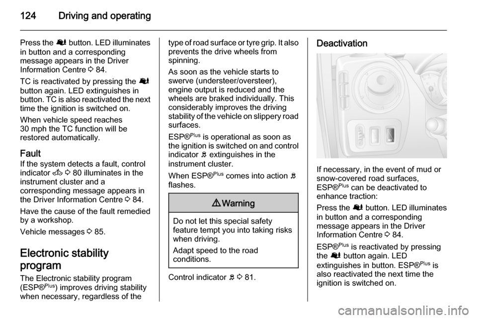
Deactivation
If necessary, in the event of mud or
snow-covered road surfaces,
ESP® Plus
can be deactivated to
enhance traction:
Press the Ø button. LED illuminates
in button and a corresponding
message appears in the Driver
Information Centre 3 84.
ESP® Plus
is reactivated by pressing
the Ø button again. LED
extinguishes in button. ESP® Plus
is
also reactivated the next time the
ignition is switched on.
Page 132 of 209

130Driving and operatingRear view camera
The camera is typically installed
under the number plate moulding with a display monitor fitted to the driver's
sun visor.
Functionality
The rear view camera system
enables the driver to view the rear of
the vehicle in the display monitor
whilst reversing.
The system can be activated or
deactivated by selecting the
Start/Stop button located on the right-
hand side of the display monitor.
The remaining buttons on the monitor enable the user to select source
AV1 or AV2 and adjust the brightness
and contrast of the display monitor.
To achieve the optimum visibility, the
rear view camera must not be
obscured by dirt, snow or ice.9 Warning
The system is intended as a
reversing aid and does not replace
driver vision.
Do not let this feature tempt you
into take risks when reversing.
Failure to use proper care when
reversing may result in damage to
the vehicle, injury, or death.
Always check the outside,
rearview mirrors and glance over
your shoulder before reversing.
The driver assistance systems do not relieve the driver from full
responsibility for vehicle
operation.
Fuel
Fuel for diesel enginesOnly use diesel fuel that complies
with EN 590. The fuel must have low
sulphur content (max. 10 ppm).
Equivalent standardised fuels with a
biodiesel (= FAME according to
EN14214) content of max. 7% by
volume (like DIN 51628 or equivalent
standards) may be used.
In countries outside the European
Union use Euro-Diesel fuel with a
sulphur concentration below 50 ppm.Caution
Use of fuel that does not comply to EN 590 or similar can lead to
engine powerloss, increased wear
or engine damage and may affect
your warranty.
Do not use marine diesel oils, heating
oils or entirely plant-based diesel
fuels, such as rape seed oil or bio
Page 133 of 209

Driving and operating131
diesel, Aquazole and similar diesel-
water emulsions. Diesel fuels must not be diluted with fuels for petrol
engines.
The flow and filterability of diesel fuels are temperature-dependent. When
temperatures are low, refuel with
diesel fuel with guaranteed winter
properties.
Refuelling9 Danger
Before refuelling, switch off engine
and any external heaters with
combustion chambers. Switch off
any mobile phones.
Follow the operating and safety
instructions of the filling station
when refuelling.
9 Danger
Fuel is flammable and explosive.
No smoking. No naked flames or
sparks.
If you can smell fuel in your
vehicle, have the cause of this
remedied immediately by a
workshop.Caution
In case of misfuelling, do not
switch on ignition.
The fuel tank filler neck with bayonet
cap is located on the left front side of
the vehicle.
The fuel filler flap can only be opened
if the vehicle is unlocked and the door is opened. Open the fuel filler flap by
hand.
Remove the fuel filler cap by turning
it anti-clockwise.
The fuel filler cap can be hung on the lower hook of the fuel filler flap.
Caution
Wipe off any overflowing fuel
immediately.
When refuelling is complete, replace
the filler cap and turn it clockwise.
Close the fuel filler flap.
Page 135 of 209

Driving and operating133
If the trailer starts snaking, drive moreslowly, do not attempt to correct the
steering and brake sharply if
necessary.
When driving downhill, drive in the
same gear as if driving uphill and
drive at a similar speed.
Adjust tyre pressure to the value
specified for full load 3 198.
Trailer towing Trailer loads
The permissible trailer loads are
vehicle-dependent and engine-
dependent maximum values which
must not be exceeded. The actual
trailer load is the difference between
the actual gross weight of the trailer
and the actual coupling socket load
with the trailer coupled.
The permissible trailer loads are
specified in the vehicle documents. In general, they are valid for gradients
up to max. 12 %.
The permitted trailer load applies up to the specified incline and up to an
altitude of 1000 metres above sealevel. Since engine power decreases as altitude increases due to the airbecoming thinner, therefore reducing
climbing ability, the permissible gross
train weight also decreases by 10 % for every 1000 metres of additional
altitude. The gross train weight does
not have to be reduced when driving on roads with slight inclines (less than 8 %, e.g. motorways).
The permissible gross train weight
must not be exceeded. This weight is
specified on the identification plate
3 179.
Vertical coupling load
The vertical coupling load is the load
exerted by the trailer on the coupling
ball. It can be varied by changing the
weight distribution when loading the
trailer.
The maximum permissible vertical
coupling load is specified on the
towing equipment identification plate
and in the vehicle documents. Always aim for the maximum load, especially
in the case of heavy trailers. The
vertical coupling load should never
fall below 25 kg.In the case of trailer loads of
1200 kg or more, the vertical coupling load should not be less than 50 kg.
Rear axle load When the trailer is coupled and the
towing vehicle fully loaded (including
all occupants), the permissible rear
axle load (see identification plate or
vehicle documents) must not be
exceeded.
Towing equipmentCaution
When operating without a trailer,
remove the coupling ball bar.
Towing equipment audible
warning For vehicles fitted with towing
equipment, when connected to a
trailer the pitch of the audible warning
changes upon operation of the turn
signals.
Page 136 of 209

134Driving and operating
The pitch of the audible warning will
change if a turn signal light on the
trailer or the towing vehicle fails.
Trailer stability assist
If the system detects snaking
movements, engine power is reduced
and the vehicle/trailer combination is
selectively braked until the snaking ceases. While the system is working,keep steering wheel as still as
possible.
Trailer stability assist (TSA) is a
function of the Electronic stability
program (ESP) 3 124.Auxiliary features
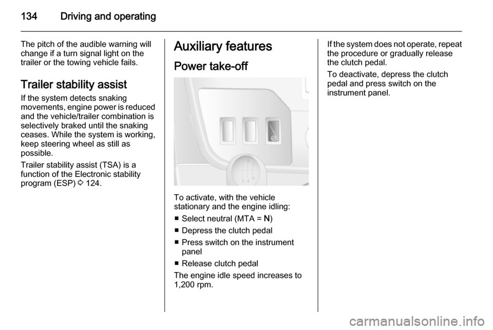
Power take-off
To activate, with the vehicle
stationary and the engine idling:
■ Select neutral (MTA = N)
■ Depress the clutch pedal
■ Press switch on the instrument panel
■ Release clutch pedal
The engine idle speed increases to 1,200 rpm.
If the system does not operate, repeat
the procedure or gradually release
the clutch pedal.
To deactivate, depress the clutch
pedal and press switch on the
instrument panel.
Page 137 of 209

Vehicle care135Vehicle careGeneral Information...................135
Vehicle checks ........................... 136
Bulb replacement .......................144
Electrical system ........................152
Vehicle tools .............................. 155
Wheels and tyres .......................156
Jump starting ............................. 168
Towing ....................................... 170
Appearance care .......................171General Information
Accessories and vehicle
modifications
We recommend the use of genuine parts and accessories and factory
approved parts specific for your
vehicle type. We cannot assess or
guarantee reliability of other products
- even if they have a regulatory or
otherwise granted approval.
Do not make any modifications to the electrical system, e.g. changes of
electronic control units (chip tuning).Caution
When transporting the vehicle on
a train or on a recovery vehicle, the
mud flaps might be damaged.
Vehicle storage
Storage for a long period of time
If the vehicle is to be stored for several months:
■ Wash and wax the vehicle.
■ Have the wax in the engine compartment and underbody
checked.
■ Clean and preserve rubber seals.
■ Change engine oil.
■ Drain washer fluid reservoir.
■ Check coolant antifreeze and corrosion protection.
■ Adjust tyre pressure to the value specified for full load.
■ Park vehicle in a dry, well ventilated
place. Engage first or reverse gear.
Prevent the vehicle from rolling.
■ Do not apply parking brake.
Page 138 of 209

136Vehicle care
■ Open bonnet, close all doors andlock the vehicle.
■ Disconnect the clamp from the negative terminal of the vehicle
battery. Beware that all systems are not functional, e.g. anti-theft alarm
system.
Putting back into operation When the vehicle is to be put back into
operation:
■ Connect the clamp to the negative terminal of the vehicle battery.
Activate the electronics of the
power windows.
■ Check tyre pressure.
■ Fill up the washer fluid reservoir.
■ Check the engine oil level.
■ Check the coolant level.
■ Fit the number plate, if necessary.End-of-life vehicle
recovery
Information on end-of-life vehicle
recovery centres and the recycling of
end-of-life vehicles is available on our website, where legally required. Only
entrust this work to an authorised
recycling centre.Vehicle checks
Performing work9 Warning
Only perform engine compartment
checks when the ignition is off.
The cooling fan may start
operating even if the ignition is off.
9 Danger
The ignition system generates
extremely high voltages. Do not
touch.
The caps for topping up the engine oil, the coolant, the washer fluid and the
oil dipstick handle are yellow for ease
of identification.
Page 139 of 209

Vehicle care137Bonnet
Opening
Pull the release lever and return it to
its original position.
Pull the safety catch, located slightly
left of centre, and open the bonnet.
Pull up the support rod from its holder,
then secure it in the right side hook on the underside of the bonnet.
If the bonnet is opened during an Autostop, the engine will be restarted
automatically for safety reasons.
Closing
Before closing the bonnet, press the
support into the holder.
Lower the bonnet and allow it to drop into the catch. Check that the bonnet
is engaged.
Engine oil
Check the engine oil level manually
on a regular basis to prevent damage
to the engine.
Ensure that the correct specification
of oil is used. Recommended fluids
and lubricants 3 176.
Check with the vehicle on a level
surface. The engine must be at
operating temperature and switched
off for at least 10 minutes.