2015 VAUXHALL MOVANO_B suspension
[x] Cancel search: suspensionPage 40 of 209

38Seats, restraintsSeat adjustment9Danger
Do not sit nearer than 25 cm from
the steering wheel, to permit safe
airbag deployment.
9 Warning
Never adjust seats while driving as
they could move uncontrollably.
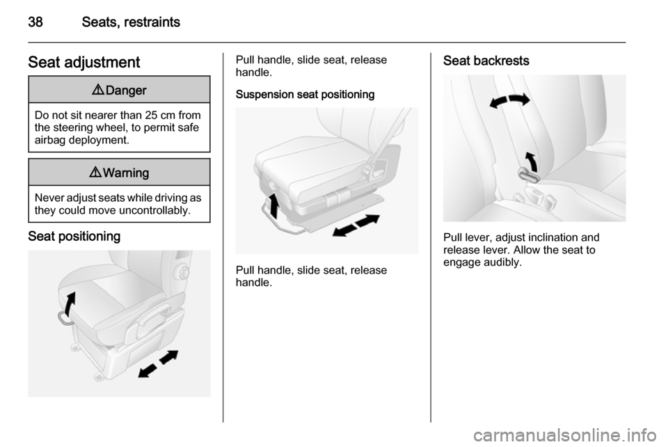
Seat positioning
Pull handle, slide seat, release
handle.
Suspension seat positioning
Pull handle, slide seat, release
handle.
Seat backrests
Pull lever, adjust inclination and
release lever. Allow the seat to
engage audibly.
Page 41 of 209

Seats, restraints39
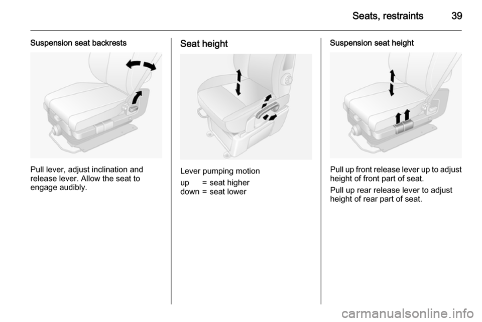
Suspension seat backrests
Pull lever, adjust inclination and
release lever. Allow the seat to
engage audibly.
Seat height
Lever pumping motion
up=seat higherdown=seat lowerSuspension seat height
Pull up front release lever up to adjust height of front part of seat.
Pull up rear release lever to adjust height of rear part of seat.
Page 42 of 209

40Seats, restraints
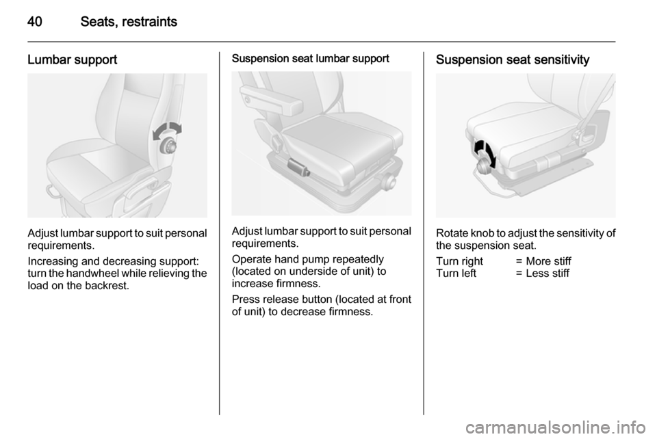
Lumbar support
Adjust lumbar support to suit personalrequirements.
Increasing and decreasing support:
turn the handwheel while relieving the load on the backrest.
Suspension seat lumbar support
Adjust lumbar support to suit personal requirements.
Operate hand pump repeatedly
(located on underside of unit) to
increase firmness.
Press release button (located at front
of unit) to decrease firmness.
Suspension seat sensitivity
Rotate knob to adjust the sensitivity of the suspension seat.
Turn right=More stiffTurn left=Less stiff
Page 116 of 209

114Driving and operating■ Always apply parking brakewithout pressing release button.Apply as firmly as possible on a
downhill slope or uphill slope.
Depress foot brake at the same
time to reduce operating force.
■ Switch off the engine.
■ If the vehicle is on a level surface or uphill slope, engage
first gear. On an uphill slope,
turn the front wheels away from the kerb.
If the vehicle is on a downhill
slope, engage reverse gear.
Turn the front wheels towards
the kerb.
Lock the vehicle 3 19 and activate the
anti-theft locking system 3 27 and
anti-theft alarm system 3 27.
Air suspension Operates automatically when the
vehicle is driven. The air suspension
system constantly adjusts the ride
height according to the vehicle load.
For further information on the air
suspension system, refer to the
operating instructions supplied.
Master switchCaution
The air suspension system must
be switched off when the vehicle is
being towed, jump‐started, raised
off the ground or transported.
Do not switch off the air
suspension system when driving.
The master switch is located on the
door pillar.
Remote control
When increased ground clearance or improved vehicle access is required,the suspension can be raised or
lowered using the remote control.
The remote control unit is magnetic
and can be fixed to any metal part of
the vehicle.
With the ignition switched on, press
the appropriate button for 2 seconds
to adjust the suspension height.
Page 117 of 209

Driving and operating115
Indicator light will flash intermittently
while height adjustment is in progress
and illuminates when complete.
Handle with care, protect from
moisture and high temperatures and
avoid unnecessary operation.
Pre-programmed settings Adjusts the suspension height to oneof three pre-programmed positions.
The buttons are only functional when
the engine is running.l=lowered positionk=normal positionj=raised position
Manual settings
Manual adjustment can only be
performed when the vehicle is
stationary.
Select by pressing button h for 2
seconds, then button R to raise, or
button S to lower.
To exit, press any of the pre-
programmed buttons.
When the vehicle is moving, manual
adjustment will exit automatically. If
the ignition is switched off, the vehicle will return to normal ride height when
the ignition is switched back on.
Service mode Press button i for 5 seconds to put
the vehicle into service mode. The
indicator light will illuminate. When
service mode has been activated, the
air suspension master switch must be turned off.
To exit service mode, press button
i again for 5 seconds.
Fault If a fault is detected, i button will
flash intermittently. If the service
mode has been activated and there is a fault h, S and R buttons will flash
simultaneously.
Have the cause of the fault remedied by a workshop.Engine exhaust9 Danger
Engine exhaust gases contain
poisonous carbon monoxide,
which is colourless and odourless and could be fatal if inhaled.
If exhaust gases enter the interior
of the vehicle, open the windows.
Have the cause of the fault
rectified by a workshop.
Avoid driving with an open load
compartment, otherwise exhaust
gases could enter the vehicle.
Diesel particle filter
The diesel particle filter system filters
harmful soot particles out of the
exhaust gases. The system includes
a self-cleaning function that runs
automatically during driving without
any notification. The filter is cleaned
by periodically burning off the soot
particles at high temperature. This
Page 166 of 209

164Vehicle care
not be driven. Seek the
assistance of a workshop.
20. Stow tyre repair kit under the front
seat.
Notice
The driving characteristics of the repaired tyre are severely affected,
therefore have this tyre replaced.
If unusual noise is heard or the
compressor becomes hot, turn
compressor off for at least
30 minutes.
The built-in safety valve opens at a
pressure of 7 bar (102 psi).
Note the expiry date of the kit. After
this date its sealing capability is no
longer guaranteed. Pay attention to
storage information on sealant
bottle.
Replace the used sealant bottle. Dispose of the bottle as prescribed
by applicable laws.
The compressor and sealant can be
used from approx. -30 °C.
The adapters supplied can be used
to pump up other items e.g.
footballs, air mattresses, inflatabledinghies etc. They are located on the underside of the compressor. To
remove, screw on compressor air
hose and withdraw adapter.
Wheel changing Some vehicles are equipped with a
tyre repair kit instead of a spare wheel 3 161.
Make the following preparations and
observe the following information:
■ Park the vehicle on a level, firm and
non-slippery surface. The front wheels must be in the straight-ahead position.
■ Apply the parking brake and engage first gear or reverse gear.
■ Switch off the air suspension system 3 114.
■ Remove the spare wheel 3 166.
■ Never change more than one wheel
at a time.
■ Use the jack only to change wheels
in case of puncture, not for
seasonal winter or summer tyre
change.
■ The jack is maintenance-free.■ If the ground on which the vehicle is standing is soft, a solid board
(max. 1 cm thick) should be placed
under the jack.
■ No people or animals may be in the
vehicle when it is jacked-up.
■ Never crawl under a jacked-up vehicle.
■ Do not start the engine when the vehicle is raised on the jack.
■ Clean wheel bolts/nuts and their threads before mounting the wheel.9 Warning
Do not grease wheel bolt, wheel
nut and wheel nut cone.
1. Remove the wheel cover using the hook supplied. Vehicle tools
3 155.
2. Install the wheel wrench ensuring that it locates securely and loosen
each wheel bolt/nut by half a turn.
Page 170 of 209

168Vehicle care
If your vehicle gets a flat tyre on therear while towing another vehicle,
mount the temporary spare wheel in the front and the full tyre in the rear.
Tyre chains 3 161.
Summer and winter tyres
If you use winter tyres, the spare
wheel may still be fitted with a
summer tyre.
If you use the spare wheel when it is
fitted with a summer tyre the vehicle's
driveability may be affected,
especially on slippery road surfaces.
Directional tyres Fit directional tyres such that they rollin the direction of travel. The rolling
direction is indicated by a symbol
(e.g. an arrow) on the sidewall.
The following applies to tyres fitted
opposing the rolling direction:
■ Driveability may be affected. Have the defective tyre renewed or
repaired as soon as possible.
■ Do not drive faster than 50 mph.
■ Drive particularly carefully on wet and snow-covered road surfaces.Jump starting
Do not start with a quick charger.
A vehicle with a discharged battery
can be started using jump leads and
the battery of another vehicle.9 Warning
Be extremely careful when starting
with jump leads. Any deviation
from the following instructions can
lead to injuries or damage caused
by battery explosion or damage to the electrical systems of both
vehicles.
9 Warning
Avoid contact with eyes, skin,
fabrics, and painted surfaces. The fluid contains sulphuric acid which can cause injuries and damage in
the event of direct contact.
Caution
The air suspension system must
be switched off prior to jump
starting.
9 Warning
Avoid contact of the battery with
eyes, skin, fabrics and painted
surfaces. The fluid contains
sulphuric acid which can cause
injuries and damage in the event
of direct contact.
■ Never expose the vehicle battery to
naked flames or sparks.
■ A discharged vehicle battery can already freeze at a temperature of
0 °C. Defrost the frozen vehicle
battery before connecting jump
leads.
■ Wear eye protection and protective
clothing when handling a vehicle
battery.
Page 171 of 209

Vehicle care169
■ Use a booster battery with thesame voltage (12 volts). Its capacity
(Ah) must not be much less than
that of the discharged vehicle
battery.
■ Use jump leads with insulated terminals and a cross section of at
least 25 mm 2
.
■ Do not disconnect the discharged battery from the vehicle.
■ Switch off all unnecessary electrical
consumers.
■ Switch off the air suspension system.
■ Do not lean over the vehicle battery
during jump starting.
■ Do not allow the terminals of one lead to touch those of the otherlead.
■ The vehicles must not come into contact with each other during the
jump starting process.
■ Apply the parking brake, transmission in neutral.Jump start terminal
In the event of a discharged vehicle
battery, the jump start terminal
enables the vehicle to be started
without the need to access the battery inside the vehicle.
The jump start terminal is located in
the engine compartment and
identified by a " <" sign on the red
insulating cover. Lift the red insulating
cover to access the terminal
connector.
Ensure the red insulating cover is
latched back into position when not in
use.
Jump starting procedure
Lead connection order:
1. Connect the red lead to the positive terminal of the booster
battery.
2. Connect the other end of the red lead to the jump start terminal of
the vehicle with the discharged
vehicle battery.
3. Connect the black lead to the negative terminal of the booster
battery.
4. Connect the other end of the black
lead to a vehicle grounding point,
such as the engine block or an