Page 137 of 160

CAUTIONÔľáÔÇťNever repairÔÇŁ fuses and also do not replace them with a fuse of a higher am-
perage ÔÇô risk of fire! This may also cause damage at another part of the electri-
cal system.Ôľá
If a newly inserted fuse blows again after a short time, have the electrical
system checked as quickly as possible by a specialist garage.
Ôľá
A blown fuses is recognisable by the molten metal strip. Replace the faulty
fuse with a new one of the same amperage.
Note
Ôľá
We recommend always carrying replacement fuses in the vehicle. A box of
replacement fuses and bulbs can be purchased from ŠKODA Original Accesso-
ries.Ôľá
There can be several power consuming devices for one fuse.
Ôľá
Multiple fuses may exist for a single power consuming device.
Fuses in the dash panel
Fig. 134
Remove the fuse box cover.
Read and observe and on page 134 first.
The fuses are located underneath the steering wheel on the underside of the dash panel ┬╗ Fig. 134.
Replacing fuses
ÔÇ║
Press securing tab
A
┬╗ Fig. 134 .
ÔÇ║
Push the lid in the direction of the arrow.
ÔÇ║
Remove bracket
B
.
ÔÇ║
Place the bracket on the respective fuse and pull this out.
ÔÇ║
Insert a new fuse.
ÔÇ║
Replace the bracket at the original position.
ÔÇ║
Fold the cover upwards against the direction of the arrow.
ÔÇ║
Close the cover until it clicks into place.
´âĄFuse allocation in the dash panelFig. 135
Fuses
Read and observe and on page 134 first.
No.Consumer1Air Conditioning, diagnostic connector2Headlight range control, park assist, electric exterior mirror adjust-
ment3Automatic transmission, engine control unit, power steering, control
lever under the steering wheel, instrument cluster4Airbag5Reversing light6Rear wiper, windscreen washer system7Main beam headlamp - left side8Main beam headlamp - right side9Not assigned10Electric exterior mirror heater11Not assigned12Vehicle lighting13Vehicle lighting14Vehicle lighting15Vehicle with START-STOPsystem: Radio
Vehicle without START-STOPsystem: Central Control Unit, heating,
automatic transmission, light switch, license plate light16Vehicle lighting17Rear window wiper18Panoramic sunroof ´éú´âĄ135Fuses and light bulbs
Page 138 of 160

No.Consumer19Central locking system20Rear window heater21Reversing light22Horn23Voltage transformer24Headlamp flasher25Windscreen wipers26Radio27Turn signal lights, brake lights28Selector lever for the automatic transmission29Fuel pump30Engine control unit, instrument cluster, central control unit, rain sen-
sor, control lever under the steering wheel, diagnostic connector31Vehicle lighting32Central control unit33Vehicle lighting34Indoor lighting35Vehicle lighting36Vehicle lighting37ESC38Key bar39Lever under the steering wheel, windscreen washer system40Engine components41Brake pedal switch, cooling fan42Engine control unit43Fuel pump44Engine components45Engine components4612-volt power socket47Air blower for air conditioning/heating48Seat heaters49Electric power windowsNo.Consumer50Vehicle lighting51Electric power windows
Fuses in the dash panel
Fig. 136
Remove the fuse box cover.
Read and observe and on page 134 first.
On vehicles with the START-STOPsystem, the fuses are on the left side of the
dash panel behind a cover.
Replacing fuses
ÔÇ║
Insert a slotted screwdriver into the recess
A
in the cover ┬╗ Fig. 136.
ÔÇ║
Loosen the cover and remove in the direction of the arrow.
ÔÇ║
Replace the appropriate fuse.
ÔÇ║
Close the cover until it clicks into place.
´âĄ136Do-it-yourself
Page 139 of 160

Assignment of the fuses in the dash panelFig. 137
Fuses
Read and observe and on page 134 first.
No.Consumer1ABS/ESP2Instrument cluster3Radio4DC-DC voltage converter, starter relay, bar with buttons5Air conditioning system6Not assigned7Not assigned8Not assigned9Vehicle lighting - right side10Vehicle lighting - left side11Starter12DC-DC voltage converter, ABS, instrument cluster, radio´âĄFuses in the engine compartmentFig. 138
Remove the fuse box cover.
Read and observe and on page 134 first.
The fuses are located underneath a cover next to the vehicle battery
┬╗ Fig. 138 .
Replacing fuses
ÔÇ║
Press the locking keys
1
of the cover ┬╗ Fig. 138 together simultaneously.
ÔÇ║
Push the cover in the direction of the arrow
2
.
ÔÇ║
Replace the appropriate fuse.
ÔÇ║
Insert the cover in the direction counter to the arrow.
ÔÇ║
Close the cover until it clicks into place.
Fuse allocation in the engine compartment
Fig. 139
Fuses
Read and observe and on page 134 first.
No.Consumer1ABS/ESP2Radiator fan ´éú´âĄ´âĄ137Fuses and light bulbs
Page 140 of 160

No.Consumer3Control unit for radiator fan, ignition4ABS/ESP5Central control unit, battery data module6Ignition lock, starter
Replacing bulbs
´âĄIntroduction
This chapter contains information on the following subjects:
Bulb arrangement in the headlights
138
Changing the low beam and high beam bulb (halogen headlights)
139
Replacing bulb for daytime running lights and parking lights
139
Changing the front turn signal bulb
139
Replacing the bulb for the fog light
140
Replacing the bulb for the licence plate light
140
Rear Light
141
Changing a bulb in the tail light
141
Some manual skills are required to change a bulb. For this reason, we recom-
mend having bulbs replaced by a specialist garage or seeking other expert help
in the event of any uncertainties.
Ծ Switch off the ignition and all of the lights before replacing a bulb.
Ծ Faulty bulbs must only be replaced with the same type of bulbs. The designa-
tion is located on the light socket or the glass bulb.
Ծ A stowage compartment for replacement bulbs is located in a plastic box in
the spare wheel or underneath the floor covering in the luggage compart-
ment.
Depending on the vehicle design, some vehicles may be equipped with LED
daytime running lights in the front bumper instead of the fog lights.
WARNINGÔľá Always read and observe the warnings before completing any work in the
engine compartment ┬╗ page 106.Ôľá
Accidents can be caused if the road in front of the vehicle is not suffi-
ciently illuminated and the vehicle cannot or can only be seen with difficul-
ty by other road users.
Ôľá
The H4 bulb is pressurised and may explode during a bulb replacement -
risk of injury! We therefore recommended wearing gloves and safety
glasses when changing a bulb.
Ôľá
Switch off the respective vehicle light when changing the bulb.
CAUTION
Do not take hold of the glass bulb with naked fingers (even the smallest
amount of dirt reduces the working life of the light bulb). Use a clean cloth,
napkin, or similar.
Note
Ôľá This Owner's Manual only describes the replacement of bulbs where it is pos-
sible to replace the bulbs on your own without any complications arising. Other
bulbs must be replaced by a specialist garage.Ôľá
We recommend that a box of replacement bulbs always be carried in the ve-
hicle. Replacement bulbs can be purchased from ŠKODAOriginal Accessories.
Ôľá
We recommend having the headlight settings checked by a specialist garage
after replacing a bulb in the main beam, low beam or fog lights.
Ôľá
If the LED diode is defect visit a specialist garage.
Bulb arrangement in the headlights
Fig. 140
Principle sketch: Headlights
Read and observe and on page 138 first.
The vehicle is equipped with headlights with halogen bulbs. ´éú
´âĄ138Do-it-yourself
Page 141 of 160

Fig. 141
Replacing the bulb for low beam a")
Bulb arrangement ┬╗ Fig. 140
Flashing
Low beam and high beam
Daytime running and parking light
Changing the low beam and high beam bulb (halogen headlights)
Fig. 141
Replacing the bulb for low beam and main beam
Read and observe
and on page 138 first.
ÔÇ║
Remove the connector from the bulb in the direction of arrow
1
┬╗ Fig. 141 .
ÔÇ║
Remove the protective cap
A
.
ÔÇ║
Press the safety catch in the direction of the headlamp and then unhook in
the direction of arrow
2
┬╗ Fig. 141 .
ÔÇ║
Open out the safety catch in the direction of arrow
3
.
ÔÇ║
Remove the light bulb in the direction of arrow
4
and insert a new light bulb
in such a way that the fixing lugs of the light bulb socket fit into the recesses
of the lamp.
Installation is carried out in the reverse order.
ABC´âĄReplacing bulb for daytime running lights and parking lightsFig. 142
Replacing the bulb for daytime
running lights and parking lights
Read and observe and on page 138 first.
ÔÇ║
Turn the housing containing the bulb
C
┬╗ Fig. 140 on page 138 as far as the
stop in the direction of the arrow
1
┬╗ Fig. 142 .
ÔÇ║
Remove the housing containing the bulb in the direction of arrow
2
.
ÔÇ║
Remove the faulty bulb from the housing.
ÔÇ║
Insert a new bulb into the housing.
ÔÇ║
Insert the housing containing the light bulb in the lamp housing in the oppo-
site direction to arrow
2
.
ÔÇ║
Screw the housing in the opposite direction to arrow
1
until it clicks into
place.
Changing the front turn signal bulb
Fig. 143
Changing the bulb for the front
turn signal light
Read and observe and on page 138 first.
ÔÇ║
Turn the housing containing the bulb
A
┬╗ Fig. 140 on page 138 as far as the
stop in the direction of the arrow
1
┬╗ Fig. 143 .
ÔÇ║
Remove the housing containing the bulb in the direction of arrow
2
.´éú
´âĄ´âĄ139Fuses and light bulbs
Page 142 of 160

ÔÇ║Unscrew the defective bulb in its housing in an
anti-clockwise direction and
remove it.ÔÇ║
Place a new bulb in the housing and turn it in a clockwise direction as far as
it will go.
ÔÇ║
Insert the housing containing the light bulb in the lamp housing in the oppo-
site direction to arrow
2
.
ÔÇ║
Screw the housing in the opposite direction to arrow
1
until it clicks into
place.
Replacing the bulb for the fog light
Fig. 144
Removing the wheel house trim
Fig. 145
Changing a bulb
Read and observe
and on page 138 first.
Removing the wheel house trim
ÔÇ║
Use the on board tool to remove screws
A
┬╗ Fig. 144 from the wheel well.
ÔÇ║
Using a flat, blunt object, e.g. a coin, turn the part of the expansion rivet with
a slit 90 degrees in the direction of arrow
1
.
´âĄÔÇ║ Pull out the part of the expansion rivet with a slit in the direction of arrow2 .ÔÇ║
Take out the expansion rivet in the direction of the arrow
3
.
Changing a bulb
ÔÇ║
Open out the wheel house trim in the direction of arrow
4
┬╗ Fig. 145 .
ÔÇ║
Press in the locking for the connector in the direction of arrow
5
.
ÔÇ║
Remove the connector in the direction of the arrow
6
.
ÔÇ║
Screw the lamp connector in the direction of the arrow
7
as far as the stop.
ÔÇ║
Remove the lamp connector in the direction of the arrow
8
.
ÔÇ║
Place a new connector with the bulb in the headlamp and turn it in the direc-
tion of arrow
7
as far as the stop.
ÔÇ║
Attach the connector until it clicks firmly into place.
Fitting the wheel house trim
ÔÇ║
Fold the wheel house trim back.
ÔÇ║
Push the expansion rivet back in.
ÔÇ║
Push in the part of the expansion rivet with a slit
2
and turn it 90 degrees in
the opposite direction to arrow
1
┬╗ Fig. 144 .
ÔÇ║
Firmly tighten the two attachment bolts
A
with the screwdriver.
Replacing the bulb for the licence plate light
Fig. 146
Removing the licence plate lamp
Read and observe
and on page 138 first.
ÔÇ║
Insert a slotted screwdriver into the slot in area
A
┬╗ Fig. 146 and free up the
lamp in the direction of arrow
1
.
ÔÇ║
Remove the lamp from the bumper.
ÔÇ║
Unscrew the lamp in the direction of arrow
2
and remove it in the direction
of arrow
3
.
ÔÇ║
Remove the faulty bulb from the housing. ´éú
´âĄ140Do-it-yourself
Page 143 of 160

ÔÇ║Insert a new bulb into the housing.ÔÇ║Insert the housing with the bulb in the lamp and turn it in the opposite direc-
tion to arrow 2
as far as the stop.
ÔÇ║
Insert the lamp into area
A
into the bumper opening and press lightly until
the spring locks into place.
CAUTION
Ensure that the vehicle paintwork and the tail lamp are not damaged when re-
moving and installing the tail lamp.
Rear Light
Fig. 147
Removing lamp / connector
Read and observe
and on page 138 first.
Removing lamp
ÔÇ║
Open the boot lid.
ÔÇ║
Fold the rear seat backrest forward ┬╗ page 57, Seat backrests .
ÔÇ║
Remove the boot cover ┬╗ page 66.
ÔÇ║
Open up the flap in area
A
in the direction of arrow
1
┬╗ Fig. 147 .
ÔÇ║
Insert the screwdriver under the bottom edge of the locking mechanism
B
┬╗ page 122 , Vehicle tool kit and pull out the locking mechanism on the con-
nector in the direction of arrow
2
.
ÔÇ║
Press the catch
C
in the direction of arrow
3
.
ÔÇ║
Pull out the connector in the direction of the arrow
4
.
ÔÇ║
Hold the lamp firmly and unscrew the plastic nut
D
.
ÔÇ║
Carefully remove the light from the body and place it on a clean, smooth sur-
face.
Fitting the lamp
ÔÇ║
Insert the bulb holder in the light.
´âĄÔÇ║ Carefully place the tail light assembly in the opening in the body and hold
firmly.ÔÇ║
Screw in and tighten the plastic nut
D
┬╗ Fig. 147 .
ÔÇ║
Push the connector into the bulb holder and press down on the catch
B
in
the opposite direction to arrow
2
.
ÔÇ║
Fold back the cover in the opposite direction to arrow
1
.
ÔÇ║
Install the luggage compartment cover and close the tailgate.
Fold the rear seat backrest back.
CAUTION
Ensure that the vehicle paintwork and the tail lamp are not damaged when re-
moving and installing the lamp.
Changing a bulb in the tail light
Fig. 148
Inner part of the lamp
Read and observe
and on page 138 first.
Changing a bulb
ÔÇ║
Unhook the bulb holder ┬╗ Fig. 148 - ´âł
.
ÔÇ║
Take the holder out of the lamp assembly.
ÔÇ║
Unscrew the defective bulb in its housing in an anti-clockwise direction and
remove it ┬╗ Fig. 148 - ´âë
.
ÔÇ║
Place a new bulb in the housing and turn it in a clockwise direction as far as
it will go.
´âĄ141Fuses and light bulbs
Page 144 of 160

Technical data
Technical data
Basic vehicle data
´âĄIntroduction
This chapter contains information on the following subjects:
Vehicle characteristics
142
Operating weight
143
Payload
143
Measurement of fuel consumption and CO 2 emissions according to ECE
Regulations and EU Directives
143
Dimensions
144
Departure angle
145
The details given in the vehicle's technical documentation always take prece-
dence over the details in the Owner's Manual.
The listed performance values were determined without performance-reduc- ing equipment, e.g. air conditioning system.
The values given have been determined in accordance with regulations and in
conditions prescribed by legal or technical provisions for determining the oper-
ating and technical data of vehicles.
Vehicle characteristics
Fig. 149
Vehicle data sticker/type plate
Vehicle data sticker
The vehicle data sticker ┬╗ Fig. 149 - ´âł is located on the base of the luggage
compartment and is also stuck into the service schedule.
The vehicle data sticker contains the following data. Vehicle identification number (VIN)
Vehicle type
Gearbox code/paint number/interior equipment/engine output/engine
code
Partial vehicle description
Type plate
The type plate ┬╗ Fig. 149 -
´âë is located at the bottom of the B-pillar on the left
driver's side.
The type plate contains the following data. Manufacturer
Vehicle identification number (VIN)
Maximum permissible gross weight
Maximum permissible front axle load
Maximum permissible rear axle load
Vehicle identification number (VIN)
The vehicle identification number - VIN (vehicle body number) is stamped into
the engine compartment on the right hand suspension strut dome. This num-
ber is also located on a sign on the lower left hand edge below the windscreen
(together with a VIN bar code), and on the type plate.
Engine number
The engine number (three-digit code letter and serial number) is stamped on the engine block.
Supplementary Information (applies to Russia)
The full type approval number of the means of transport is indicated in the
registration documents, field 17.WARNINGDo not exceed the specified maximum permissible weights ÔÇô risk of acci-
dent and damage!123456789142Technical data
 1
1 2
2 3
3 4
4 5
5 6
6 7
7 8
8 9
9 10
10 11
11 12
12 13
13 14
14 15
15 16
16 17
17 18
18 19
19 20
20 21
21 22
22 23
23 24
24 25
25 26
26 27
27 28
28 29
29 30
30 31
31 32
32 33
33 34
34 35
35 36
36 37
37 38
38 39
39 40
40 41
41 42
42 43
43 44
44 45
45 46
46 47
47 48
48 49
49 50
50 51
51 52
52 53
53 54
54 55
55 56
56 57
57 58
58 59
59 60
60 61
61 62
62 63
63 64
64 65
65 66
66 67
67 68
68 69
69 70
70 71
71 72
72 73
73 74
74 75
75 76
76 77
77 78
78 79
79 80
80 81
81 82
82 83
83 84
84 85
85 86
86 87
87 88
88 89
89 90
90 91
91 92
92 93
93 94
94 95
95 96
96 97
97 98
98 99
99 100
100 101
101 102
102 103
103 104
104 105
105 106
106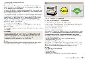 107
107 108
108 109
109 110
110 111
111 112
112 113
113 114
114 115
115 116
116 117
117 118
118 119
119 120
120 121
121 122
122 123
123 124
124 125
125 126
126 127
127 128
128 129
129 130
130 131
131 132
132 133
133 134
134 135
135 136
136 137
137 138
138 139
139 140
140 141
141 142
142 143
143 144
144 145
145 146
146 147
147 148
148 149
149 150
150 151
151 152
152 153
153 154
154 155
155 156
156 157
157 158
158 159
159