Page 221 of 364

219
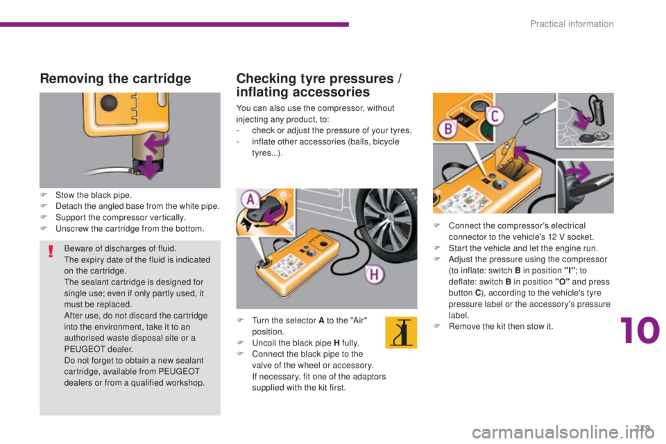
Removing the cartridge
F Stow the black pipe.
F D etach the angled base from the white pipe.
F
S
upport the compressor vertically.
F
U
nscrew the cartridge from the bottom.
Checking tyre pressures /
inflating accessories
You can also use the compressor, without
injecting any product, to:
-
c
heck or adjust the pressure of your tyres,
-
i
nflate other accessories (balls, bicycle
tyres...).
F
T
urn the selector A to the "Air"
position.
F
U
ncoil the black pipe H fully.
F
C
onnect the black pipe to the
valve of the wheel or accessory.
I
f necessary, fit one of the adaptors
supplied with the kit first. F
C
onnect the compressor's electrical
connector to the vehicle's 12 V socket.
F
S
tart the vehicle and let the engine run.
F
A
djust the pressure using the compressor
(to inflate: switch B in position "I" ; to
deflate: switch B in position "O" and press
button C ), according to the vehicle's tyre
pressure label or the accessory's pressure
label.
F
R
emove the kit then stow it.
Beware of discharges of fluid.
The expiry date of the fluid is indicated
on the cartridge.
The sealant cartridge is designed for
single use; even if only partly used, it
must be replaced.
After use, do not discard the cartridge
into the environment, take it to an
authorised waste disposal site or a
PEUGEOT dealer.
Do not forget to obtain a new sealant
cartridge, available from PEUGEOT
dealers or from a qualified workshop.
10
Practical information
Page 222 of 364

220
Temporary puncture repair kit
The kit is stowed in the boot, under the left
hand seat in the 3rd row.
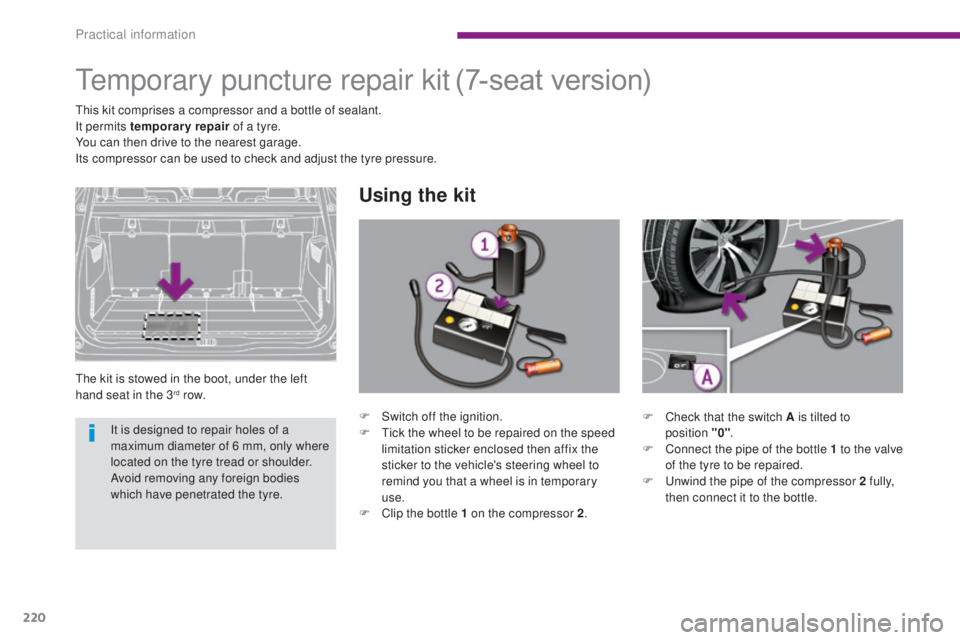
Using the kit
(7-seat version)
This kit comprises a compressor and a bottle of sealant.
It permits temporary repair of a tyre.
You can then drive to the nearest garage.
Its compressor can be used to check and adjust the tyre pressure.
F
C
heck that the switch A is tilted to
position
"0".
F
C
onnect the pipe of the bottle 1 to the valve
of the tyre to be repaired.
F
U
nwind the pipe of the compressor 2 fully,
then connect it to the bottle.
F
S
witch off the ignition.
F
T
ick the wheel to be repaired on the speed
limitation sticker enclosed then affix the
sticker to the vehicle's steering wheel to
remind you that a wheel is in temporary
use.
F
C
lip the bottle 1 on the compressor 2.
It is designed to repair holes of a
maximum diameter of 6 mm, only where
located on the tyre tread or shoulder.
Avoid removing any foreign bodies
which have penetrated the tyre.
Practical information
Page 231 of 364
229
Following a puncture
The punctured wheel cannot be stowed
under the vehicle. It must be stowed
in the boot. Use a cover to protect the
inside of the boot.
When driving with the "space-saver"
type spare wheel fitted, do not exceed
50 mph (80 km/h).
Have the tightening of the bolts and the
pressure of the spare wheel checked
by a PEUGEOT dealer or a qualified
workshop without delay.
Have the punctured wheel repaired and
replace it on the vehicle as soon as
possible.
Tyre under-inflation detection
The space-saver type or steel spare
wheel does not have a sensor.
The punctured wheel must be repaired
by a PEUGEOT dealer or a qualified
workshop.
Snow chains must only be fitted to the
front wheels. Further, they must never
be fitted to a "space-saver" spare
wheel.
Before fitting the snow chains,
interchange the "space-saver" spare
wheel fitted at the front with the wheel
at the rear on the same side.
10
Practical information
Page 233 of 364

231
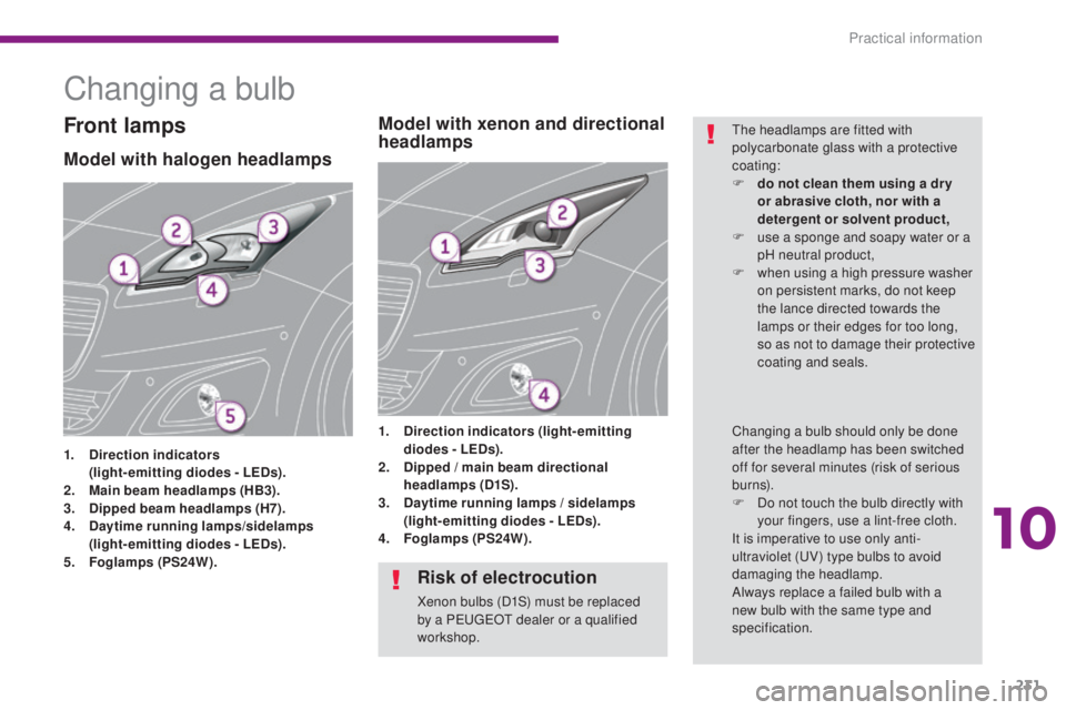
Changing a bulb
Model with halogen headlamps
1. Direction indicators (
light-emitting diodes - LEDs).
2.
M
ain beam headlamps (HB3).
3.
D
ipped beam headlamps (H7).
4.
D
aytime running lamps/sidelamps
(
light-emitting diodes - LEDs).
5.
F
oglamps (PS24W). 1.
D
irection indicators (light-emitting
diodes - LEDs).
2. D ipped / main beam directional
headlamps (D1S).
3.
D
aytime running lamps / sidelamps
(light-emitting diodes - LEDs).
4.
F
oglamps (PS24W).
Model with xenon and directional
headlampsFront lampsThe headlamps are fitted with
polycarbonate glass with a protective
coating:
F
d
o not clean them using a dr y
or abrasive cloth, nor with a
detergent or solvent product,
F
u
se a sponge and soapy water or a
pH neutral product,
F
w
hen using a high pressure washer
on persistent marks, do not keep
the lance directed towards the
lamps or their edges for too long,
so as not to damage their protective
coating and seals.
Changing a bulb should only be done
after the headlamp has been switched
off for several minutes (risk of serious
burns).
F
D
o not touch the bulb directly with
your fingers, use a lint-free cloth.
It is imperative to use only anti-
ultraviolet (UV) type bulbs to avoid
damaging the headlamp.
Always replace a failed bulb with a
new bulb with the same type and
specification.
Risk of electrocution
Xenon bulbs (D1S) must be replaced
by a PEUGEOT dealer or a qualified
workshop.
10
Practical information
Page 235 of 364
233
Changing foglamp
bulbs
Contact a PEUGEOT dealer or a qualified
workshop.
F
I
nsert a screwdriver towards the centre of
the repeater between the repeater and the
base of the mirror.
F
T
ilt the screwdriver to extract the repeater
and remove it.
F
D
isconnect the repeater connector.
Changing integrated direction
indicator side repeatersChanging dipped beam and
main beam headlamp bulbs
(models with xenon headlamps)
D1S xenon bulbs must be changed
by a PEUGEOT dealer or a qualified
workshop as there is a risk of
electrocution.
It is recommended that all D1S bulbs
are changed at the same time if one of
them fails.
You can also contact a PEUGEOT
dealer or a qualified workshop to have
these lamps changed.
To refit, carry out these operations in reverse
o r d e r.
Contact a PEUGEOT dealer or a qualified
workshop to obtain a new repeater.
10
Practical information
Page 250 of 364
248
Changing a wiper blade
Removing
F Raise the corresponding wiper arm.
F U nclip the wiper blade and remove it.
Fitting
F Put the corresponding new wiper blade in place and clip it.
F
F
old down the wiper arm carefully.
Before removing a front
wiper blade
F Within one minute after switching off the ignition, operate the wiper stalk to
position the wiper blades vertically on the
windscreen.
After fitting a front wiper
blade
F Switch on the ignition.
F O perate the wiper stalk again to park the
wiper blades.
Towing the vehicle
Access to the tools
The towing eye is installed under the left-hand
concertina board, in the boot interior trim.
For access to it:
F
o
pen the boot,
F
r
aise the concertina board,
F
r
emove the towing eye from the holder.
Procedure for having your vehicle towed or for
towing another vehicle using the removable
towing eye provided in the tool kit.
Practical information
Page 251 of 364

249
Towing your vehicle
F On the front bumper, unclip the cover by pressing at the bottom.
F
S
crew the towing eye in fully.
F
I
nstall the towing arm.
F
S
witch on the hazard warning lamps on the
towed vehicle. F
O n the rear bumper, unclip the cover by
pressing at the bottom.
F
S
crew the towing eye in fully.
F
I
nstall the towing arm.
F
S
witch on the hazard warning lamps on the
towed vehicle.
Towing another vehicle
Put the gear lever into neutral
(position N for an electronic or
automatic gearbox).
Failure to follow this instruction could
lead to damage to certain components
(brakes, transmission,
...) and the
absence of braking assistance on
restarting the engine.
General recommendations
Observe the legislation in force in your
c o unt r y.
Ensure that the weight of the towing
vehicle is higher than that of the towed
vehicle.
The driver must remain at the wheel of
the towed vehicle and must have a valid
driving licence.
When towing a vehicle with all four
wheels on the ground, always use an
approved towing arm; rope and straps
are prohibited.
The towing vehicle must move off gently.
When towing a vehicle with the engine
off, there is no longer any power
assistance for braking or steering.
In the following cases, you must always
call on a professional recovery service:
-
v
ehicle broken down on a motor way
or fast road,
-
f
our-wheel drive vehicle,
-
w
hen it is not possible to put the
gearbox into neutral, unlock the
steering, or release the parking
brake,
-
t
owing with only two wheels on the
ground,
-
w
here there is no approved towing
arm available...
10
Practical information
Page 252 of 364

250
Towbar with quickly detachable towball
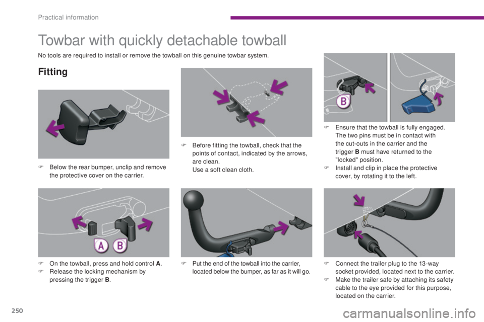
Fitting
F Below the rear bumper, unclip and remove the protective cover on the carrier. F
B
efore fitting the towball, check that the
points of contact, indicated by the arrows,
are clean. U se a soft clean cloth.F
E
nsure that the towball is fully engaged.
The two pins must be in contact with
the cut-outs in the carrier and the
trigger
B must have returned to the
"locked" position.
F I nstall and clip in place the protective
cover, by rotating it to the left.
F
O
n the towball, press and hold control A .
F
R
elease the locking mechanism by
pressing the trigger B . F
P
ut the end of the towball into the carrier,
located below the bumper, as far as it will go.
No tools are required to install or remove the towball on this genuine towbar system.
F
C
onnect the trailer plug to the 13 -way
socket provided, located next to the carrier.
F
M
ake the trailer safe by attaching its safety
cable to the eye provided for this purpose,
located on the carrier.
Practical information