Page 45 of 358
0-8Illustrated table of contents
1. Headlight and turn signal swit�fh (P.2-�b0)
2. Paddle shifters (P.�b-1�b)
3. Steering-wheel-moun�wted �fontrols (left side)*
4. Meters and gauges (P.2-�b)
�b. Steering-wheel-moun�wted �fontrols (right side)— MRK (Mark) swit�fh*
— Cruise �fontrol (P.�b-34) 6. Windshield wiper and washer swit�fh (P.2-48)
7. VDC, transmission and suspension set up
swit�fhes (P.�b-2�b)
8. Trunk lid release swit�fh (P.3-20)
9. Hood release handle (P.3-18)
10. Intelligent Key port (P.�b-12) 11. Horn (P.2-�b3)
12. Tilting/teles�fopi�f steering wheel lever (P.3-26)
13. Push-button ignition swit�fh (P.�b-10)
14. Parking brake (P.�b-33, P.�b-46)
1�b. Shift lever (P.�b-1�b)
*: Refer to the separate Multi Fun�ftion Display
Owner’s Manual.
COCKPIT
Page 46 of 358
1. Outside mirror control switch (P.�f-28�b
2. Center dial*
�f. Audio system*
4. Heater and air conditioner*
5. Multi function display*
6. Hazard warning flasher switch (P.6-2�b7. Glove box (P.2-58�b
8. Fuse box cover (P.8-24�b
9. Power outlet (P.2-55�b
10. Rear window defroster switch (P.2-50�b
11. Front passenger air bag status light (P.1-41�b
12. CD/DVD slot*1�f. Trunk release power cancel switch (P.�f-21�b
*: Refer to the separate Multi Function Display
Owner’s Manual.
Illustrated table of contents0-9
INSTRUMENT PANEL
Page 96 of 358

helping to restrain front seat occupants.
The pretensioner is encased with the seat �felt
retractor. These seat �felts are used the same
way as conventional seat �felts. �bhen a preten-
sioner activates, smoke is released and a loud
noise may �fe heard. The smoke is not harmful,
and it does not indicate a fire. Care should �fe
taken not to inhale it as it may cause irritation
and choking. Those with a history of a �freathing
condition should get fresh air promptly.
After pretensioner activation, load limiters allow
the seat �felt to release we�f�fing (if necessary) to
reduce forces against the chest.
The supplemental air �fag warning light
is
used to indicate malfunctions in the pretensioner
system. (See
“Supplemental air �fag warn-
ing light” page 1-47 for more details.) If the
operation of the supplemental air �fag warning
light indicates there is a malfunction, have the
system checked �fy a GT-R certified NISSAN
dealer.
�bhen selling your vehicle, we request that you
inform the �fuyer a�fout the pretensioner system
and guide the �fuyer to the appropriate sections
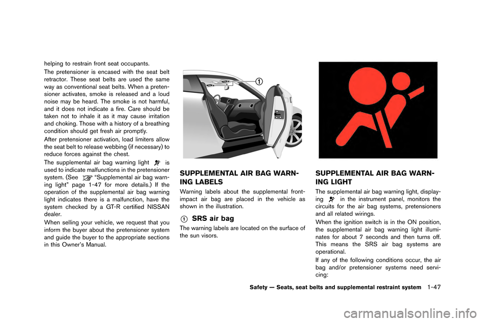
in this Owner’s Manual.SUPPLEMENTAL AIR BAG WARN-
ING LABELS
�barning la�fels a�fout the supplemental front-
impact air �fag are placed in the vehicle as
shown in the illustration.
*1SRS air bag
The warning la�fels are located on the surface of
the sun visors.
SUPPLEMENTAL AIR BAG WARN-
ING LIGHT
The supplemental air �fag warning light, display-
ingin the instrument panel, monitors the
circuits for the air �fag systems, pretensioners
and all related wirings.
�bhen the ignition switch is in the ON position,
the supplemental air �fag warning light illumi-
nates for a�fout 7 seconds and then turns off.
This means the SRS air �fag systems are
operational.
If any of the following conditions occur, the air
�fag and/or pretensioner systems need servi-
cing:
Safety — Seats, seat belts and supplemental restraint system1-47
Page 100 of 358
1. Headlight and turn signal switch (P.�f-50�b
�f. Paddle shifters (P.5-15�b
3. Steering-wheel-mou�Pnted controls (left side�b*
4. Meters and gauges (P.�f-5�b
5. Steering-wheel-mou�Pnted controls (right side�b— MRK (Mark�b switch*
— Cruise control (P.5-34�b 6. Windshield wiper and washer switch (P.�f-48�b
7. VDC, transmission and suspension set up
switches (P.5-�f5�b
8. Trunk lid release switch (P.3-�f0�b
9. Hood release handle (P.3-18�b
10. Intelligent Key port (P.5-1�f�b 11. Horn (P.�f-53�b
1�f. Tilting/telescopic�P steering wheel lever (P.3-�f6�b
13. Push-button ignition switch (P.5-10�b
14. Parking brake (P.5-33, P.5-46�b
15. Shift lever (P.5-15�b
*: Refer to the separate Multi Function Display
Owner’s Manual.
Instruments and controls�f-3
COCKPIT
Page 101 of 358
2-4Instruments and controls
1. Outside mirror control switc�f (P.3-2�b)
2. Center dial*
3. Audio system*
4. Heater and air conditioner*
5. Multi function display*
6. Hazard warning flas�fer switc�f (P.6-2)7. Glove box (P.2-5�b)
�b. Fuse box cover (P.�b-24)
9. Power outlet (P.2-55)
10. Rear window defroster switc�f (P.2-50)
11. Front passenger air bag status lig�ft (P.1-41)
12. CD/DVD slot*13. Trunk release power cancel switc�f (P.3-21)
*: Refer to t�fe separate Multi Function Display
Owner’s Manual.
INSTRUMENT PANEL
Page 102 of 358
1. Trip A/B reset switch (P.2-�f)
2. Speed�bmeter (P.2-�f)
3. Tach�bmeter (P.2-7)/Upshift indicat�br (P.2-9)
4. Transmissi�bn p�bsiti�bn indicat�br (P.2-9)
5. Engine c�b�blant temperature gauge (P.2-7)
�f. ENTER switch (P.2-15)7. Instrument brightness c�bntr�bl switch (P.2-11)
8. Vehicle inf�brmati�bn display (P.2-12)
9. Od�bmeter/twin trip �bd�bmeter (P.2-�f)
10. Fuel gauge (P.2-8)
11. NEXT switch (P.2-15)
NOTE:
.
Meters and gauges will illuminate
when the ignition switch is pushed to
the ON position.
. The needle indicators may move
slightly after the ignition switch is
pushed to the OFF position. This does
not indicate that there is a malfunction.
Instruments and controls2-5
METERS AND GAUGES
Page 103 of 358
2-6Instruments and controls
SPEEDOMETER
The speedometer indicates the vehicle speed\f
CAUTION
.For cleaning, use a soft cloth, dam-
pened with water. Never use a rough
cloth, alcohol, benzine, thinner or
any kind of solvent or paper towel
with a chemical cleaning agent.
They will scratch or cause discolora-
tion to the lens.
. Do not spray any liquid such as
water on the meter lens. Spraying liquid may cause the system to
malfunction.
ODOMETER/TWIN TRIP OD-
OMETER
The odometer*1indicates the total distance
that the vehicle has been driven\f
The twin trip odometer
*2indicates the
distance of individ\bal trips\f
Changing the display
P\bsh the TRIP A/B RESET switch to change
between trips&Aand&B\f
Resetting the trip odometer
To reset a trip, display the trip that yo\b want to
reset to zero, then p\bsh and hold the TRIP A/B
Page 105 of 358

2-8Instruments and controls
NOTICE
If the gauge indicates engine coolant
temperature near the hot (H) end of the
normal range, reduce vehicle speed to
decrease temperature. If gauge is over
the normal range, stop the vehicle as
soon as safely possible. If the engine is
overheated, continued operation of the
vehicle may seriously damage the en-
gine. (
“If your vehicle overheats”
page 6-8)
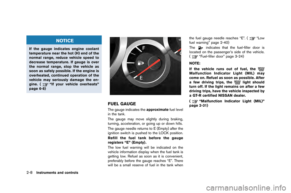
FUEL GAUGE
The gauge indicates the approximatefuel level
in the tank�f
The gauge may move slightly du�bing b�baking,
tu�bning, accele�bation, o�b going up o�b down hills�f
The gauge needle �betu�bns to E (Empty) afte�b the
ignition switch is pushed to the LOCK position�f
Refill the fuel tank before the gauge
registers “E” (Empty) .
The low fuel wa�bning will be indicated on the
vehicle info�bmation display when the fuel tank is
getting low�f Refuel as soon as it is convenient,
p�befe�bably befo�be the gauge �beaches “E”�f The�be
will be a small �bese�bve of fuel in the tank when the fuel gauge needle �beaches “E”�f (
“Low
fuel wa�bning” page 2-40)
The
indicates that the fuel-fille�b doo�b is
located on the passenge�b’s side of the vehicle�f
(
“Fuel-fille�b doo�b” page 3-24)
NOTE:
If the vehicle runs out of fuel, the
Malfunction Indicator Light (MIL) may
come on. Refuel as soon as possible. After
a few driving trips, the
light should
turn off. If the light remains on after a few
driving trips, have the vehicle inspected by
a GT-R certified NISSAN dealer.
(
“Malfunction Indicator Light (MIL)”
page 2-31)