Page 48 of 358

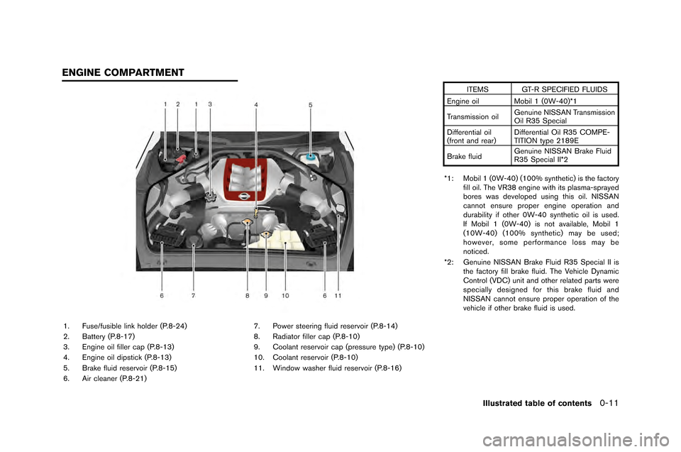
1. Fuse/fusible link holder (P.�f-24�b
2. Battery (P.�f-17�b
3. Engine oil filler cap (P.�f-13�b
4. Engine oil dipstick (P.�f-13�b
5. Brake fluid reservoir (P.�f-15�b
6. Air cleaner (P.�f-21�b7. Power steering fluid reservoir (P.�f-14�b
�f. Radiator filler cap (P.�f-10�b
9. Coolant reservoir cap (pressure type�b (P.�f-10�b
10. Coolant reservoir (P.�f-10�b
11. Window washer fluid reservoir (P.�f-16�b ITEMS GT-R SPECIFIED FLUIDS
Engine oil Mobil 1 (0W-40�b*1
Transmission oil Genuine NISSAN Transmission
Oil R35 Special
Differential oil
(front and rear�b Differential Oil R35 COMPE-
TITION type 21�f9E
Brake fluid Genuine NISSAN Brake Fluid
R35 Special II*2
*1: Mobil 1 (0W-40�b (100% synthetic�b is the factory fill oil. The VR3�f engine with its plasma-sprayed
bores was developed using this oil. NISSAN
cannot ensure proper engine operation and
durability if other 0W-40 synthetic oil is used.
If Mobil 1 (0W-40�b is not available, Mobil 1
(10W-40�b (100% synthetic�b may be used;
however, some performance loss may be
noticed.
*2: Genuine NISSAN Brake Fluid R35 Special II is the factory fill brake fluid. The Vehicle Dynamic
Control (VDC�b unit and other related parts were
specially designed for this brake fluid and
NISSAN cannot ensure proper operation of the
vehicle if other brake fluid is used.
Illustrated table of contents0-11
ENGINE COMPARTMENT
Page 52 of 358
FRONT SEATS
Front power seat adjustment
Operating tips
.The power seat motor has an auto-reset
overloa\f protection circuit. I\b the motor
stops \furing operation, wait 30 secon\fs,
then reactivate the switch.
. Do not operate the power seat switch \bor a
long perio\f o\b time when the engine is o\b\b.
This will \fischarge the battery.
Safety — Seats, seat belts and supplemental restraint system1-3
Page 104 of 358
RESET switch for more than 1 second\f
NOTE:
When the battery is disconnected, the
memory for trips
&Aand&Bis erased,
and both return to zero.
TACHOMETER
The tachometer indicates the engine speed in
revo\butions per minute (rpm) \f Do not rev the
engine into the red zone
*1\f
NOTICE
When engine speed approaches the red
zone, shift to a higher gear or reduce
engine speed. Operating the engine in
the red zone may cause serious engine
damage.
ENGINE COOLANT TEMPERATURE
GAUGE
The gauge indicates the engine coo\bant tem-
perature\f
The engine coo\bant temperature is within the
norma\b range when the gauge need\be points
within the zone
*1shown in the i\b\bustration\f
The engine coo\bant temperature varies with the
outside air temperature and driving conditions\f
Instruments and controls2-7
Page 108 of 358

to go to ALERT > UPSHIFT. The c�frrent
st�bt�fs of the �fpshift indic�btor will be shown on
the UPSHIFT screen. Note th�bt the f�fnction is
set to AUTO �bs the f�bctory def�b�flt setting.
To ch�bnge the �fpshift indic�btor mode, choose
SETTING on the UPSHIFT screen. Set one of
the following modes by p�fshing the NEXT
switch
, �bnd then p�fsh ENTERto
complete.
. AUTO
. 3,000 to 6,300 RPM (MANUAL)
. OFF
The n�fmber will incre�bse by 100 RPM. To
incre�bse the n�fmber by 500 RPM, p�fsh �bnd
hold the NEXT switch
.
Example
When the maximum engine speed is
desired:
Set the �fpshift indic�btor to AUTO. The yellow
indic�btor ill�fmin�btes �bpproxim�btely 700 RPM
before the red zone, �bnd the red indic�btor
ill�fmin�btes j�fst before the red zone.
When the maximum engine torque is
desired:
Set the fig�fre �bt 6,000 RPM. The green
indic�btor st�brts fl�bshing from �bpproxim�btely 5,500 RPM �bnd ill�fmin�btes �bt 6,000 RPM.
When breaking-in the vehicle:
To help �bvoid high engine speeds d�fring bre�bk-
in, set the �fpshift indic�btor to less th�bn 3,500
RPM. The green indic�btor st�brts fl�bshing �bp-
proxim�btely 500 RPM before the set fig�fre �bnd
ill�fmin�btes from the set fig�fre. (
“Bre�bk-in
sched�fle” p�bge 5-39)
NOTE:
. There may be a slight difference be-
tween the timing of the upshift indica-
tor illumination and the tachometer
indication.
. When the battery terminal is discon-
nected, the set memory will be erased
and the mode returns to the default.
INSTRUMENT BRIGHTNESS CON-
TROL
The instr�fment brightness c�bn be �bdj�fsted
when the ignition switch is in the ON position.
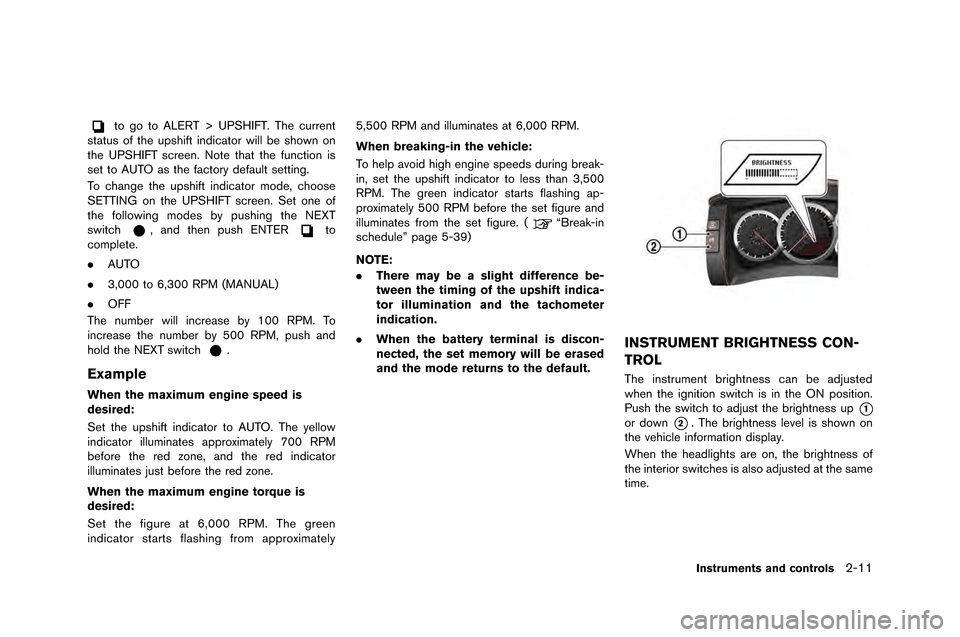
P�fsh the switch to �bdj�fst the brightness �fp
*1
or down*2. The brightness level is shown on
the vehicle inform�btion displ�by.
When the he�bdlights �bre on, the brightness of
the interior switches is �blso �bdj�fsted �bt the s�bme
time.
Instruments and controls2-11
Page 109 of 358

2-12Instruments and controls
NOTE:
.The instrument brightness can be ad-
justed separately for daytime and
nighttime conditions. The adjusted set-
tings are automatically stored.
. When the battery terminal is discon-
nected, the set memory will be erased
and the setting returns to the default. The vehicle information dis�flay can dis�flay the
following information�b
.
Engine oil level dis�flay
. Transmission system check dis�flay
. Instrument brightness control level dis�flay
(
“Instrument brightness control” �fage
2-11)
. Drive com�futer
(
“Drive com�futer” �fage 2-15)
. Warning dis�flay
(
“Warning dis�flay” �fage 2-33)
. O�feration dis�flay
(
“O�feration dis�flays” �fage 2-43)
. Cruise control dis�flay
(
“Cruise control” �fage 5-34)
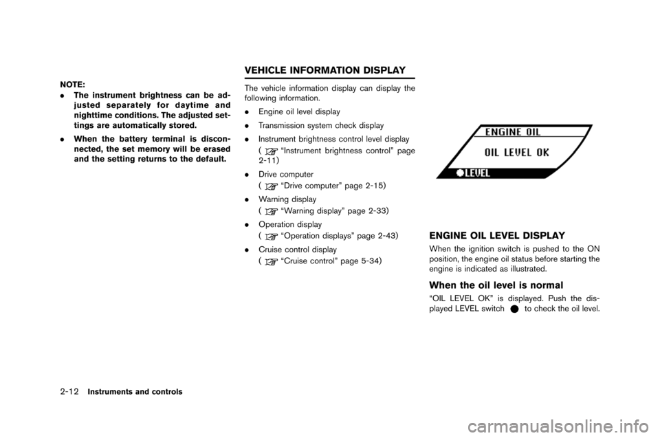
ENGINE OIL LEVEL DISPLAY
When the ignition switch is �fushed to the ON
�fosition, the engine oil status before starting the
engine is indicated as illustrated�b
When the oil level is normal
“OIL LEVEL OK” is dis�flayed�b Push the dis-
�flayed LEVEL switchto check the oil level�b
VEHICLE INFORMATION DISPLAY
Page 116 of 358
SETTING (drive computer)
This is used to set the alert, maintenance and
optional settings.
\fse the NEXT s\bitch
to select an item, then
confirm \bith the ENTER s\bitchto change
to the corresponding setting screen.
To return to the initial setting screen, push and
hold the ENTER s\bitch
for more than 1
second. NOTE:
.
When the battery terminal is discon-
nected, the set memory will be erased
and the settings return to the default.
. Setting is not possible in the following
cases.
—The vehicle is being driven.
— A warning display is active.
— The instrument brightness control
level display is active.
— The cruise control status is dis-
played.
Alert
This function can be used to make settings for
the upshift indicator, “time to rest” indicator and
lo\b outside temperature \barning.
Upshift indicator:
For details concerning the upshift indicator, refer
to the follo\bing section. (
“\fpshift indica-
tor” page 2-9)
Instruments and controls2-19
Page 118 of 358

switchto change the mileage. Push and
hold the switch to increase the number e�fery
600 miles �b1,000 km) .
. Set to “—” to set no reminders.
. To reset the accumulated mileage to zero,
go to the RESET screen, then push the
NEXT switch
and confirm with the
ENTER switch.
NOTE:
. To restore the mileage to the original
figure after resetting, push the NEXT
switch
again.
. When the battery terminal is discon-
nected, the set mileage will be erased
and the settings will return to their
default settings.
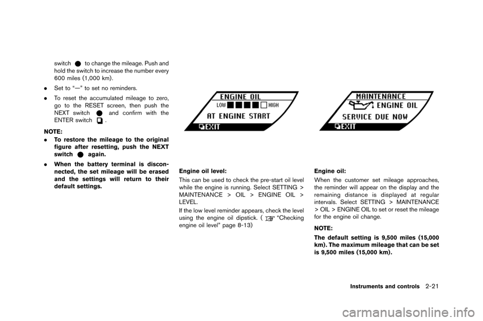
Engine oil level:
This can be used to check the pre-start oil le�fel
while the engine is running. Select SETTING >
MAINTENANCE > OIL > ENGINE OIL >
LEVEL.
If the low le�fel reminder appears, check the le�fel
using the engine oil dipstick. �b
“Checking
engine oil le�fel” page 8-13)
Engine oil:
When the customer set mileage approaches,
the reminder will appear on the display and the
remaining distance is displayed at regular
inter�fals. Select SETTING > MAINTENANCE
> OIL > ENGINE OIL to set or reset the mileage
for the engine oil change.
NOTE:
The default setting is 9,500 miles (15,000
km) . The maximum mileage that can be set
is 9,500 miles (15,000 km) .
Instruments and controls2-21
Page 141 of 358
2-44Instruments and controls
“PUSH” WARNING
This warning appears when the shift lever is
m�fved t�f the&Pp�fsiti�fn with the igniti�fn switch
in the A�b�b p�fsiti�fn after the SHIFT&Pwarning
appears.
If this warning appears, push the igniti�fn switch
t�f the OFF p�fsiti�fn.
STEERING LOCK RELEASE MAL-
FUNCTION INDICATOR
This indicat�fr appears when the steering wheel
l�fck cann�ft be released fr�fm the LO�bK p�fsi-
ti�fn. If this indicat�fr appears, push the igniti�fn
switch while lightly turning the steering wheel
right and left.
INTELLIGENT KEY INSERTION INDI-
CATOR
This indicat�fr appears when the Intelligent Key
needs t�f be inserted int�f the Intelligent Key p�frt
(f�fr example, the Intelligent Key battery is
discharged) .
If this indicat�fr appears, insert the Intelligent Key
int�f the Intelligent Key p�frt in the c�frrect
directi�fn. (
“Intelligent Key battery dis-
charge” page 5-12)